After finishing maintenance, I will restart this process.
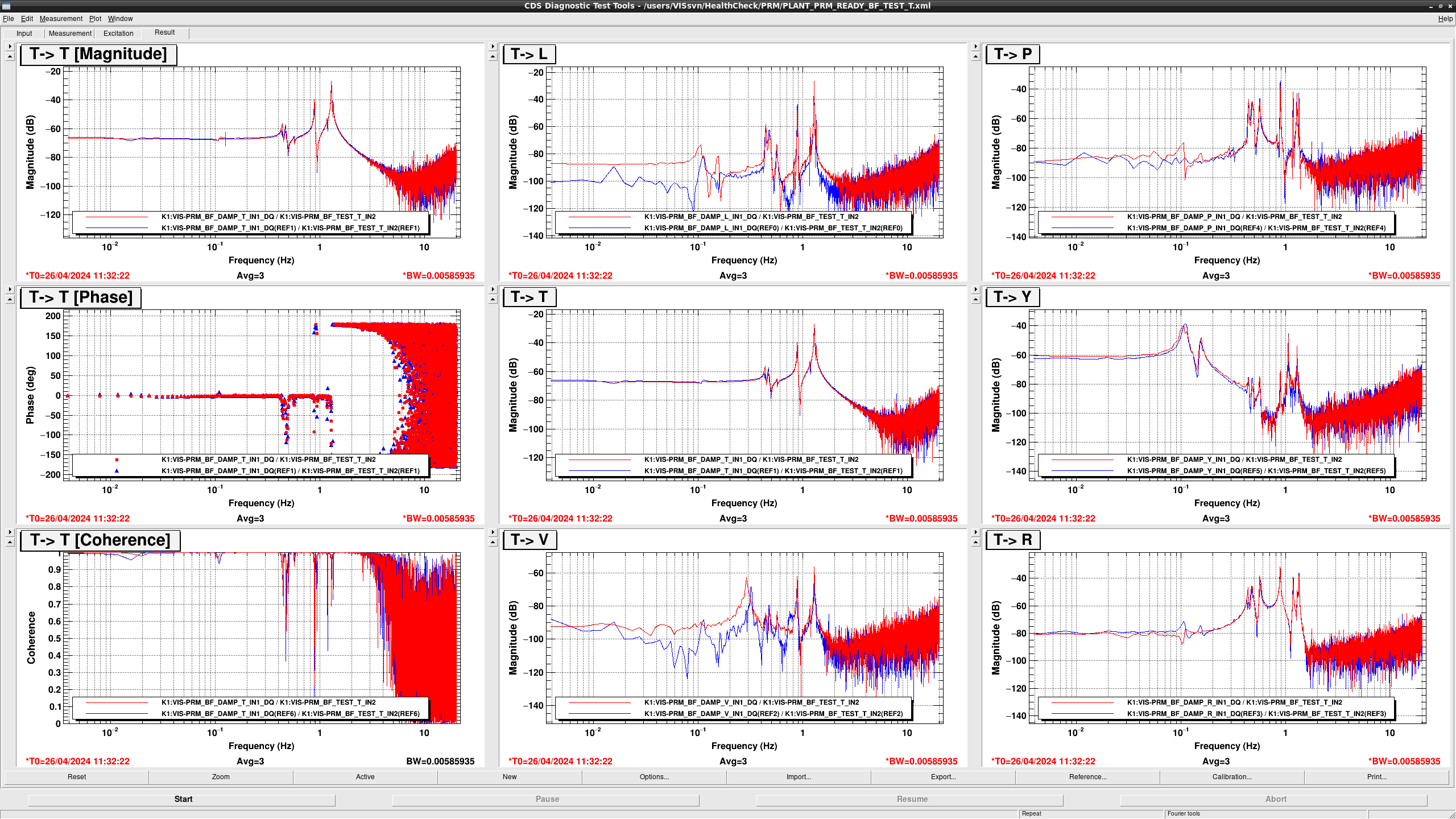
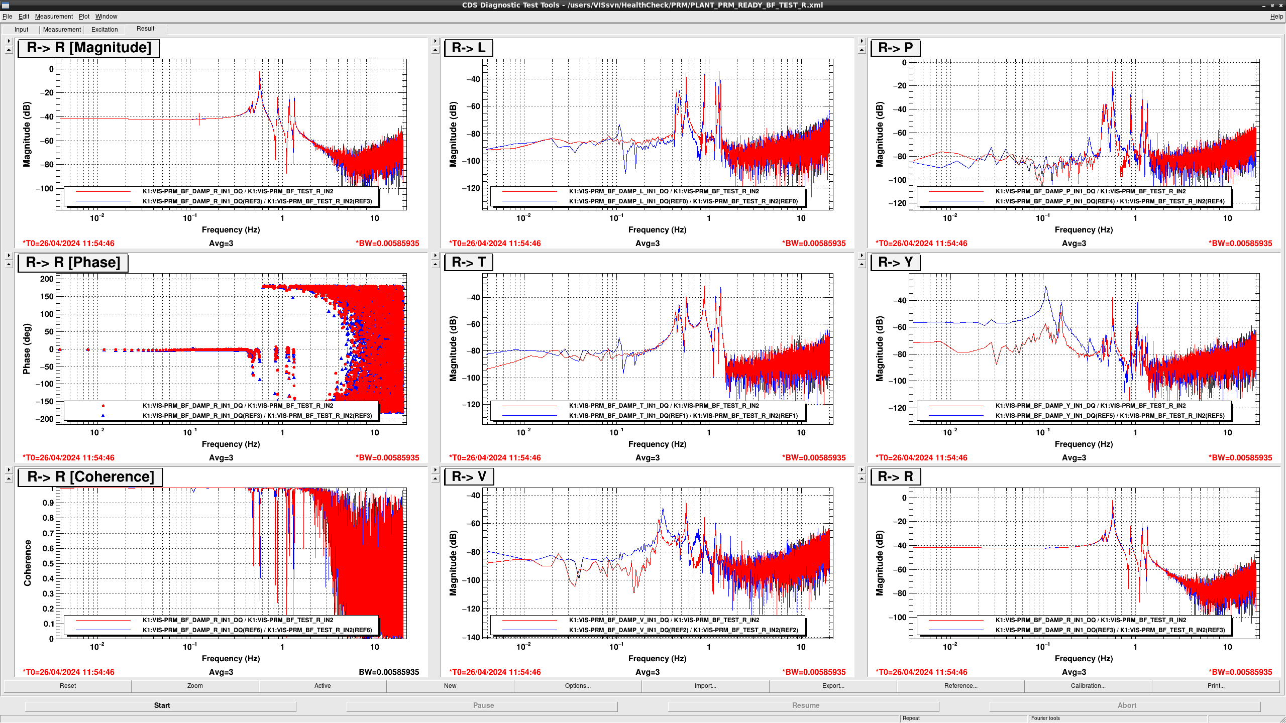
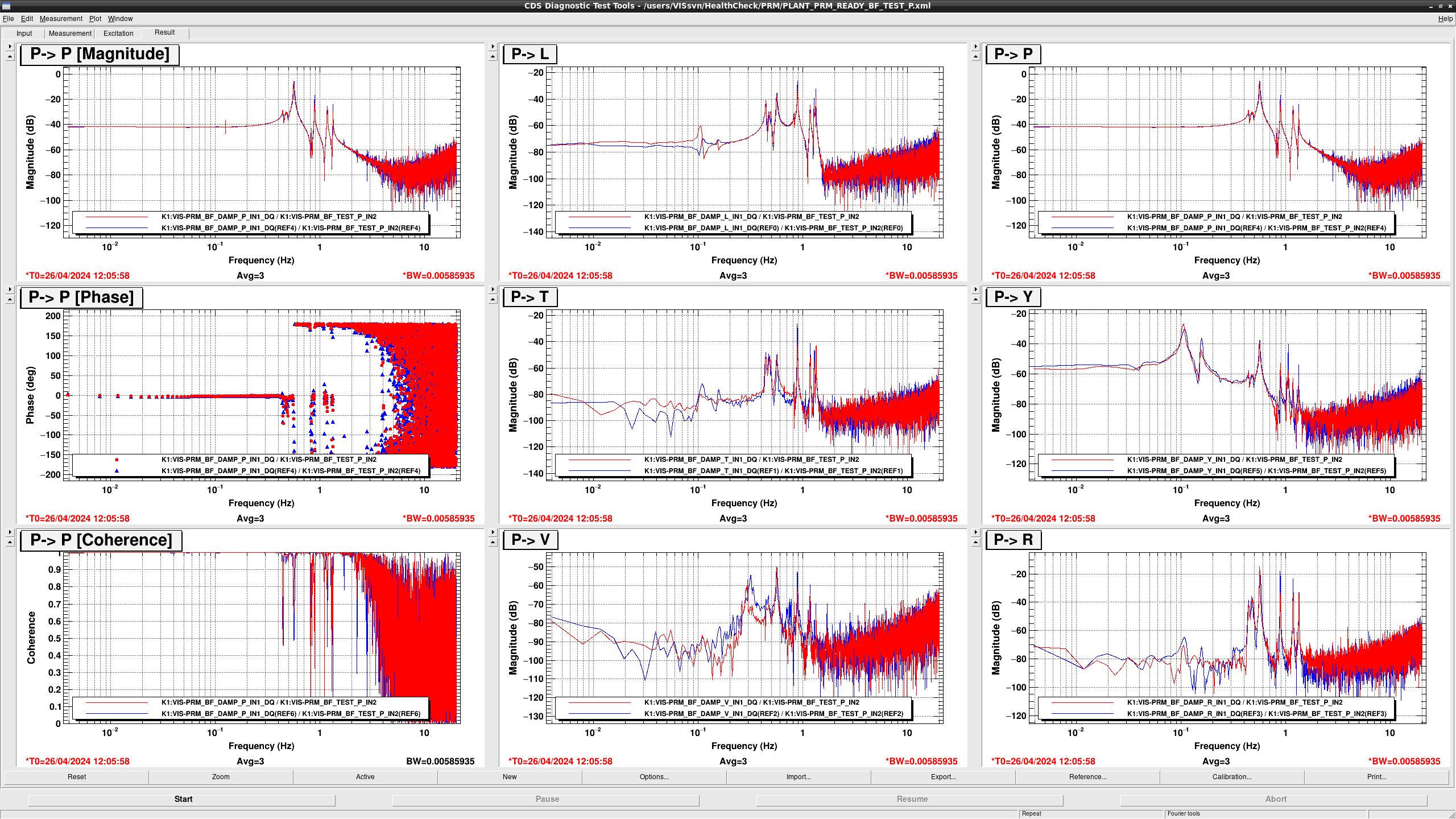
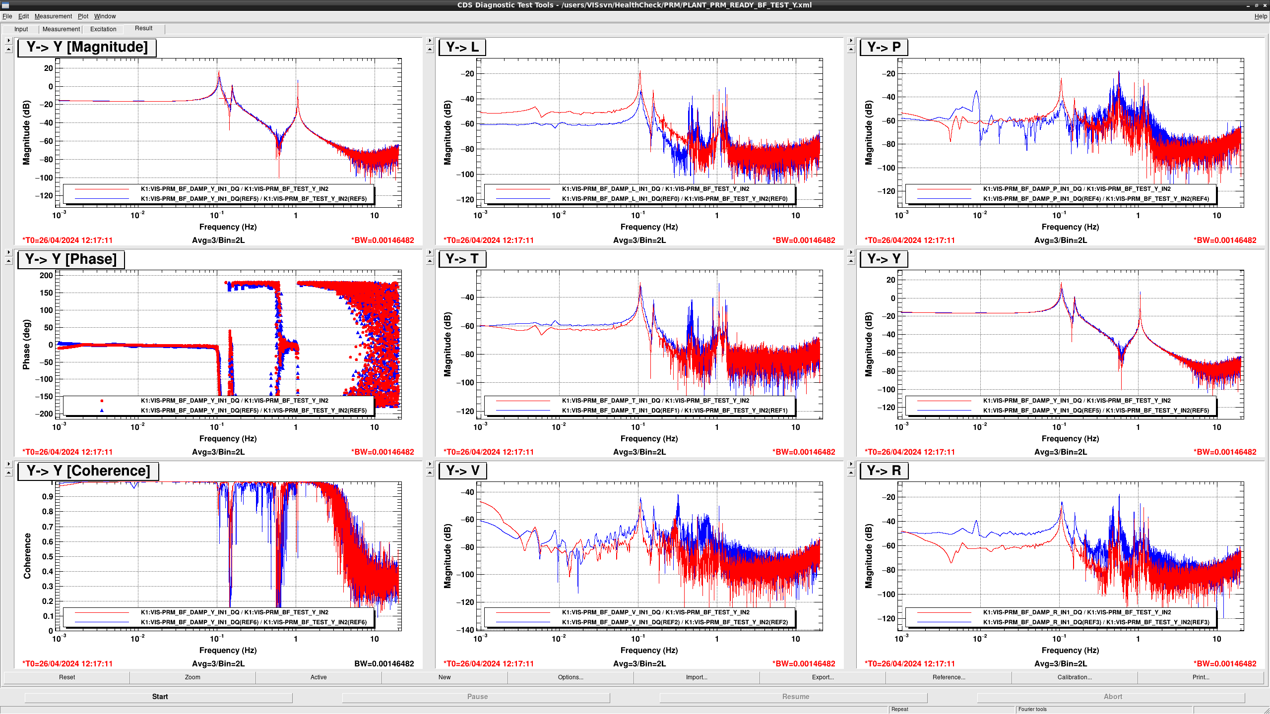
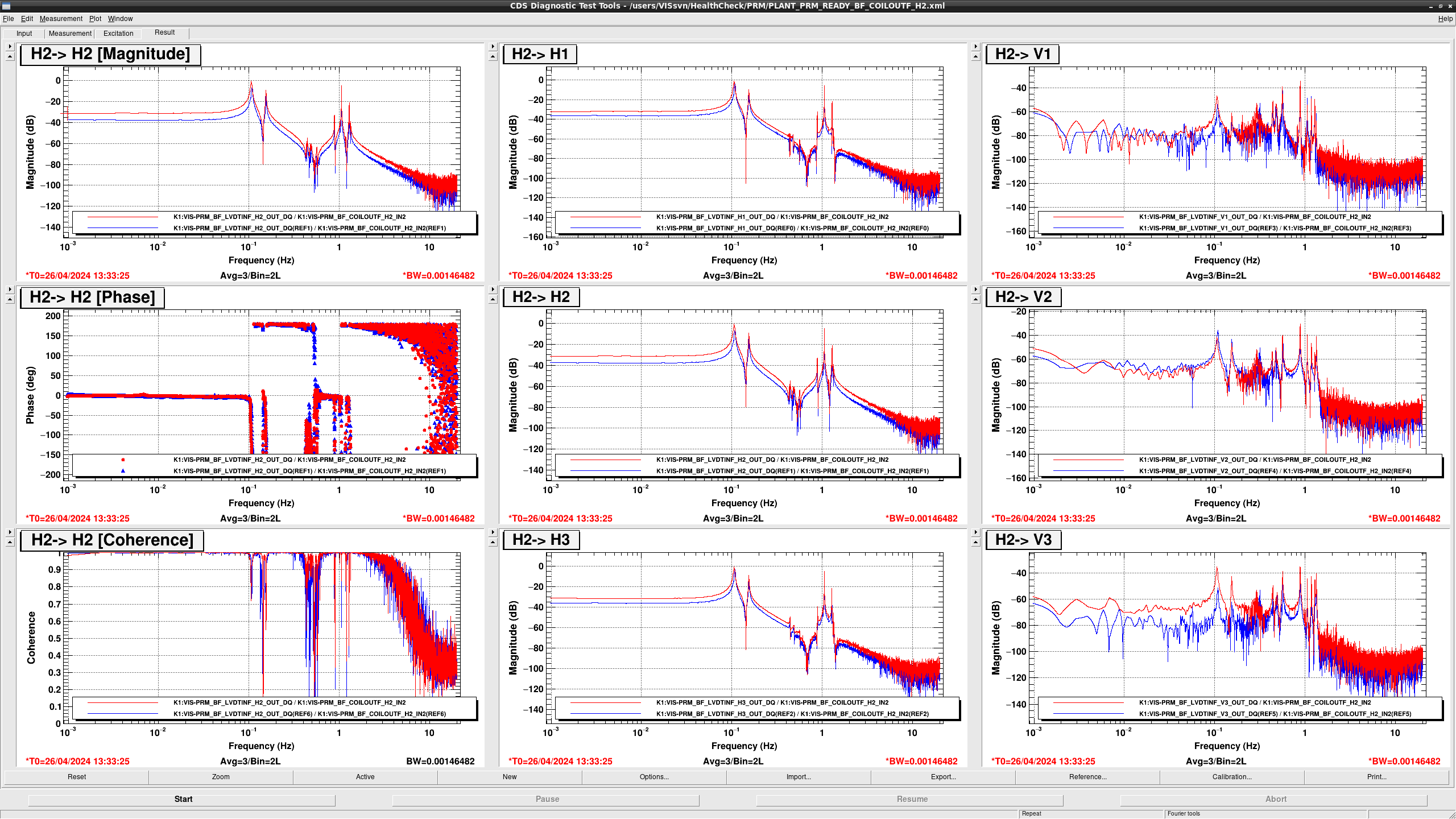
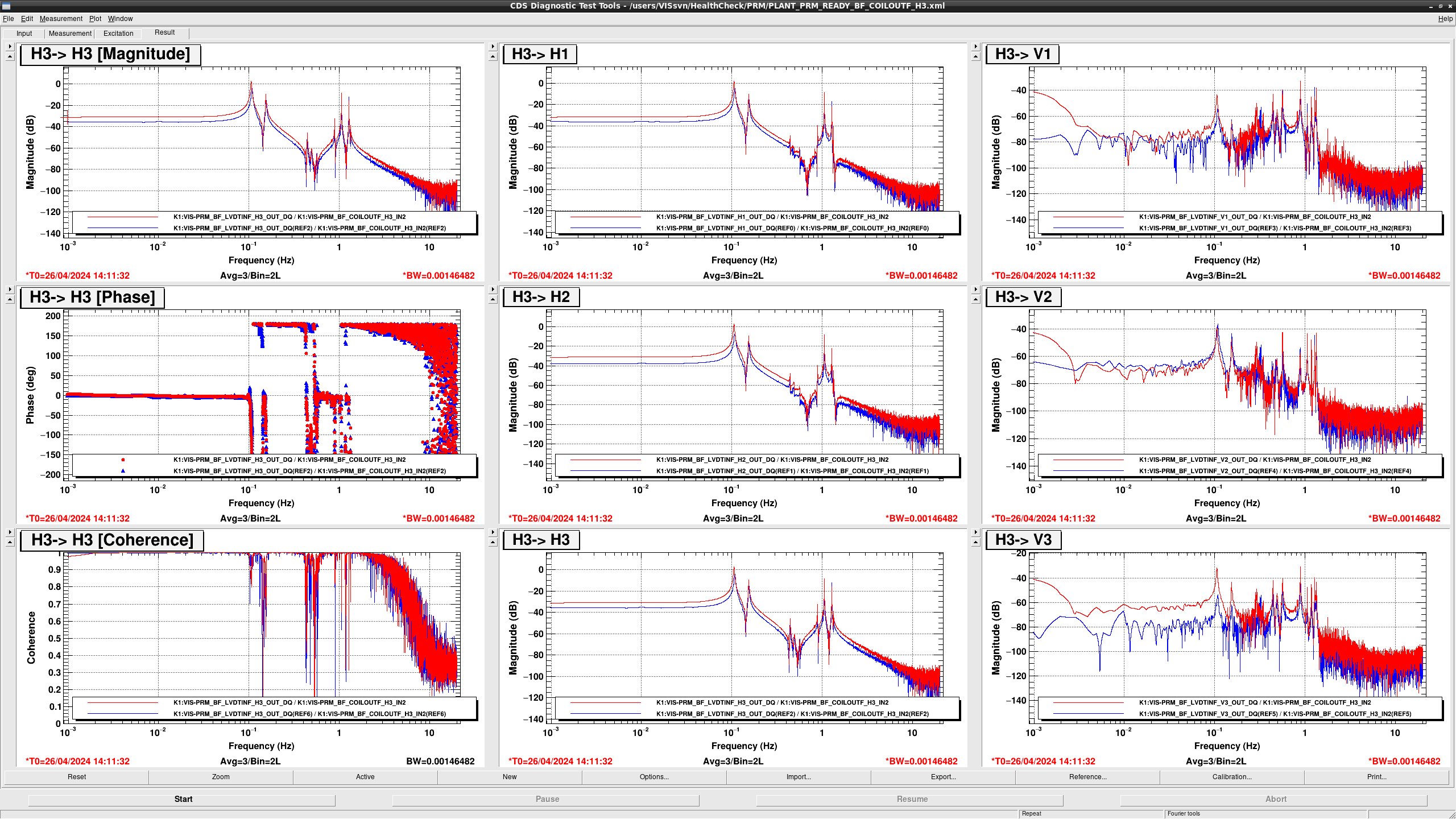
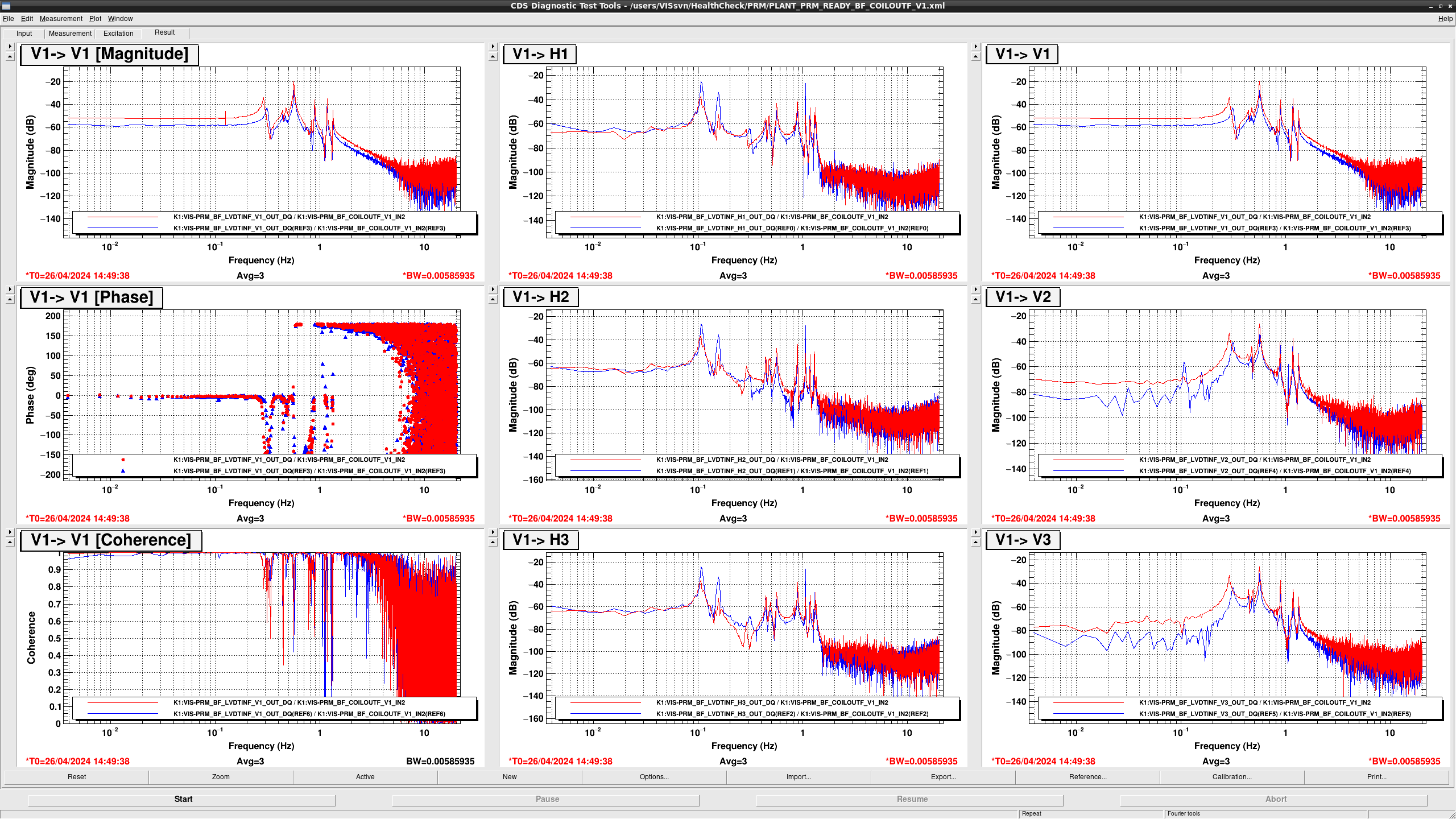
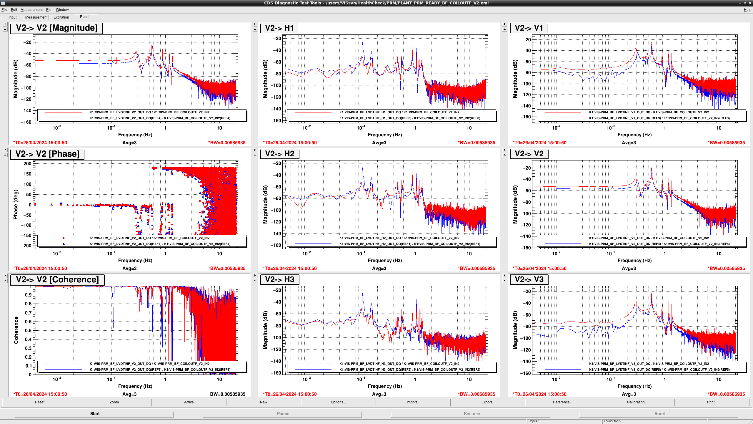
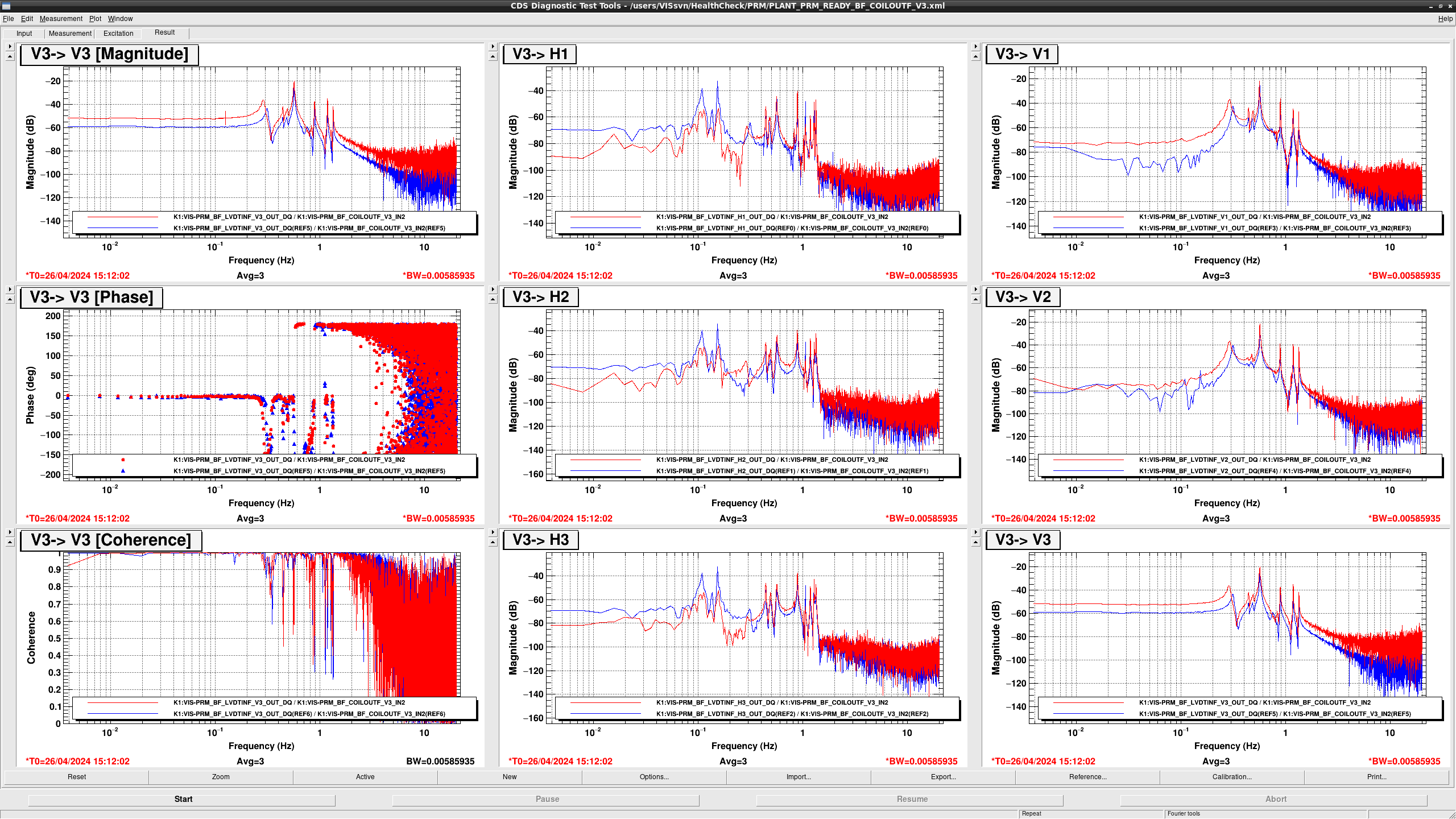
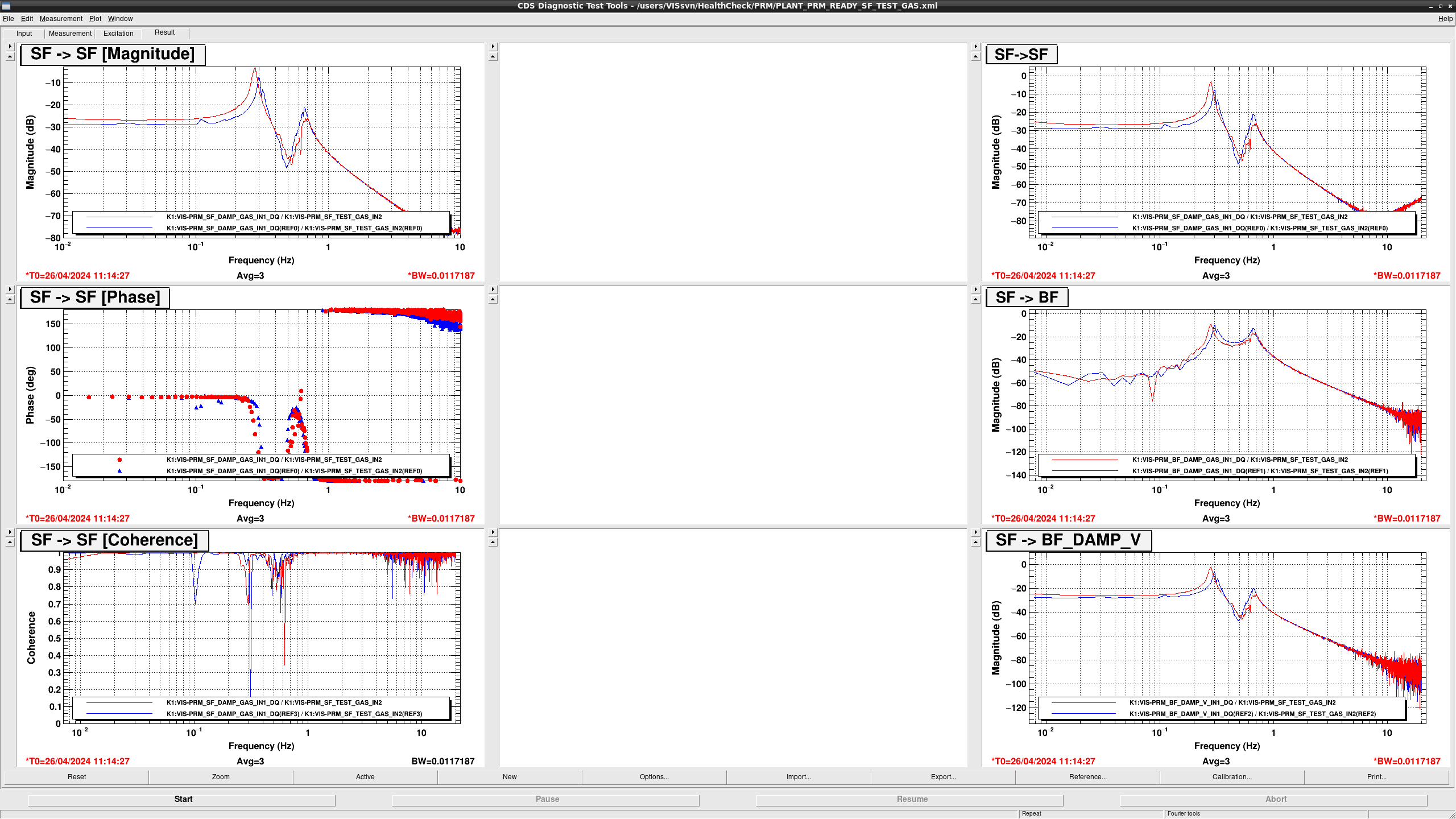
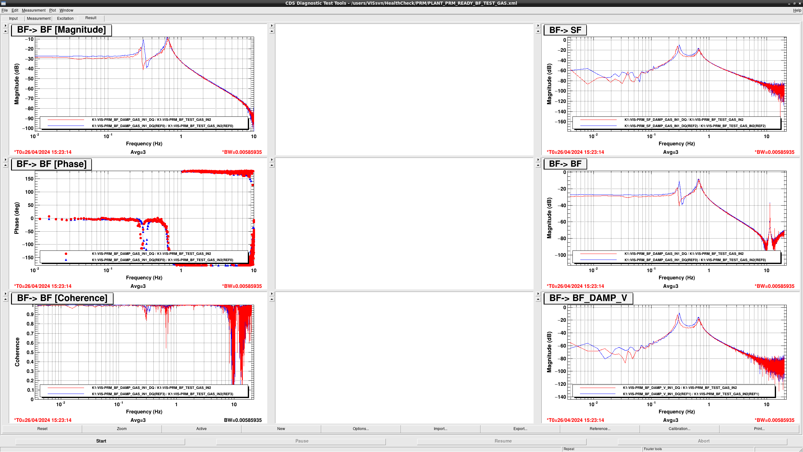
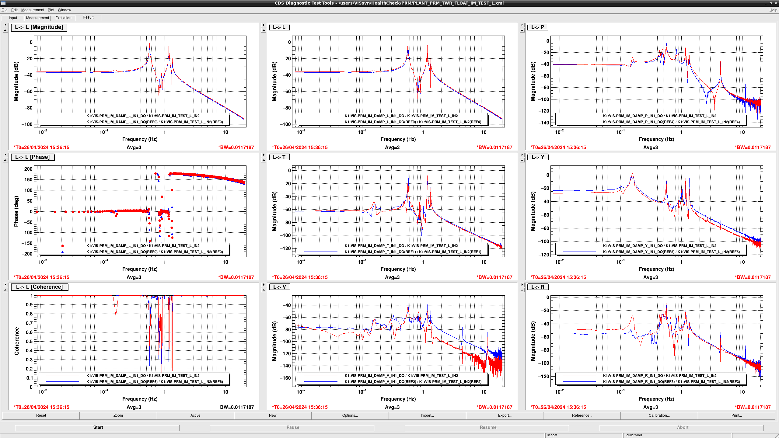
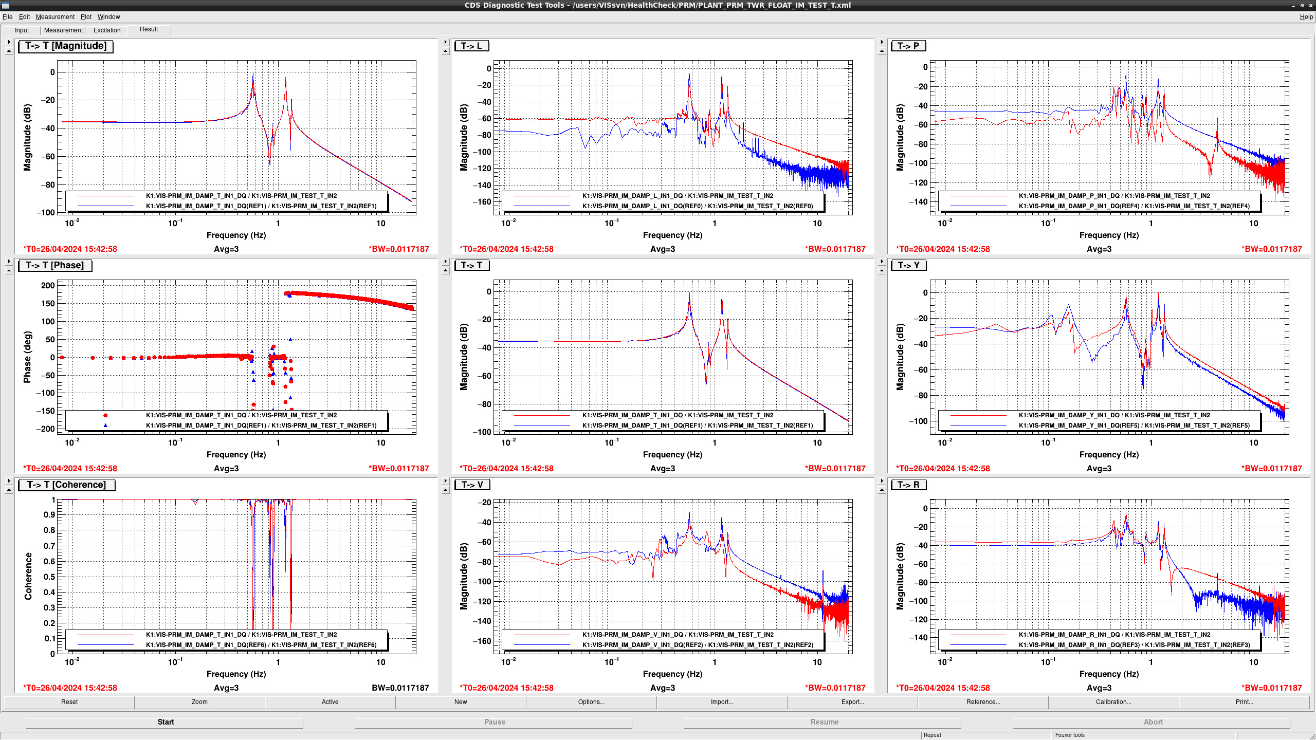
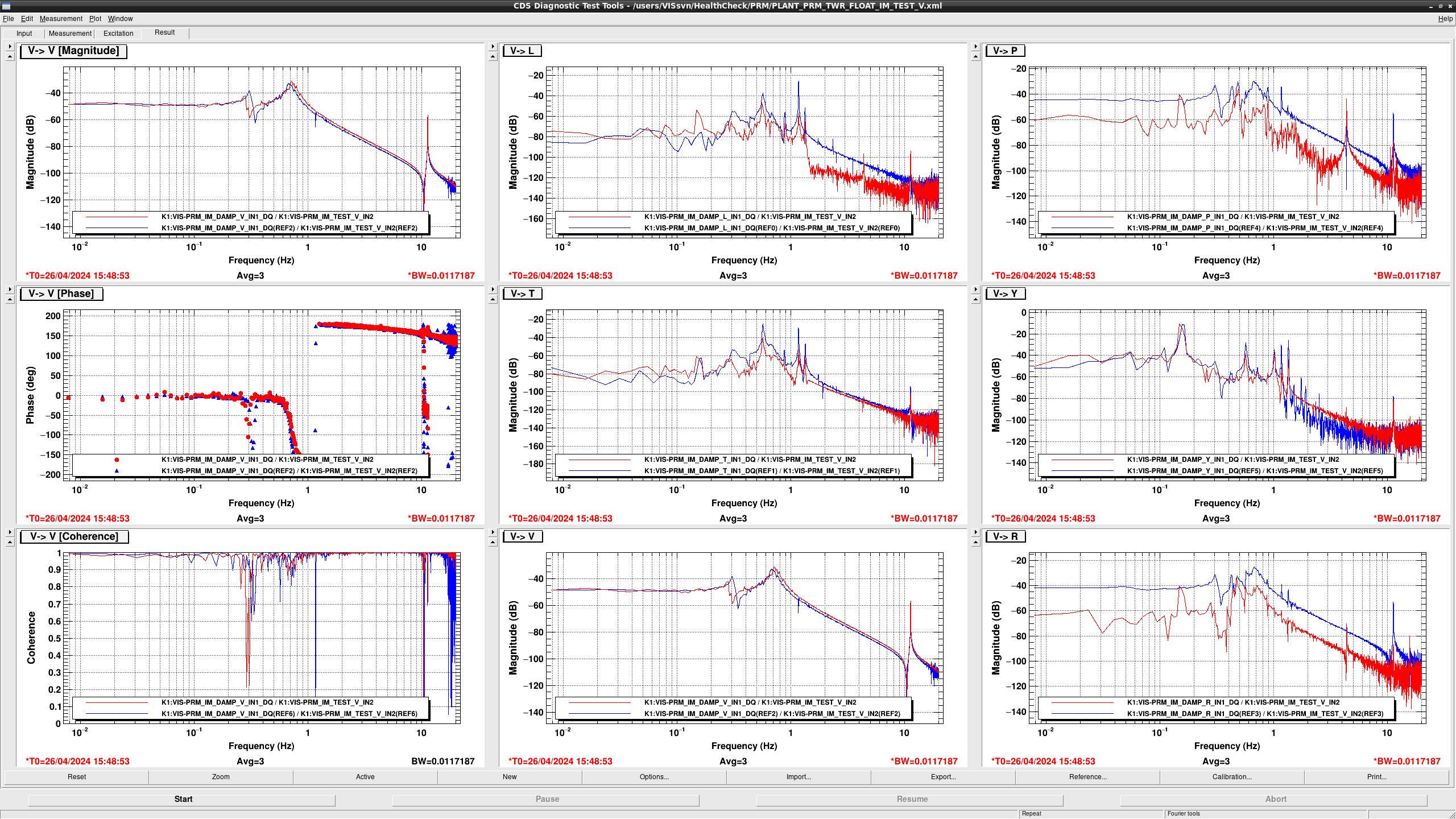
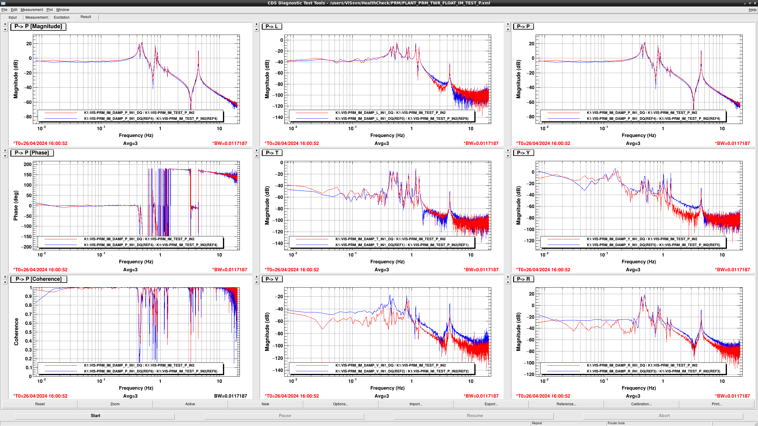
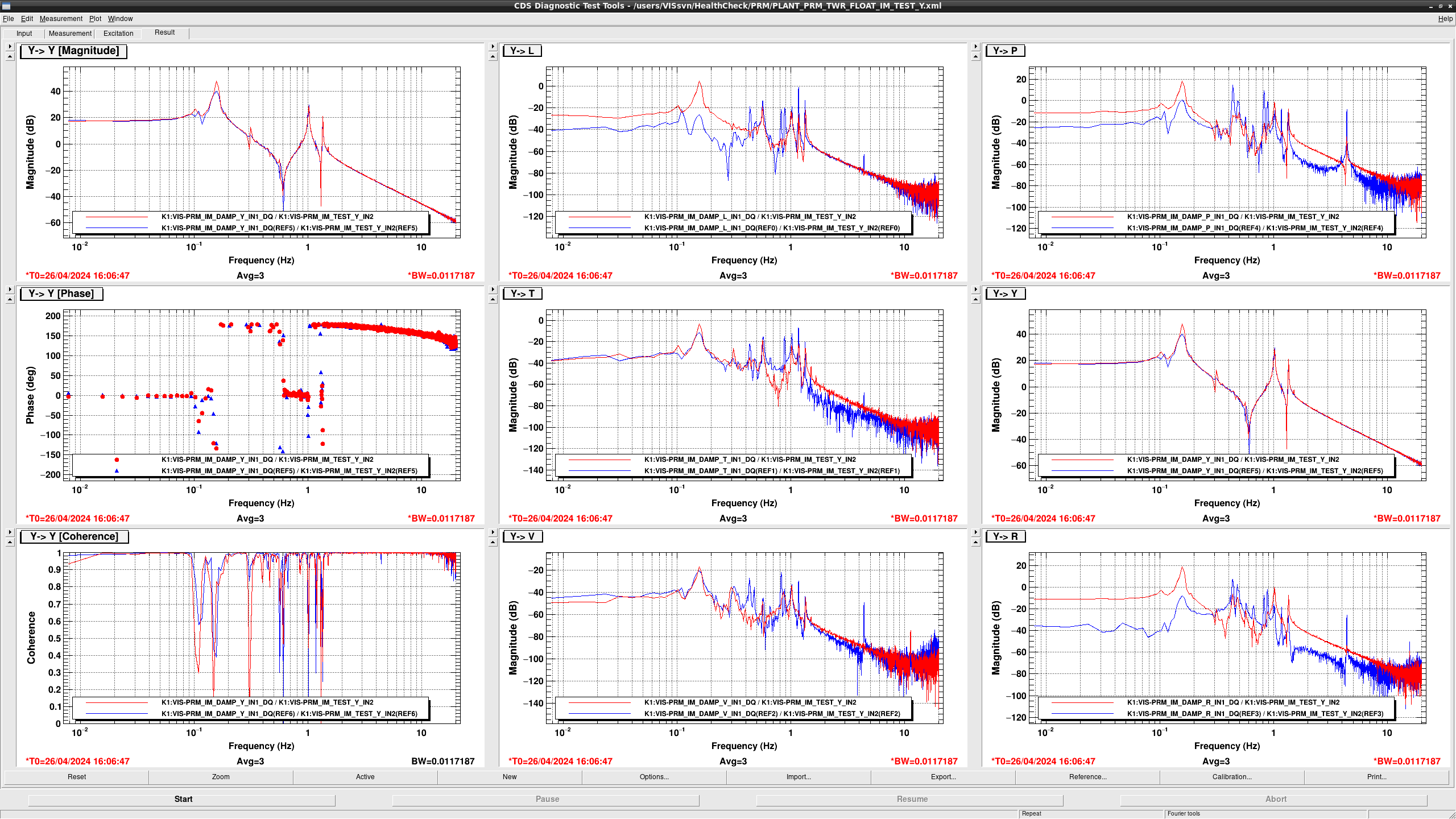
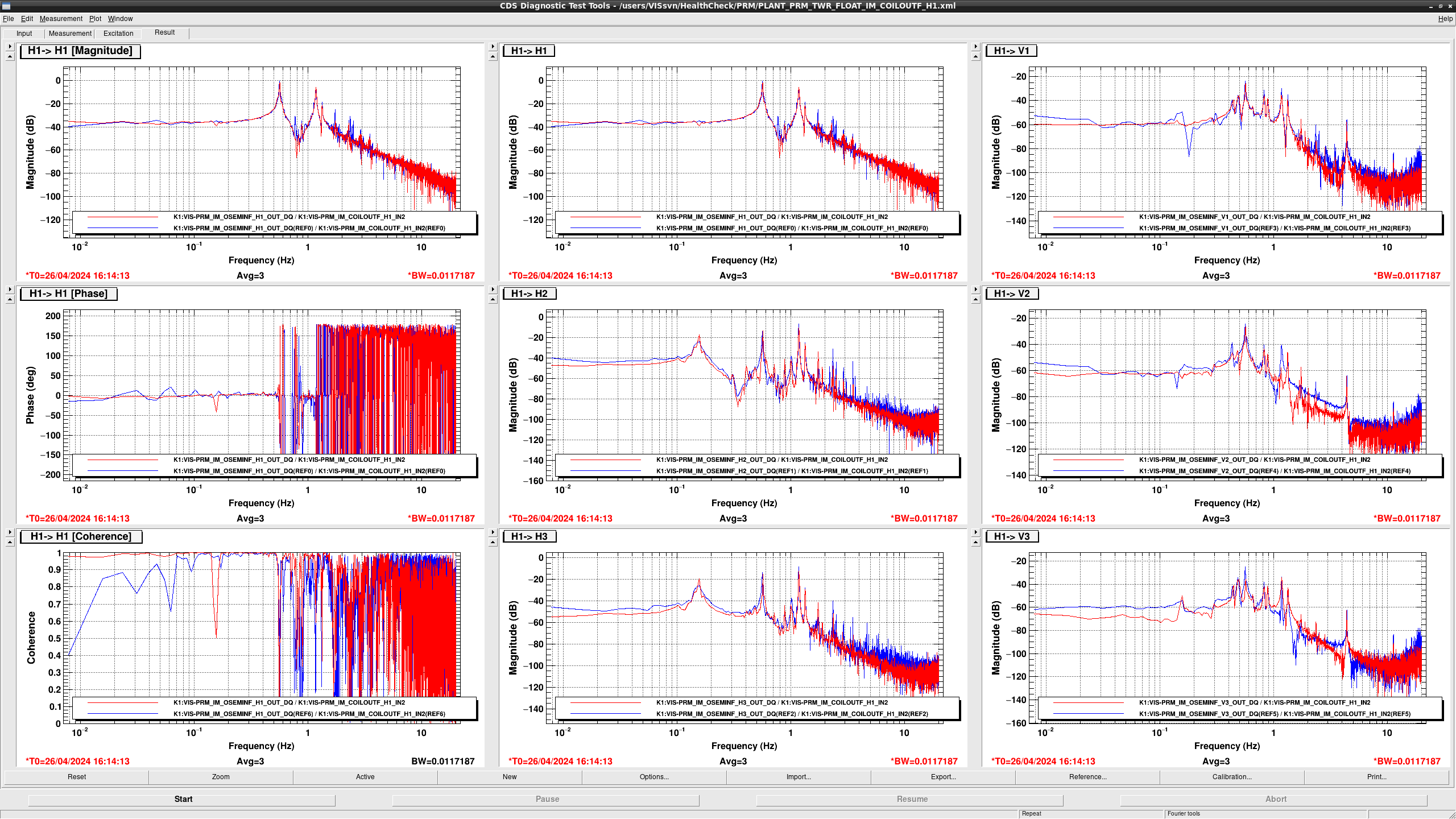
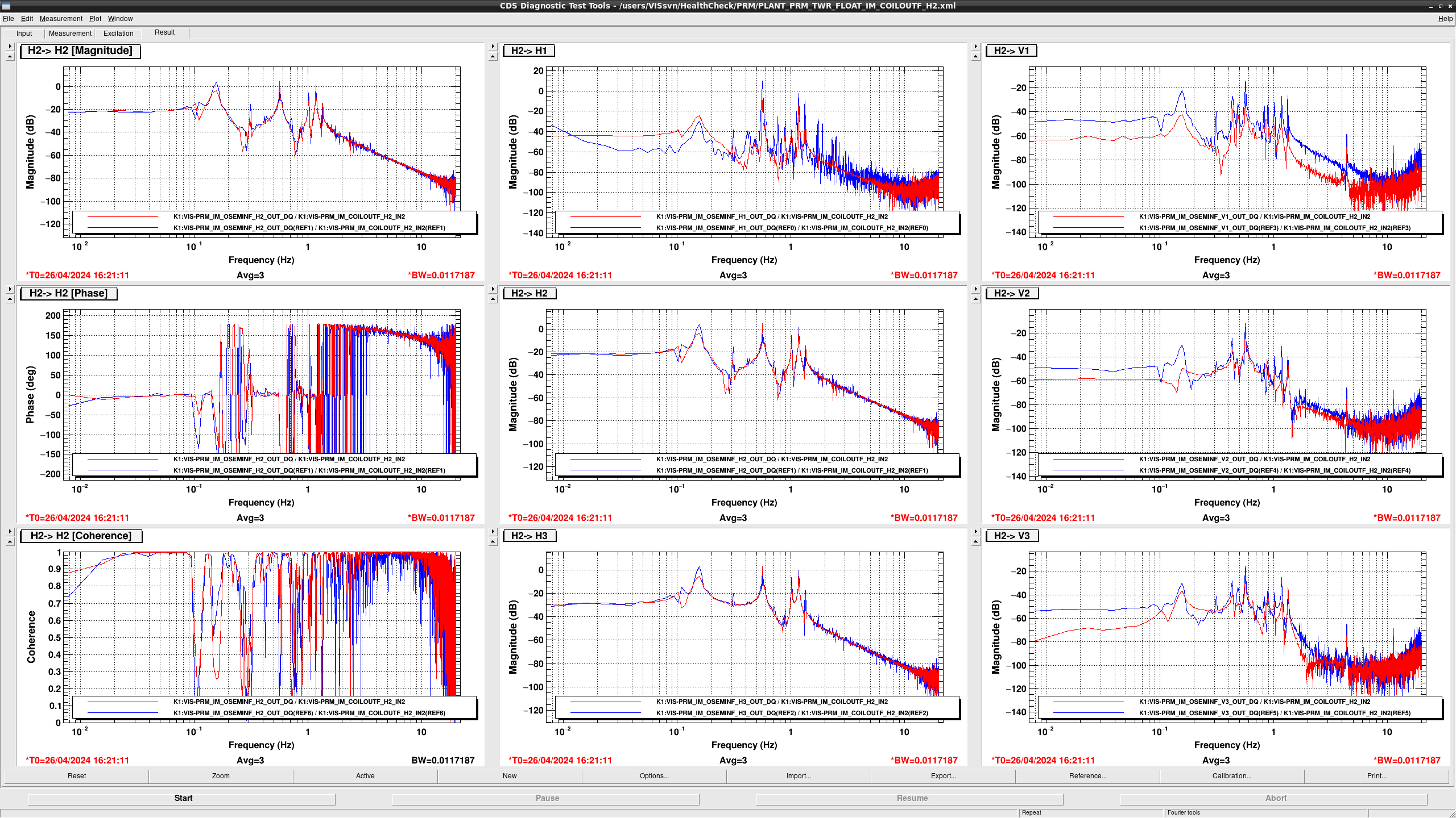
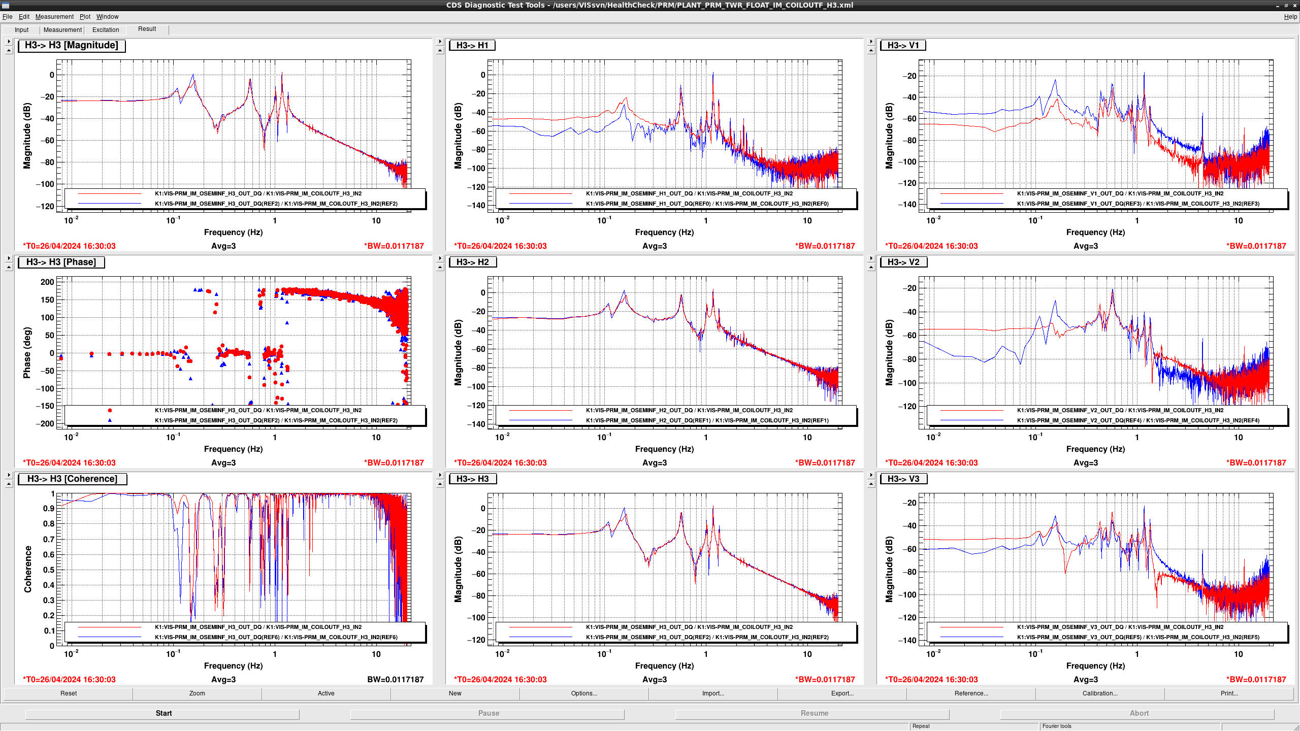
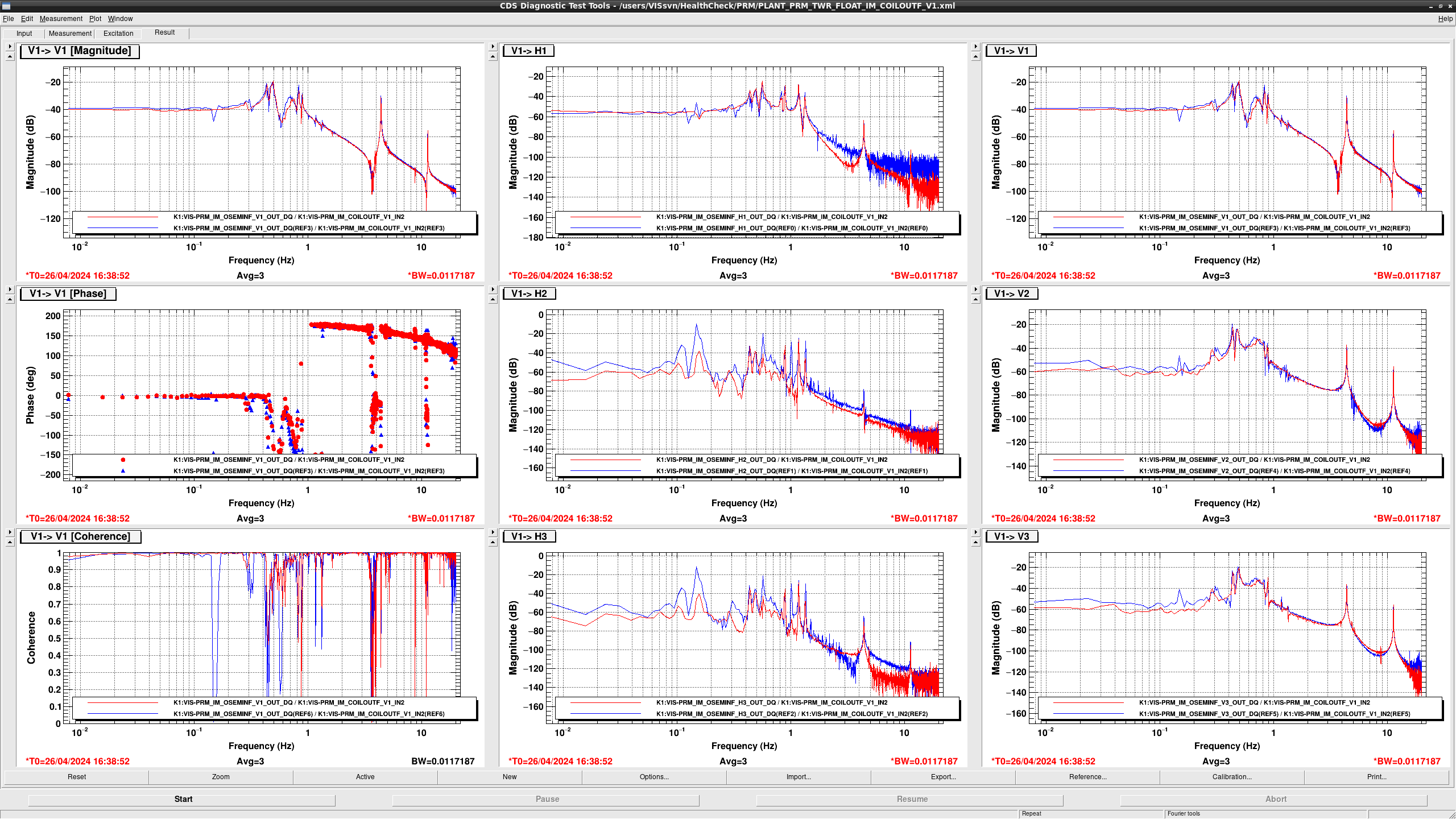
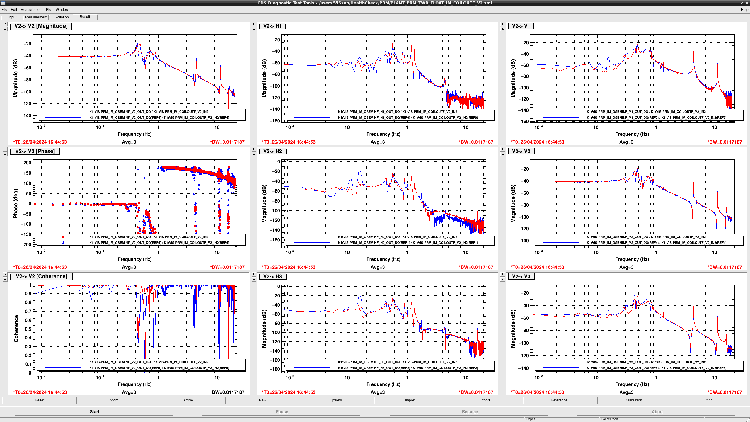
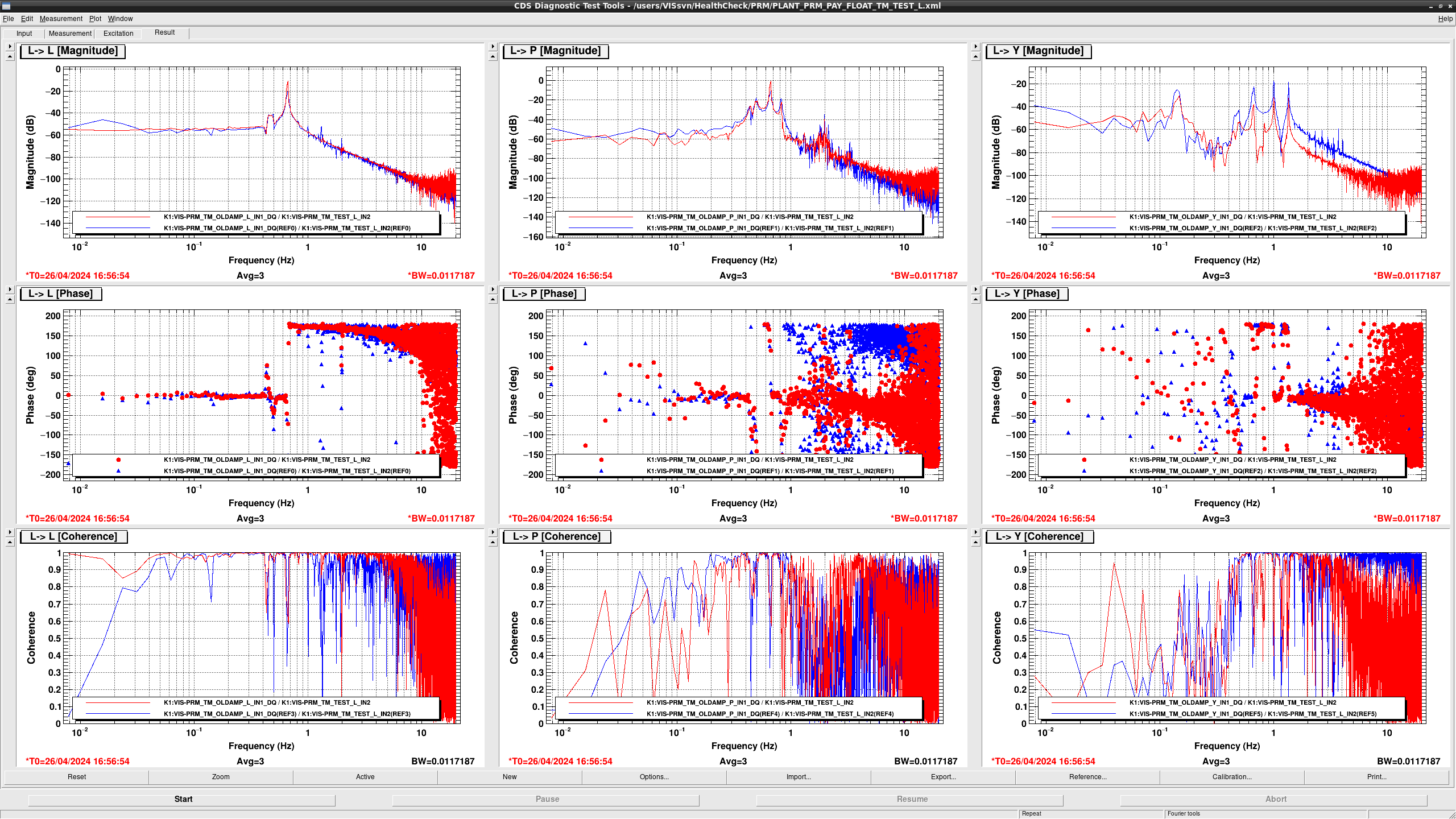
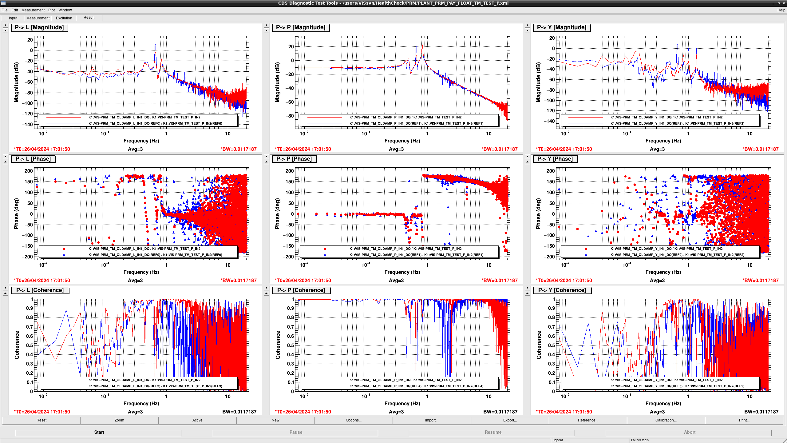
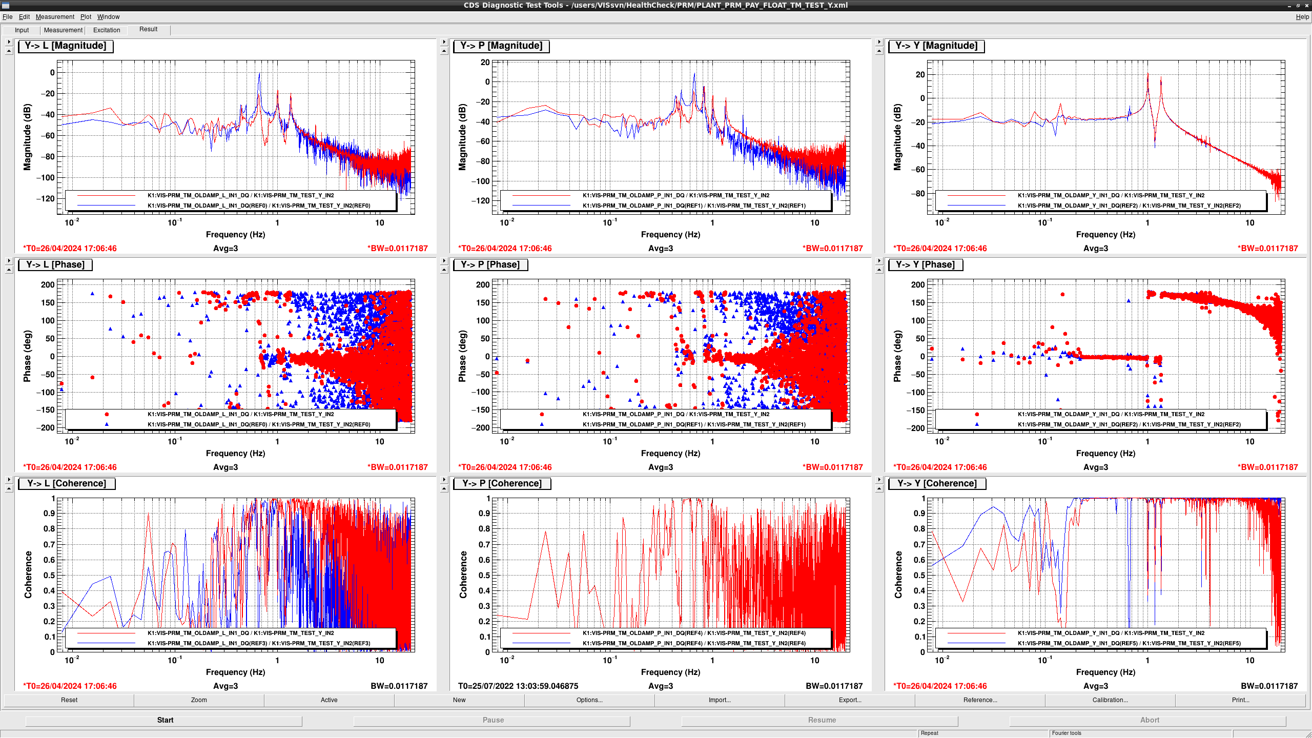
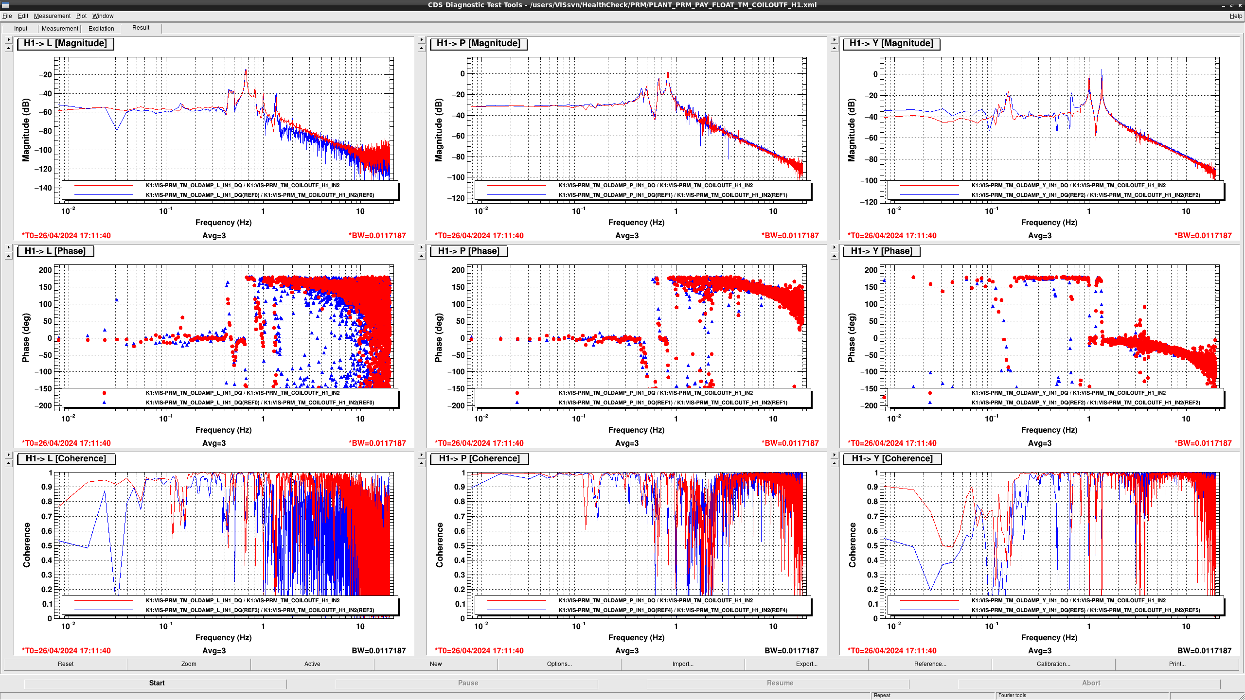
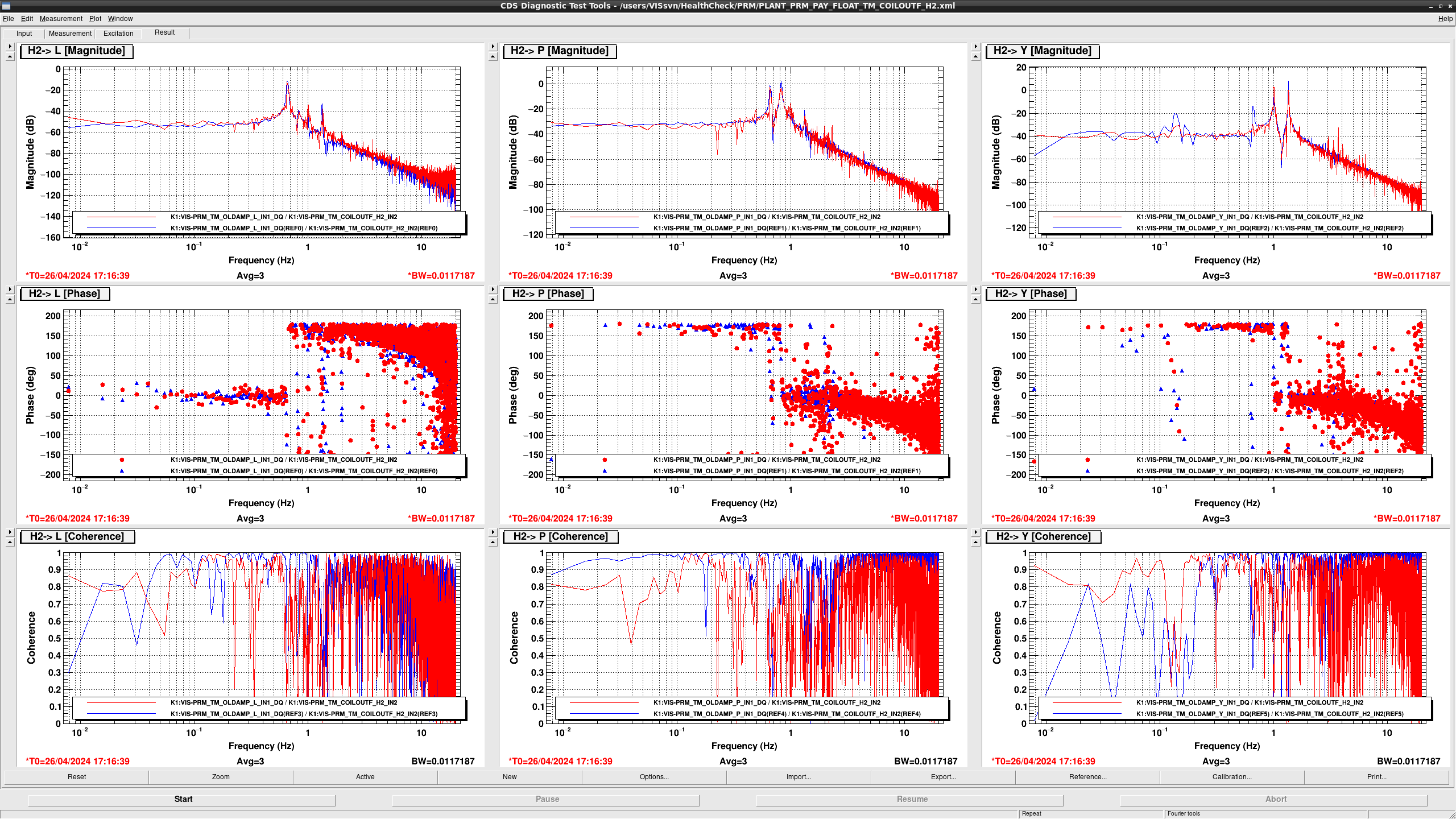
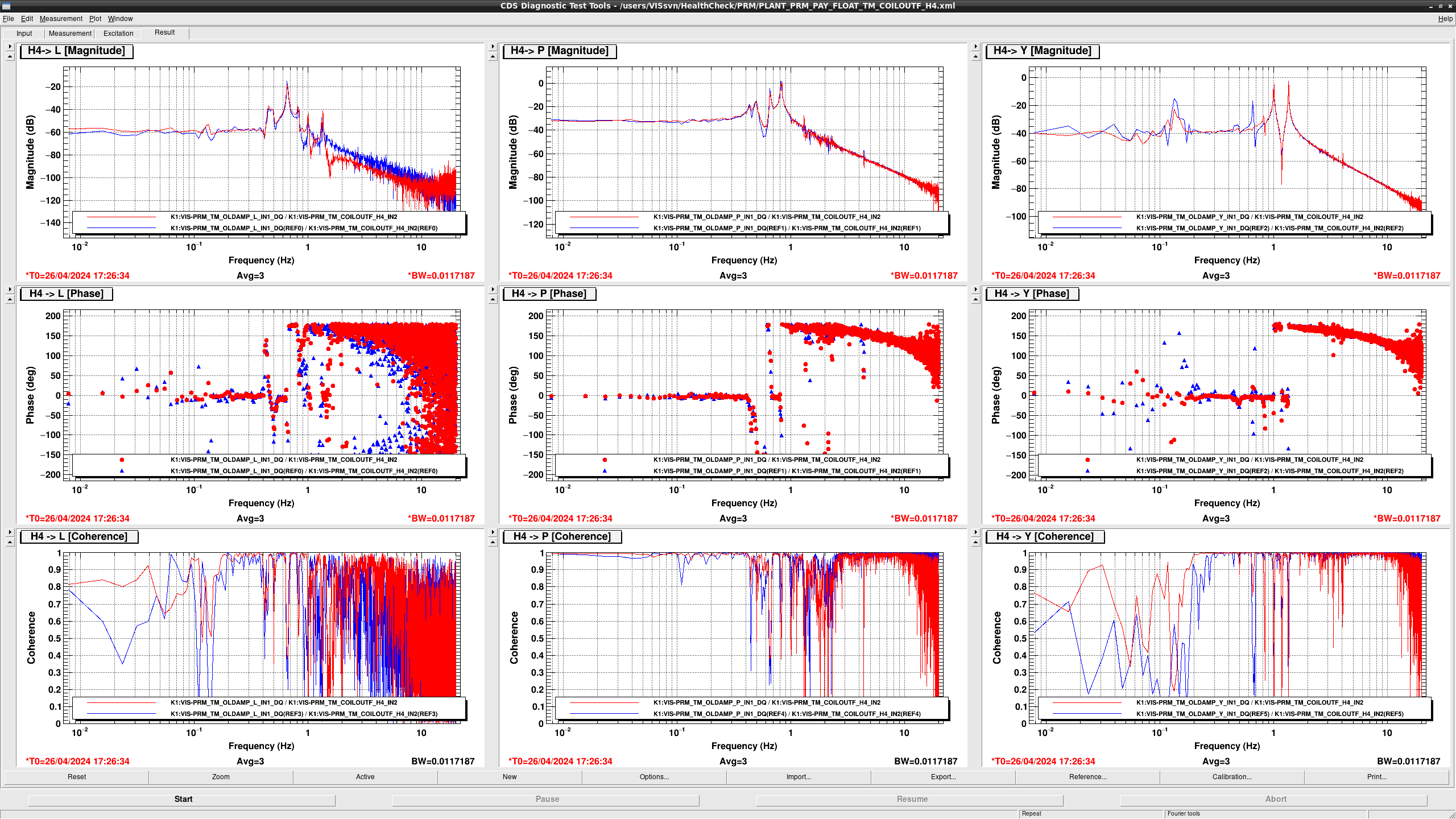
I checked all TFs of PRM.
All TF seem fine though resonant frequency of GAS filter is shifted slightly.
Following is an additional note, which is not problematic.
1. BF coil DoF measurement have a larger gain than before because of the calibration factor update (klog21311 and klog21315).
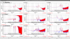

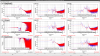


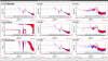
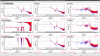
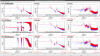
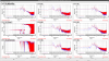


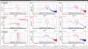
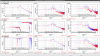
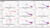

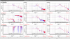
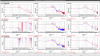
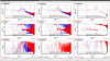
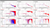
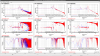
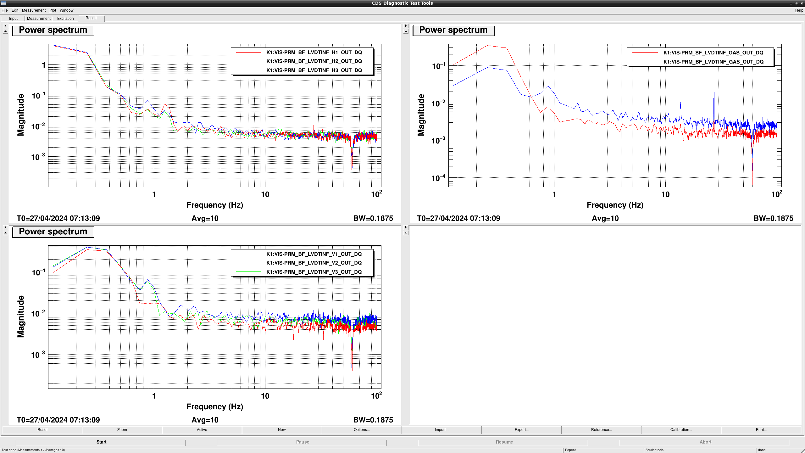
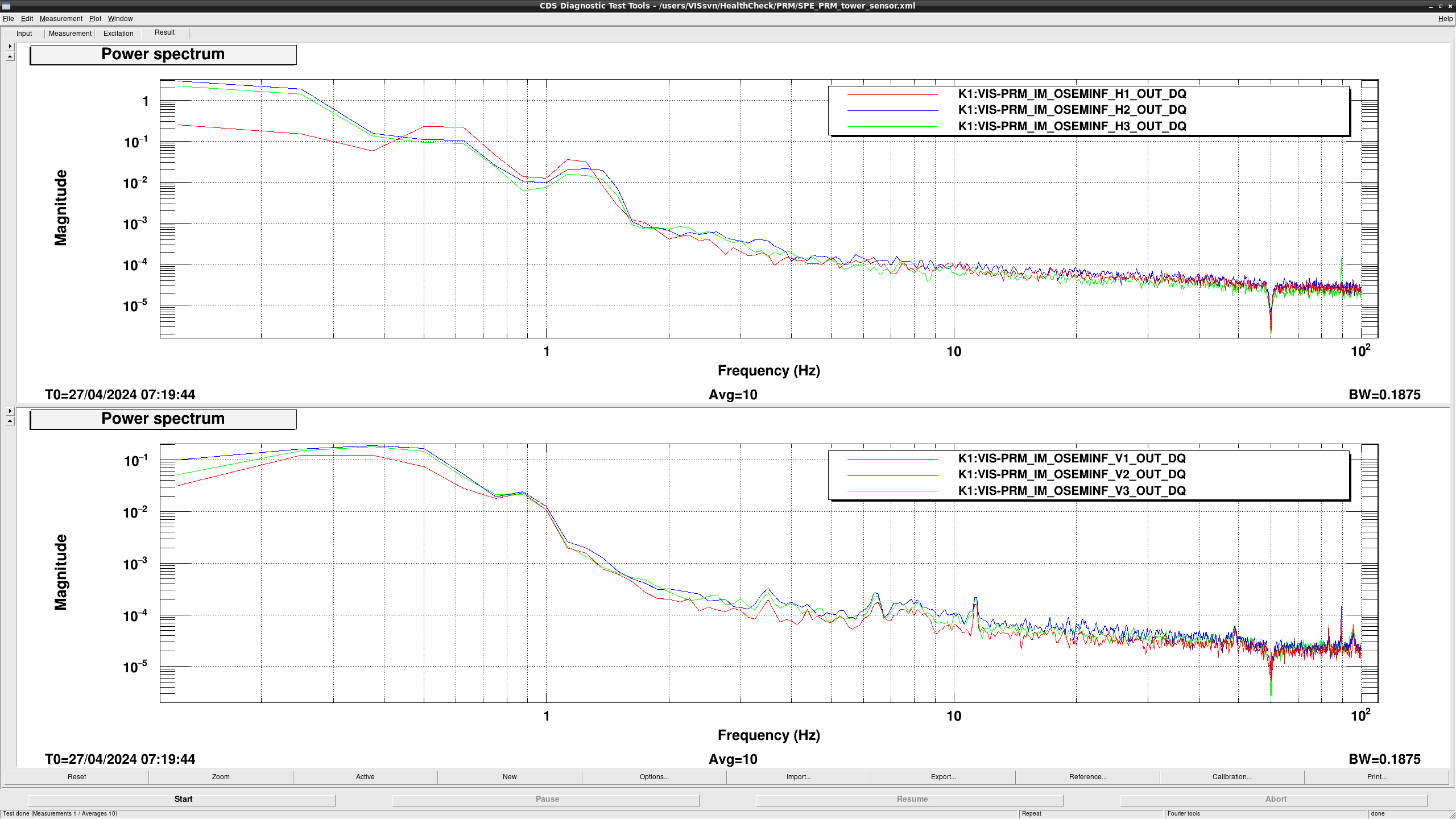
I measured the spectra of PRM LVDTs and OSEMs (fig1, fig2)
All seem fine.
IMC LSC was often failed when holding the output of MCL feedback.
Since MCE actuator efficincy increased by a factor of 3 due to thechange of the magnet size, I added a gain of 0.3 at FM9 (gain) of IMC-MCL_SERVO filter bank.
I performed finer alignment of X arm with ADSs.
Followings are the procedure:
1. X arm lock with both IR and GR.
2. Engage ADSs for PR3 by using GRX PD.
3. Engage ADSs for PR2 and IMMT2 by using IRX PD.
4. Move ITMX and ETMX so that beam spot on both mirrors are good.
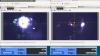
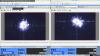
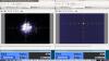
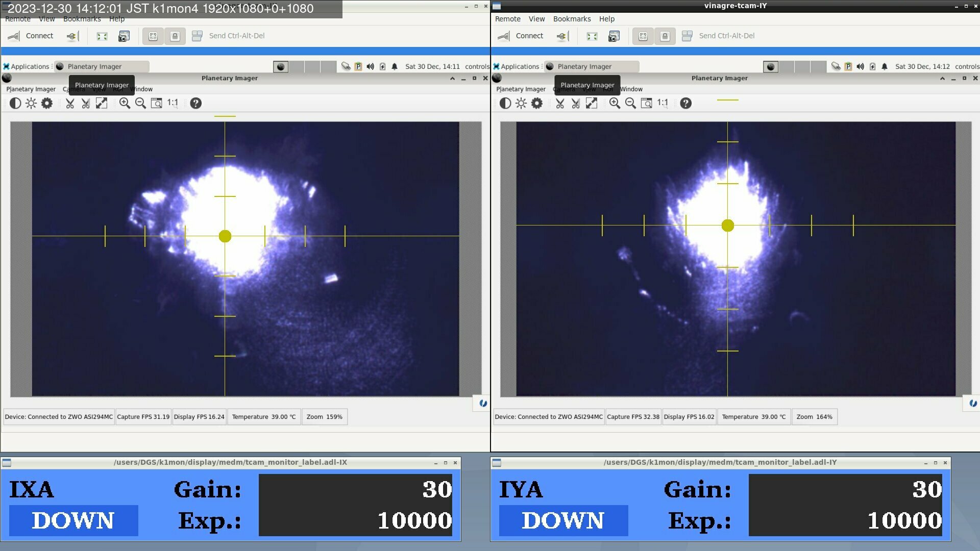
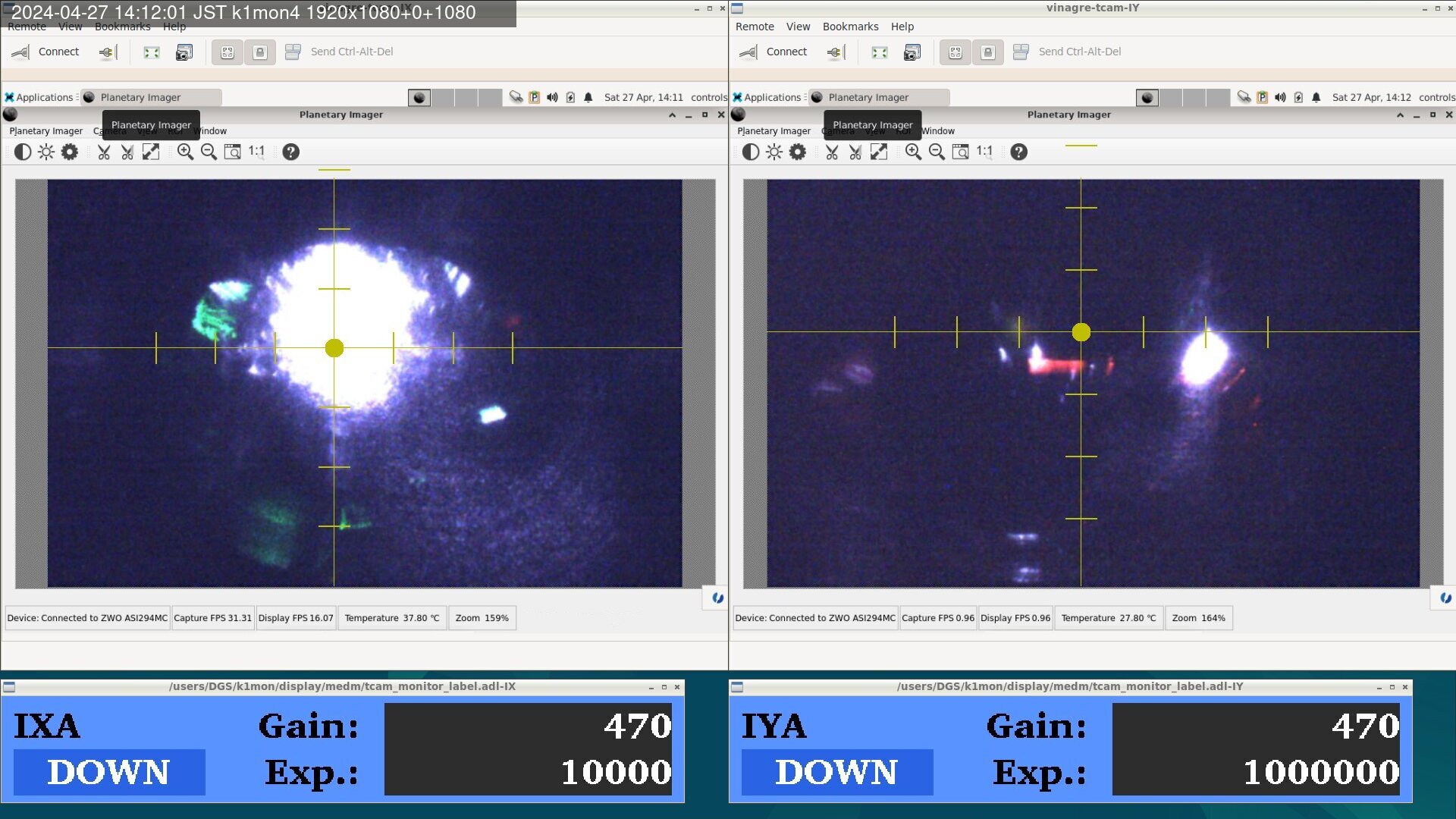
Left figure of fig1 and 2 show the beam spot on ITMX before the earthquake and now, respectively.
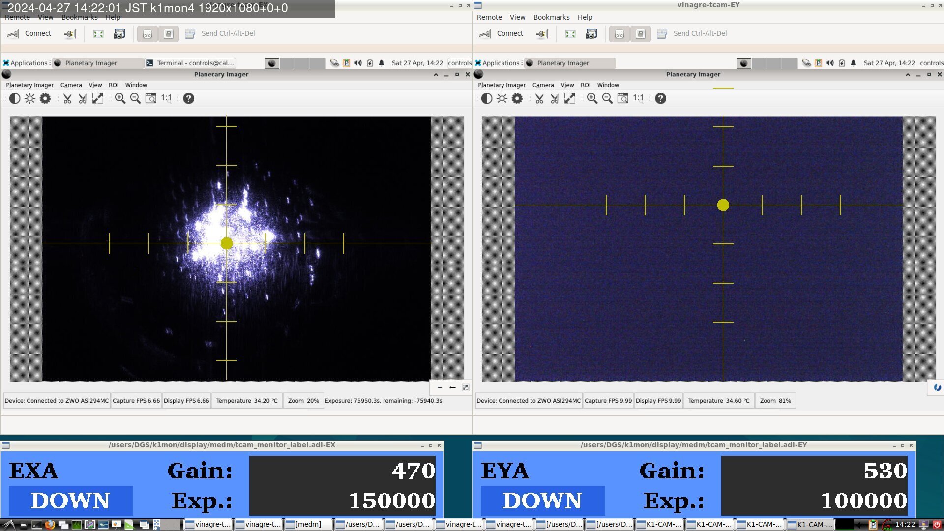
Left figure of fig3 and 4 show the beam spot on ETMX before the earthquake and now, respectively.
After the alignment, I recoarded the good OpLev values of IMMT2, PR2, PR3, ITMX, and ETMX.
Followings are the several notes we need to check.
1. IRX beam is not hit to the X arm trans IR camera.
2. GRX beam is shifted on the X arm trans GR camera.
3. We haven't checked the beam on TMSX, so I'm not so sure ADSs work fine (at least, trans power was increased thanks to ADSs, though).
4. IRX and GRX normalized transmission is around 0.7-0.8 now. I'm not so sure this value is due to the bad alignment, bad finesse, or clipping somewhere (GV between BS-IXC, GV between EXC-TMSX, optics on TMSX, and so on).

[Yokozawa, Ushiba]
During the work, we found that the OpLev beam was clipped by te RM, so we moved injection beam and in-vac mirror slightly to avoid cipping.
After rearrangement of the optics, we performed OpLev beam centering.
Hirata, Akutsu on 26 Apr 2024; following 29342.
Summary
Checked if ghost beams were within the relevant beam dumps in IMM chamber.
Setup
The same as 29342 basically. Plus, request IMMT1 Guardian to PAY_FLOAT, as we need to check behind IMMT1 and cut/shut the oplev beams.
Details
For the reference drawing, see Fig. 1 of 21578 (finalization in 2022); but I think we would need the newer version of this...
Behind IMMT1
Behind IMMT1, there are a pick off mirror (IMMT1T-POM) and a beam dump, while there are four transmission beams:
- Forward IMMT1 transmission. Most of this is reflected by IMMT1T-POM within the chamber, and becomes ISS beam. A part of this, or transmission of IMMT1T-POM is used as IMMT1T beam for IMC-ASC.
- Backward IMMT1 transmission. Most of this is reflected by IMMT1T-POM as well, but to be dumped later within the chamber (shown later). A part of this would trasnmit out of the chamber throught a viewport, and should be around IMMT1T beam; hopefully properly dumped on the in-air optical bench.
- IMMT1 AR reflection (forward); this is an IMMT1 AR reflection of "1" above. To be dumped here.
- IMMT1 AR reflection (backward); this is an IMMT1 AR reflection of "2" above. To be dumped here.
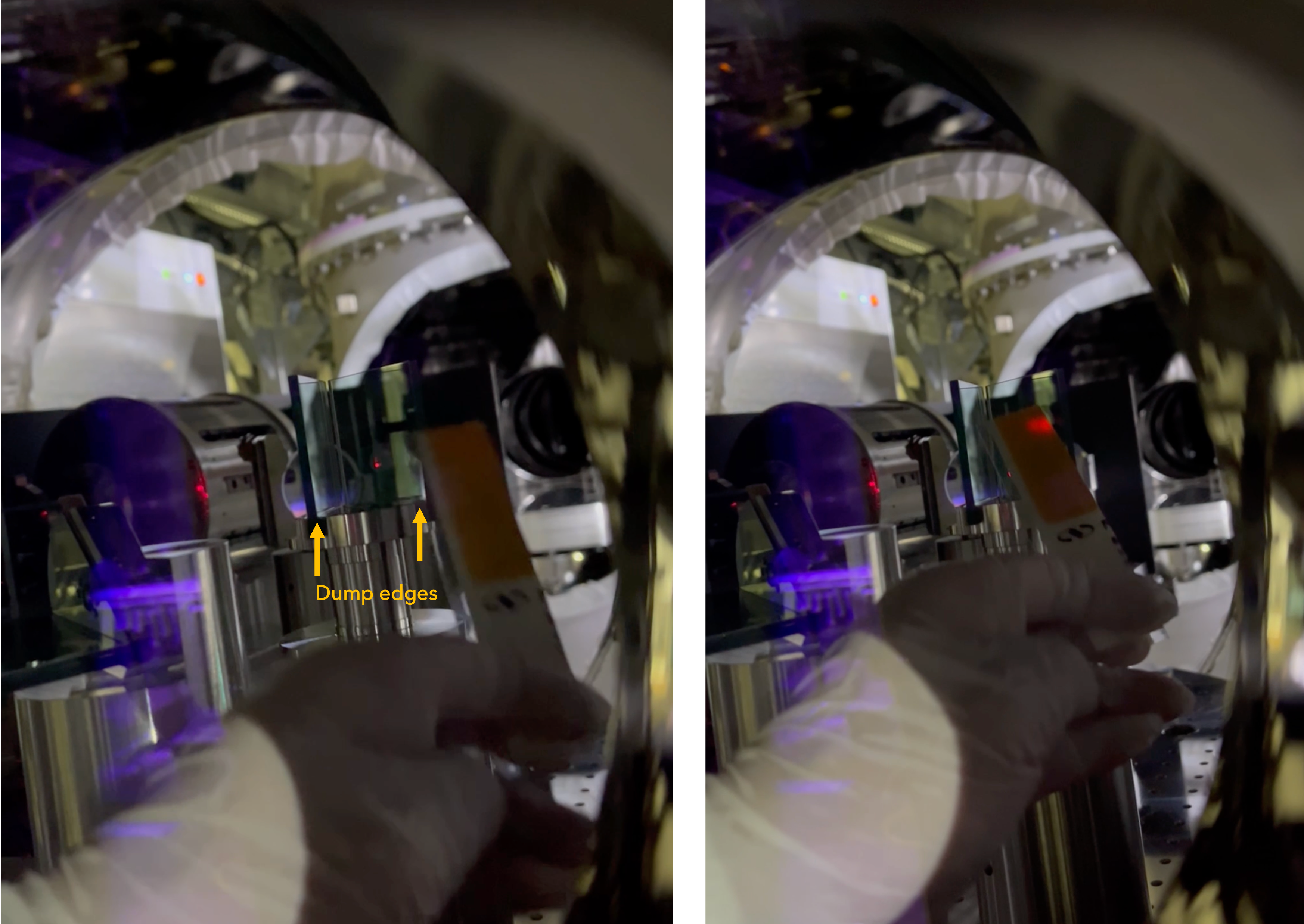
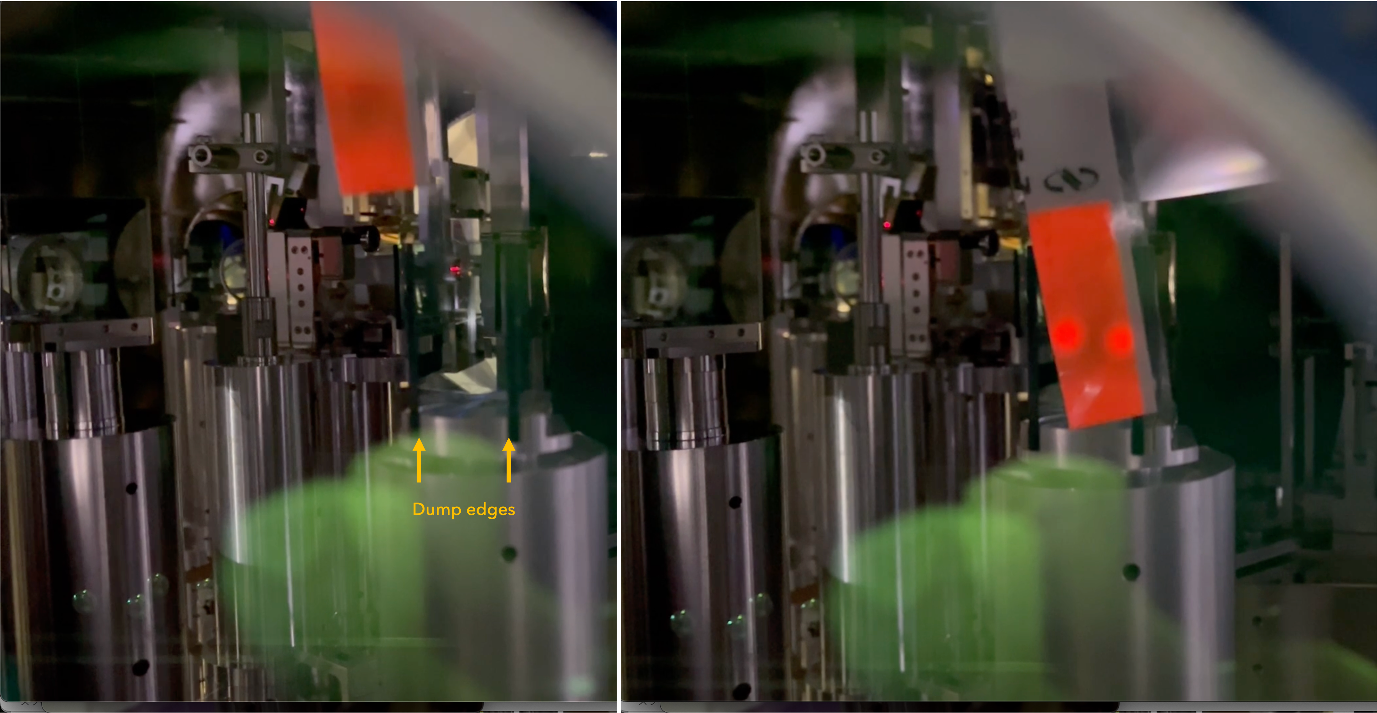
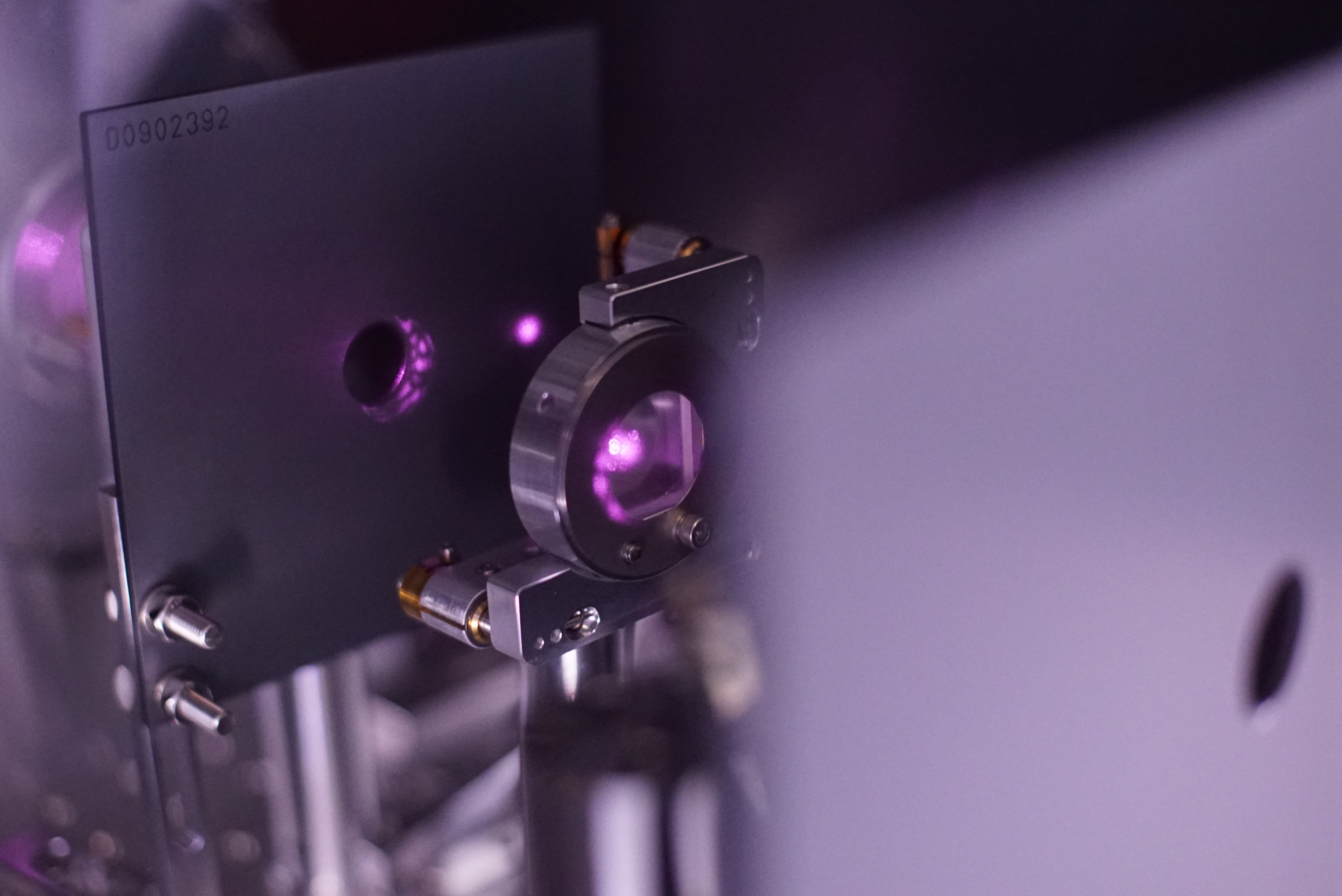
Fig. 1 shows the beam "1" and "2" mentioned above are within the IMMT1T-POM (pick off mirror). Fig. 2 shows the ghost beams "3" and "4" mentioned above are within the beam dump.
Backward beam through IMMT1 and reflected by IMMT1T-POM
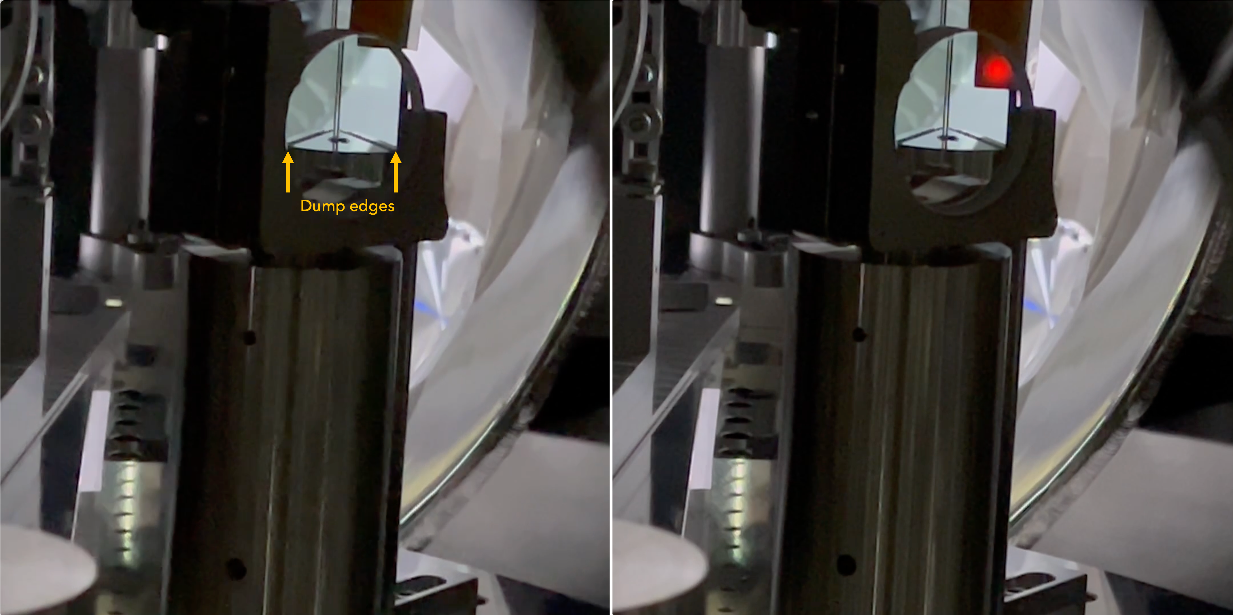
Fig. 3 shows the beam "2" mentioned above is dumped by the relevant beam dump. Due to the mirror-like surface of the structure, a vertual image of the sensor card and the ghost beam can be also seen; please not confused if there might be two ghost beams; it seems only one GB.
ISS beam reflected at the relevant viewport window
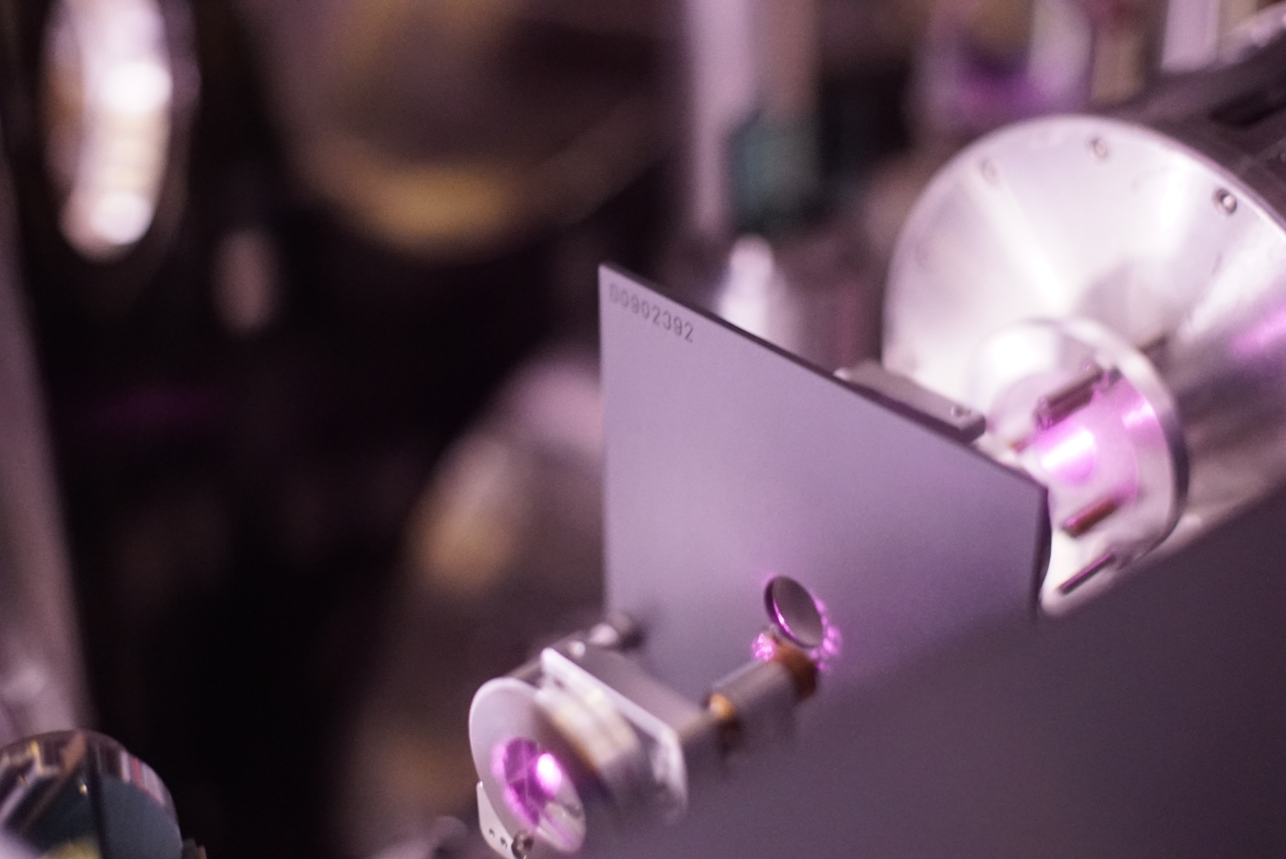
Fig. 4 shows a (actually two degenrated) ghost beam generated at a viewport window through which a beam for ISS passes. In theory there should be two ghost beams, but due to the narrow separation of the two beams, they can be caught with a single beam dump.
Note
- The other beam dumps and shields were already checked the other day. For example, see Fig. 8 of Day 6 (29334).
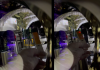
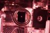
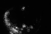
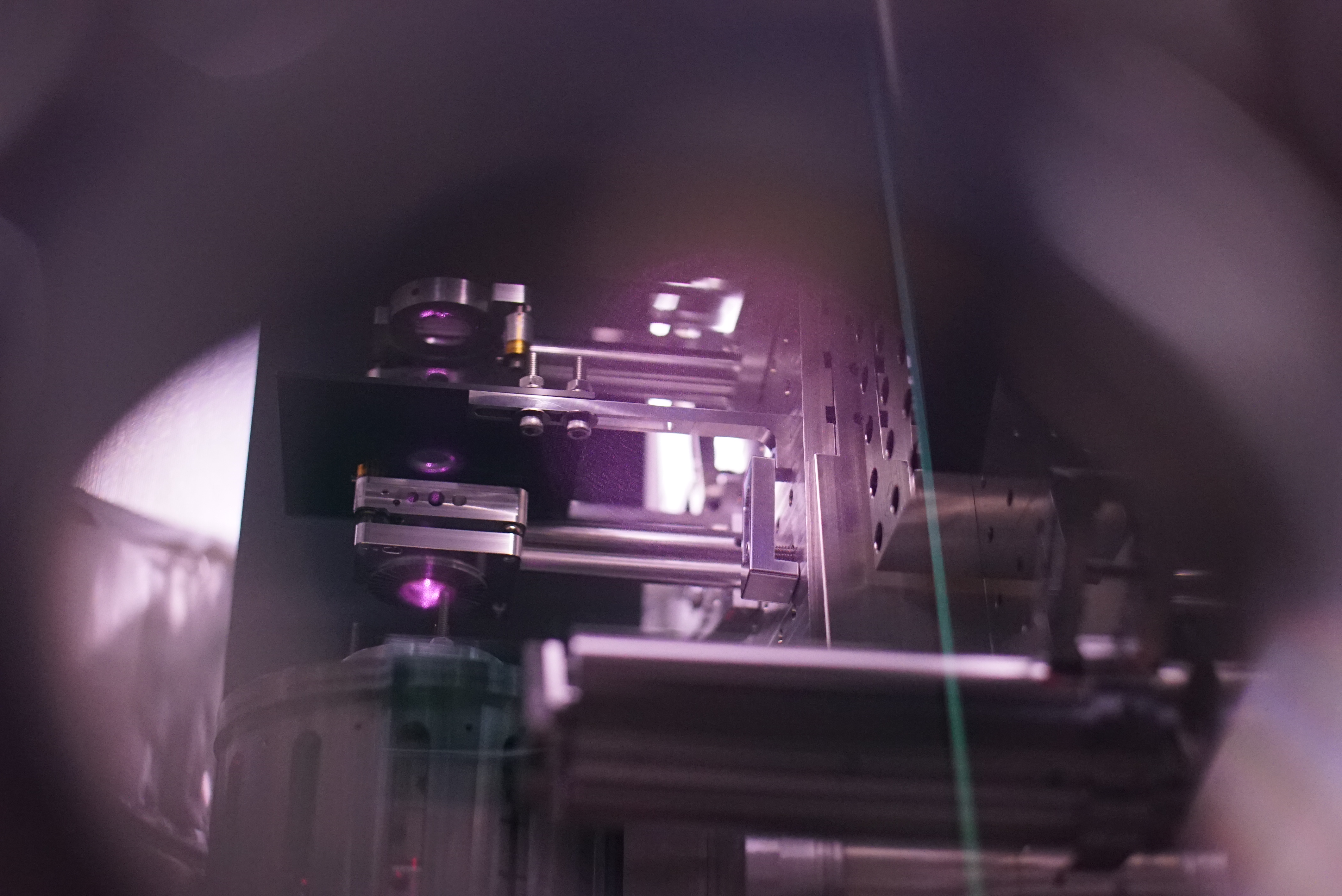
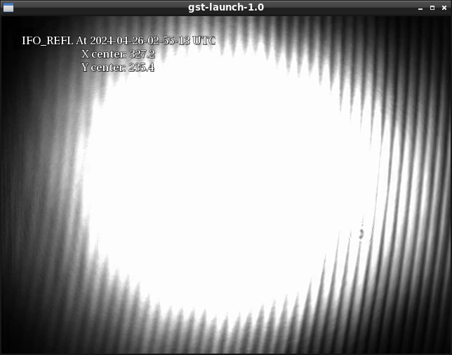
- Different from IFI chamber, IMM chamber is not so shining when I saw it with IR camera. By the way, interestingly, Fig. 5 shows something above PRM is shining in IR. Fig. 6 was taken after Fig. 5, and maybe these are from OSEMs. Even when we shut the PSL IR beam, these IR still there.
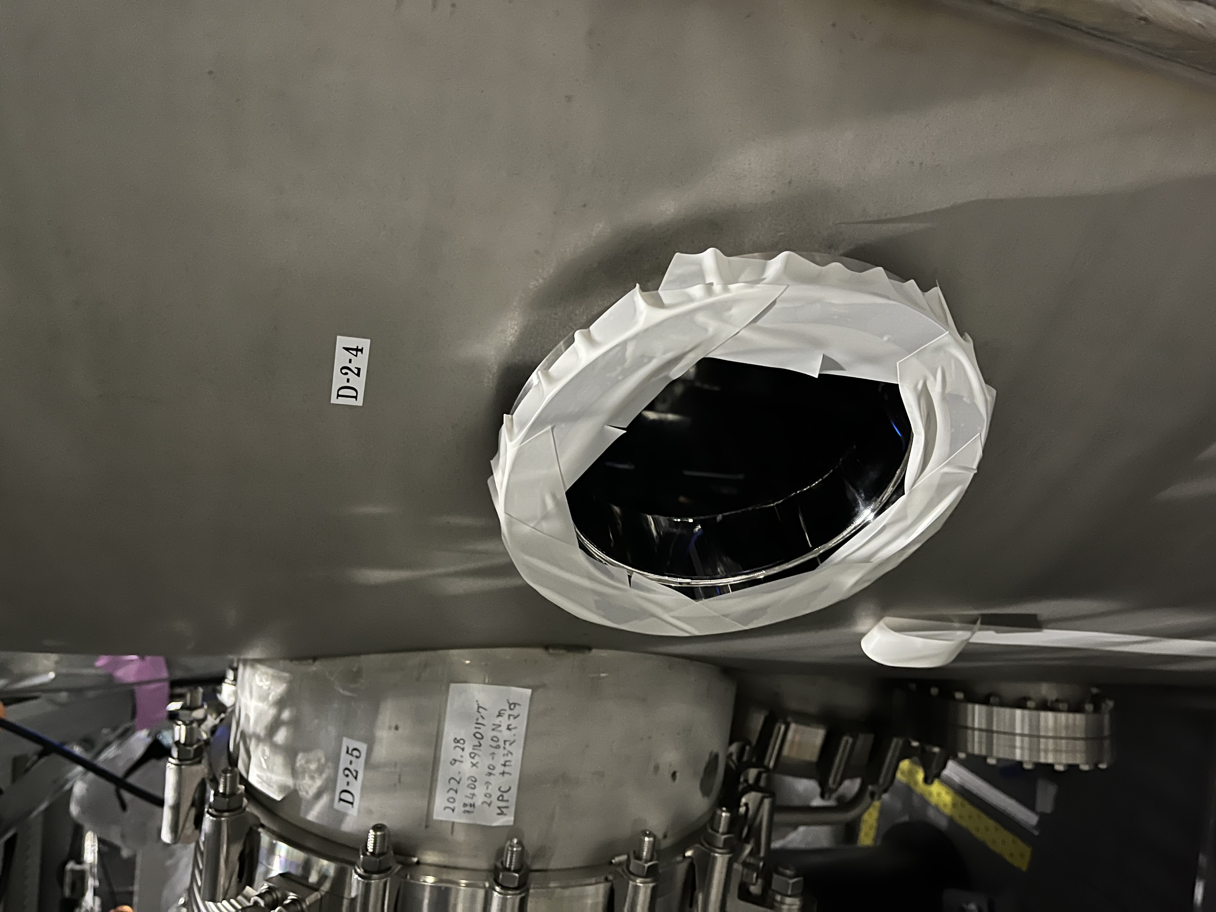
- For accessibility, we newly detached a blank flange D-2-4 of IMM chamber (Fig. 7)


Hirata, Akutsu on 26 Apr 2024; following 29334; also refer to some historical record in 2022's finalization Day 1, 2, 3, 4AM, 4PM, 5, 6, and 7.
Summary
Checked if ghost beams were within the relevant beam dumps in IFI chamber. Found some spread stray field but left regretfully today.
Setup
- Request PROVIDING_STABLE_LIGHT to IO Guardian, then request HOLD_ALIGNMENT to IMC Guardian.
- IMMT1 and 2 -> ALIGNED
- PRM -> LOCK_ACQUISITION so that backward light beam from PRM can be seen at the same time.
- Don't hesitate to monitor IMMT1T, POP_FORWARD, and REFL.
Details
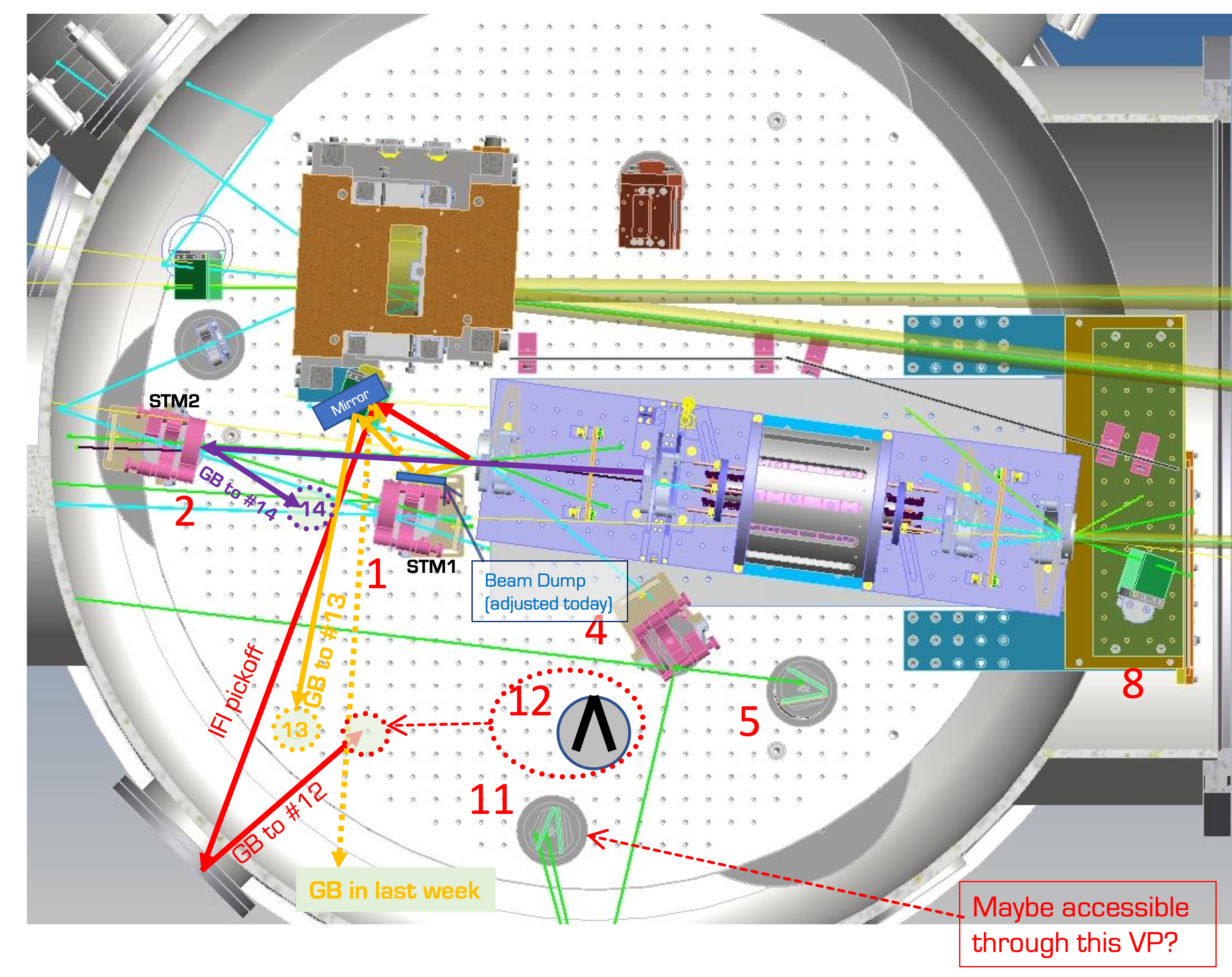
Firstly see Fig. 1, which is the same one as Fig.1 of 21655, Day 4 in 2022.
Around STM1
Around STM1, There are four beam dumps;
- a KG5 glass behind STM1
- a KG5 glass at the +Y side of STM1
- a beam dump (nameless) located above STM1 as in 22084; made of SiC.
- a beam dump #14 below STM1; made of SiC.
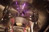
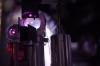
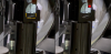
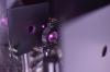
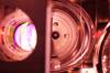
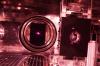
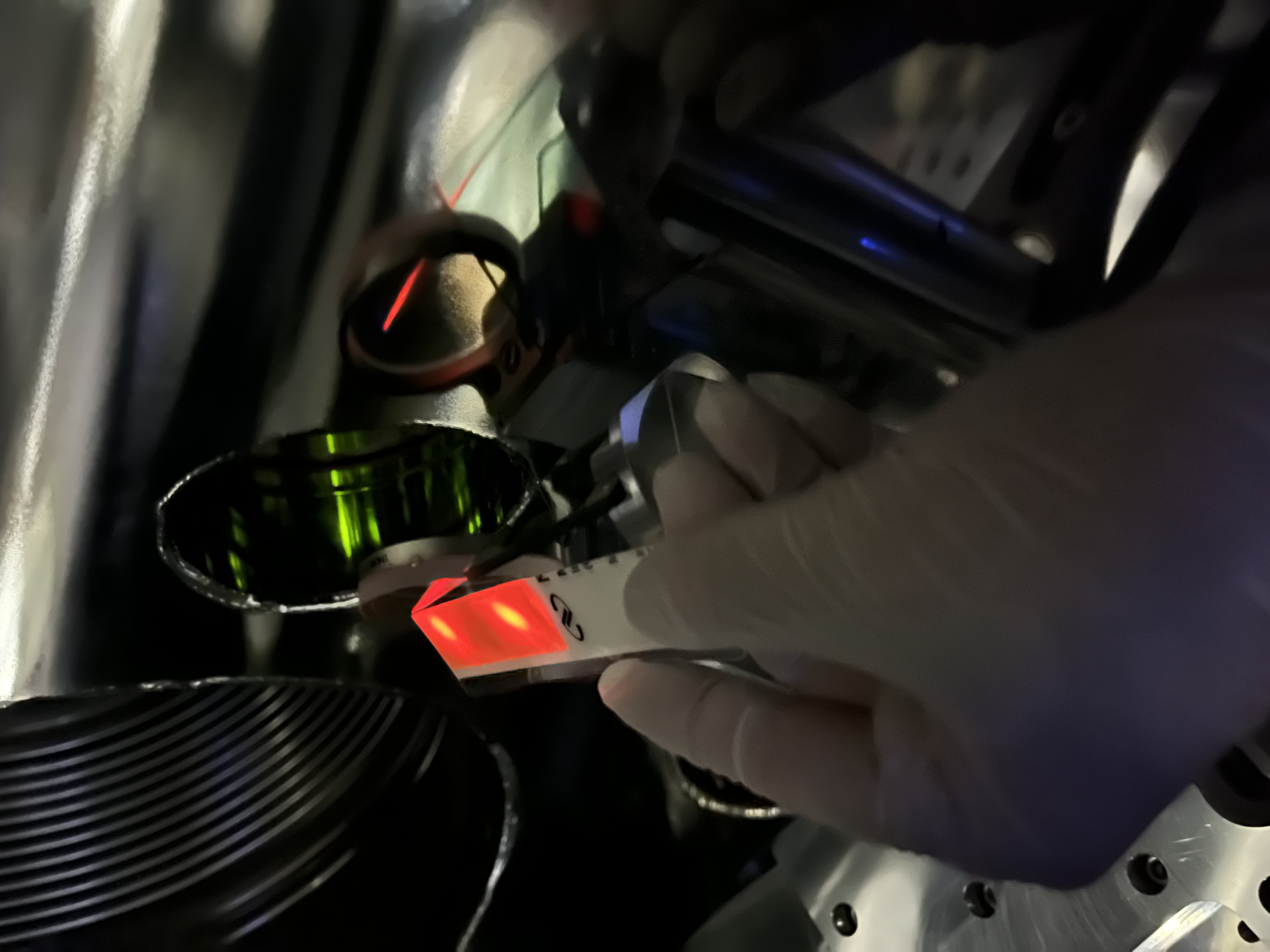
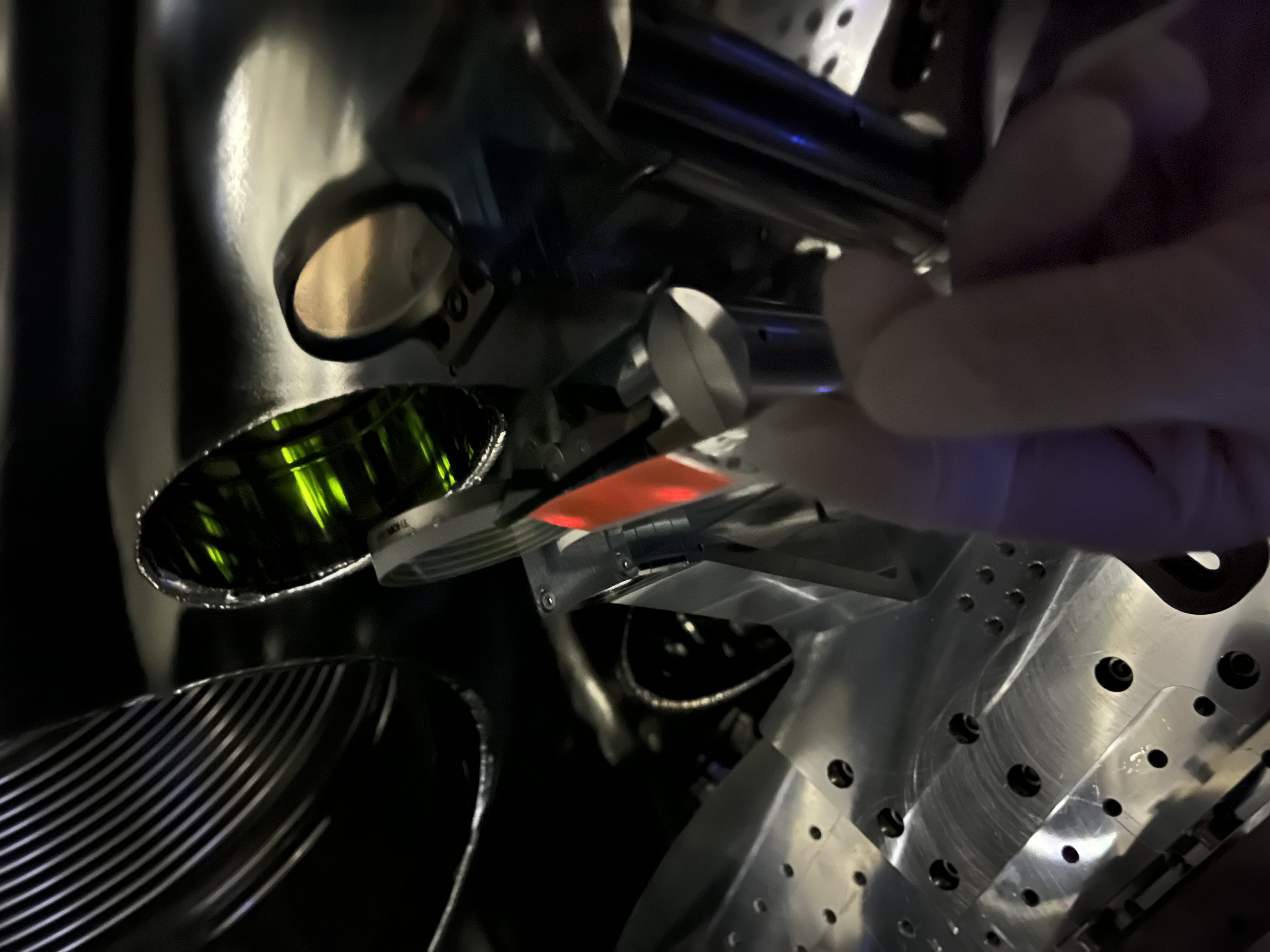
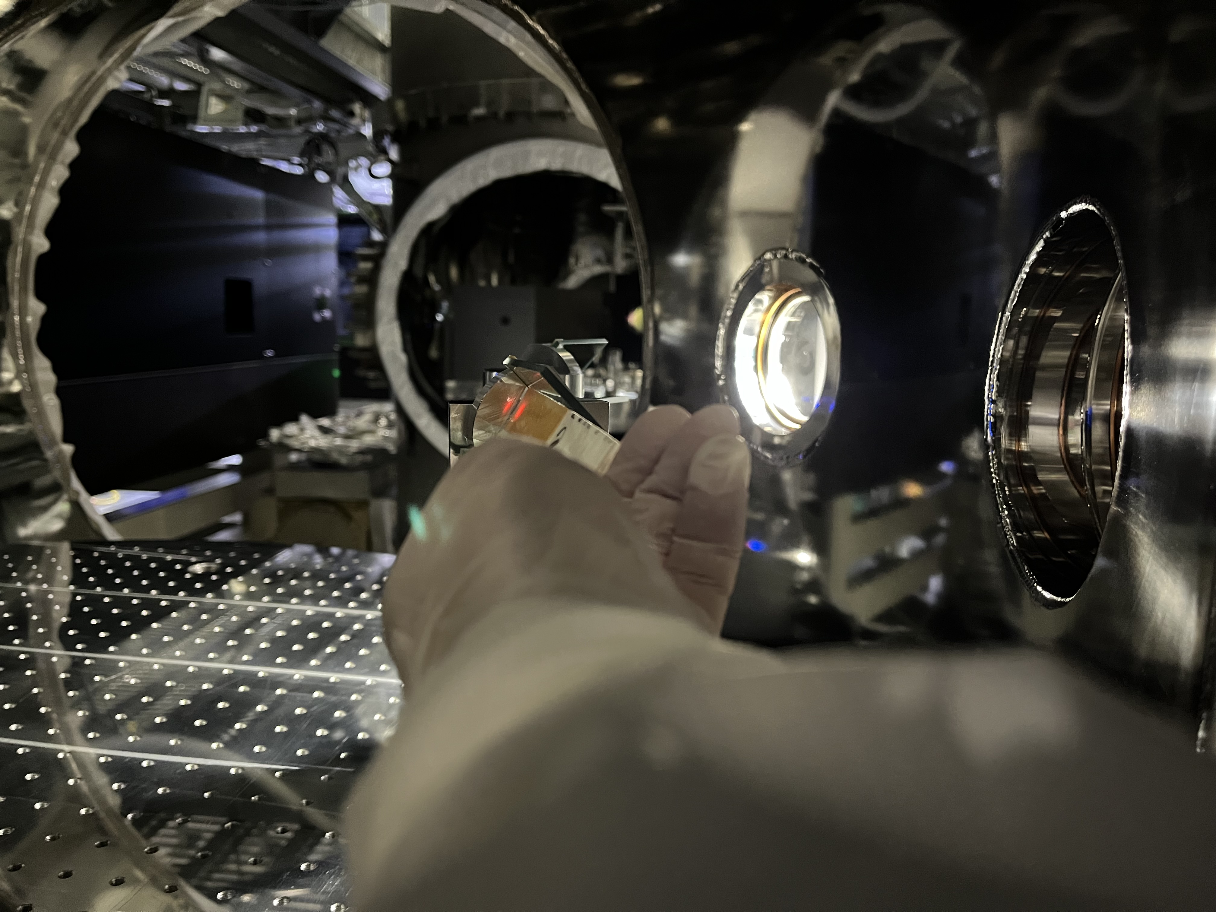
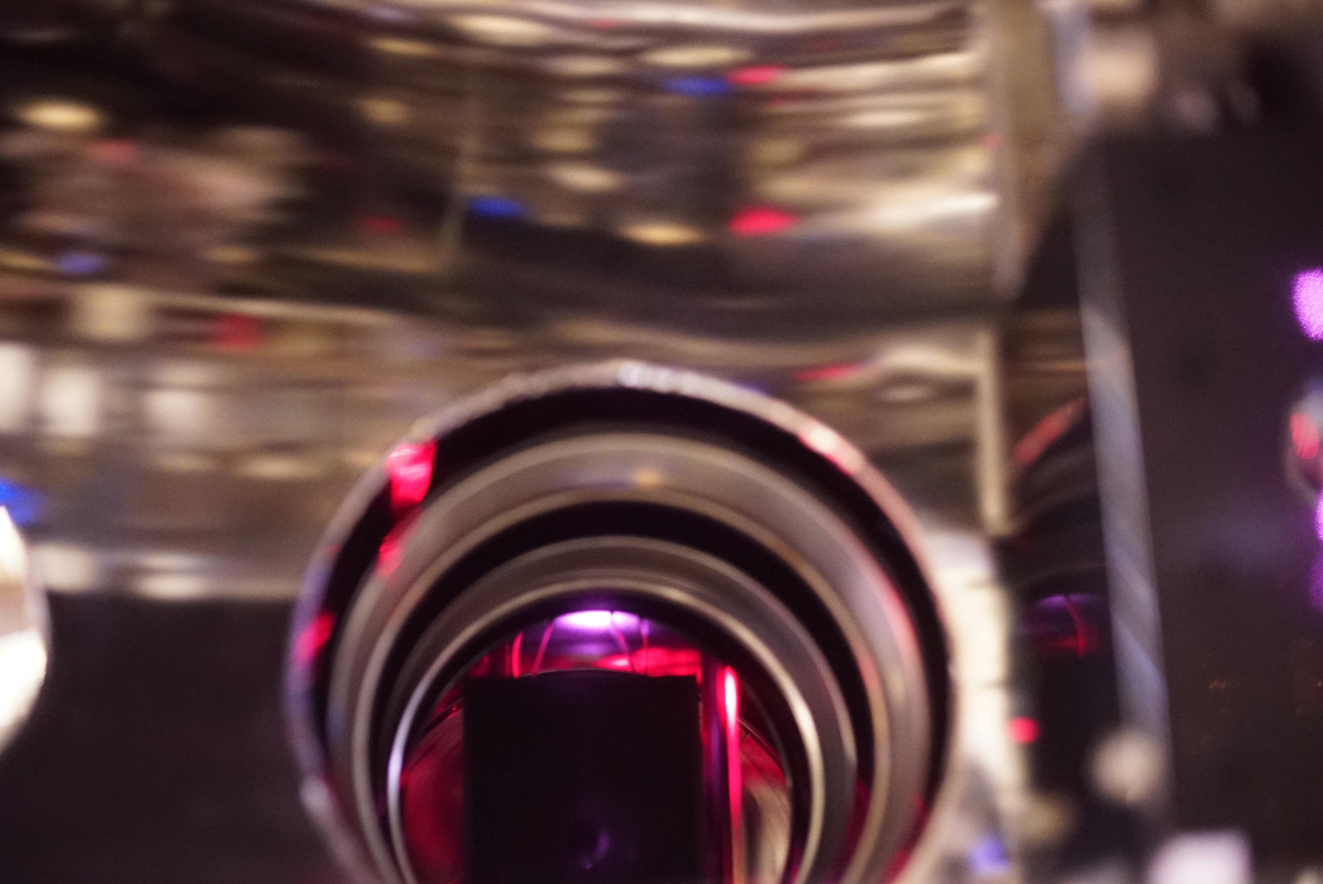
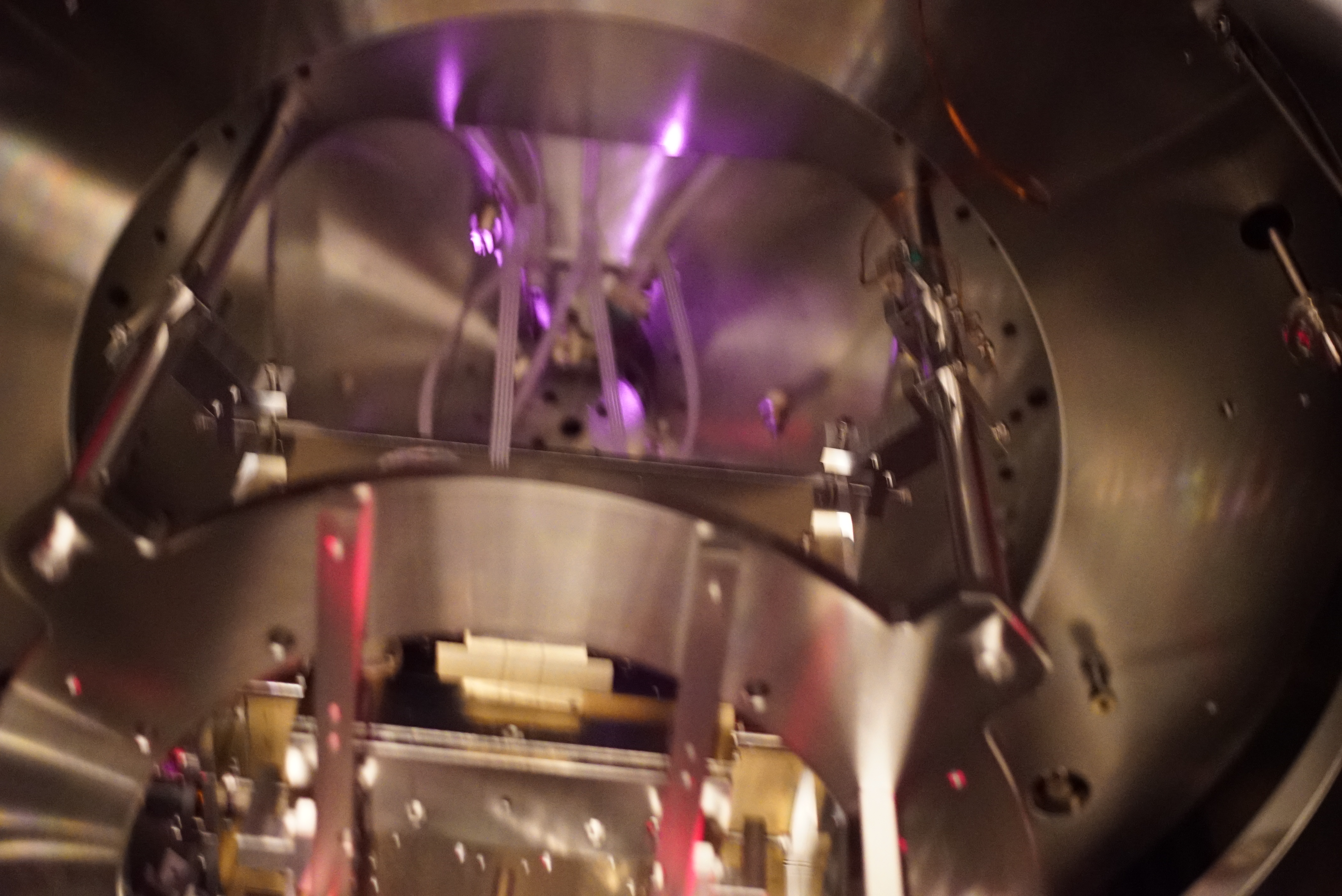
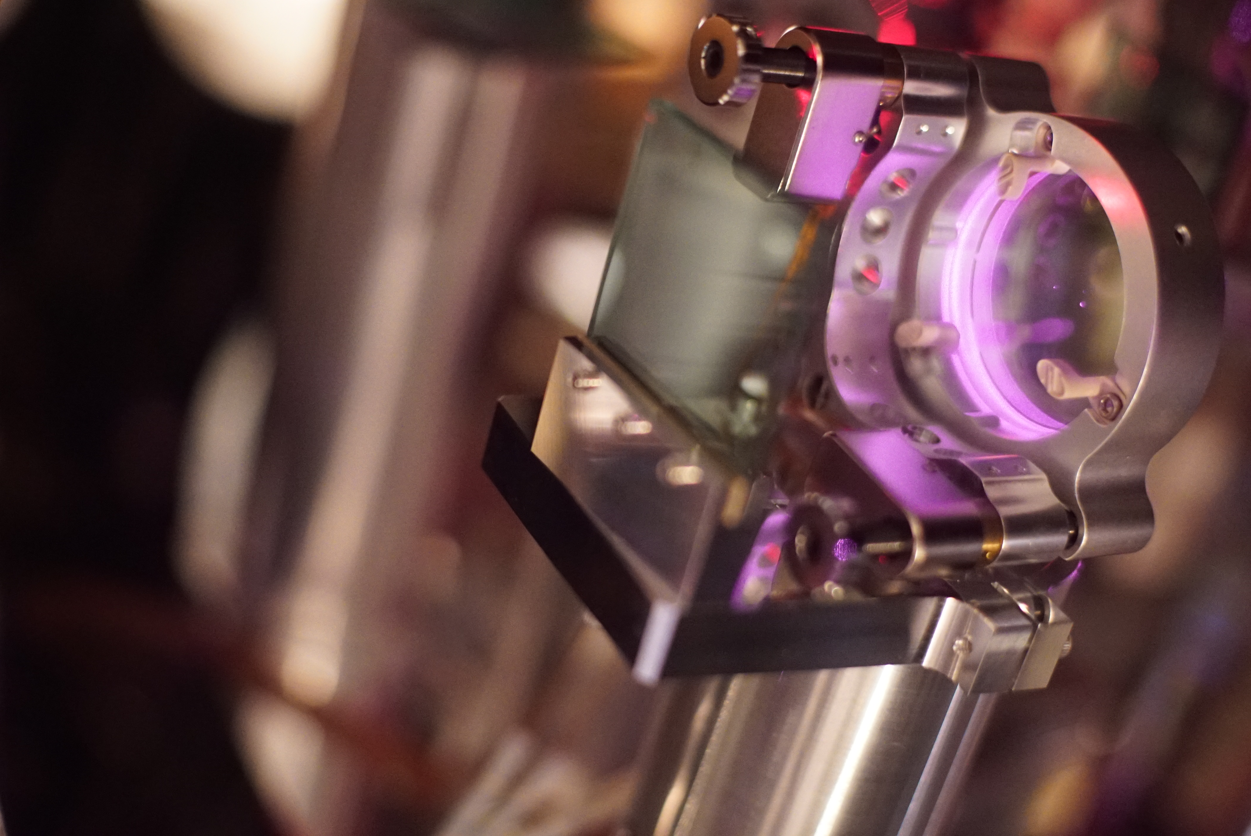
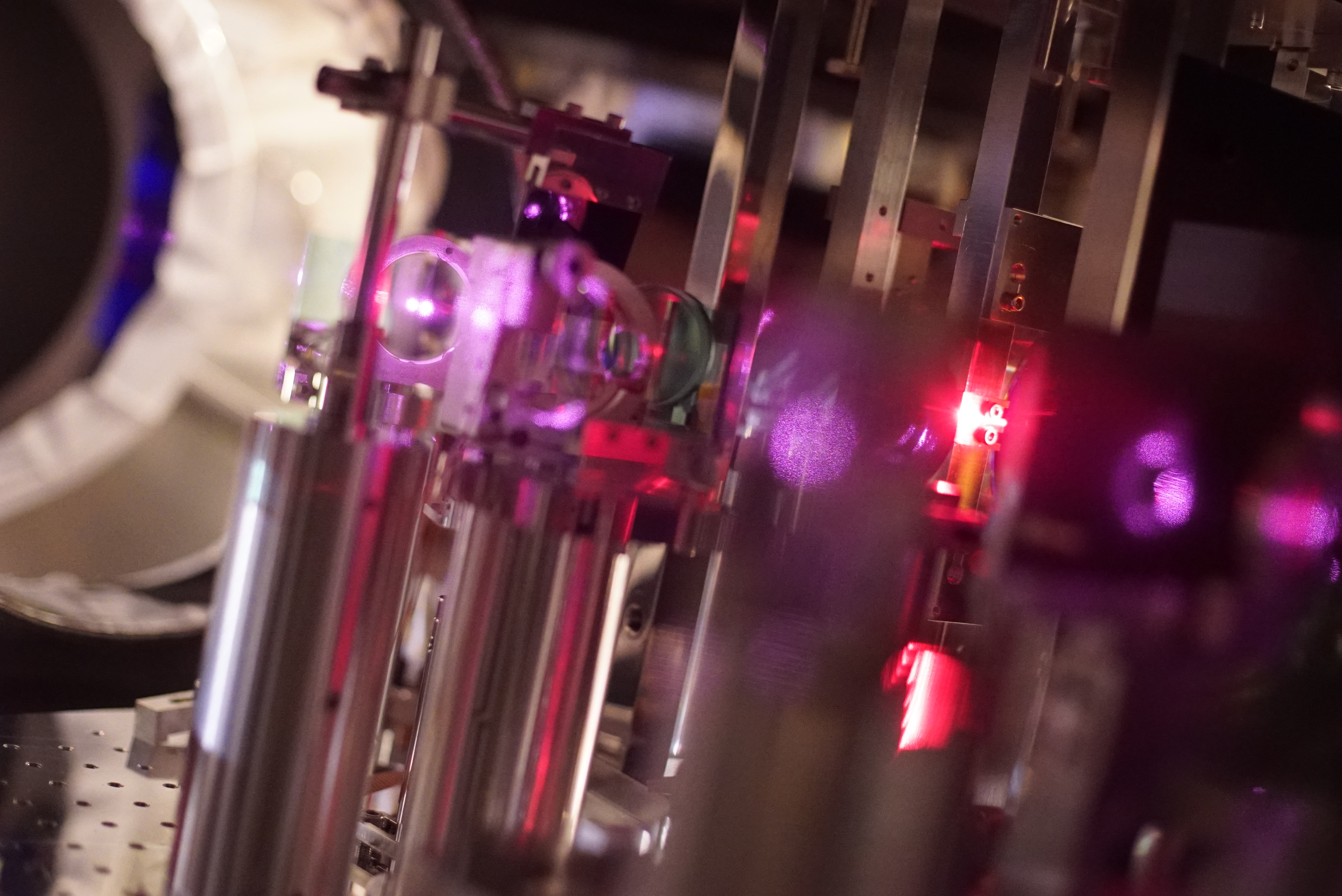
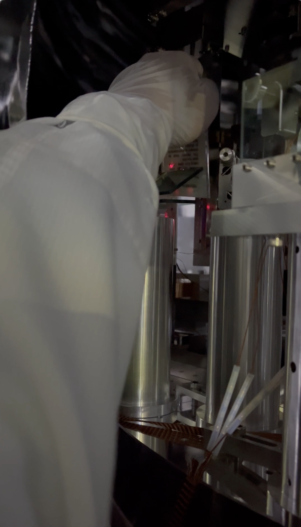
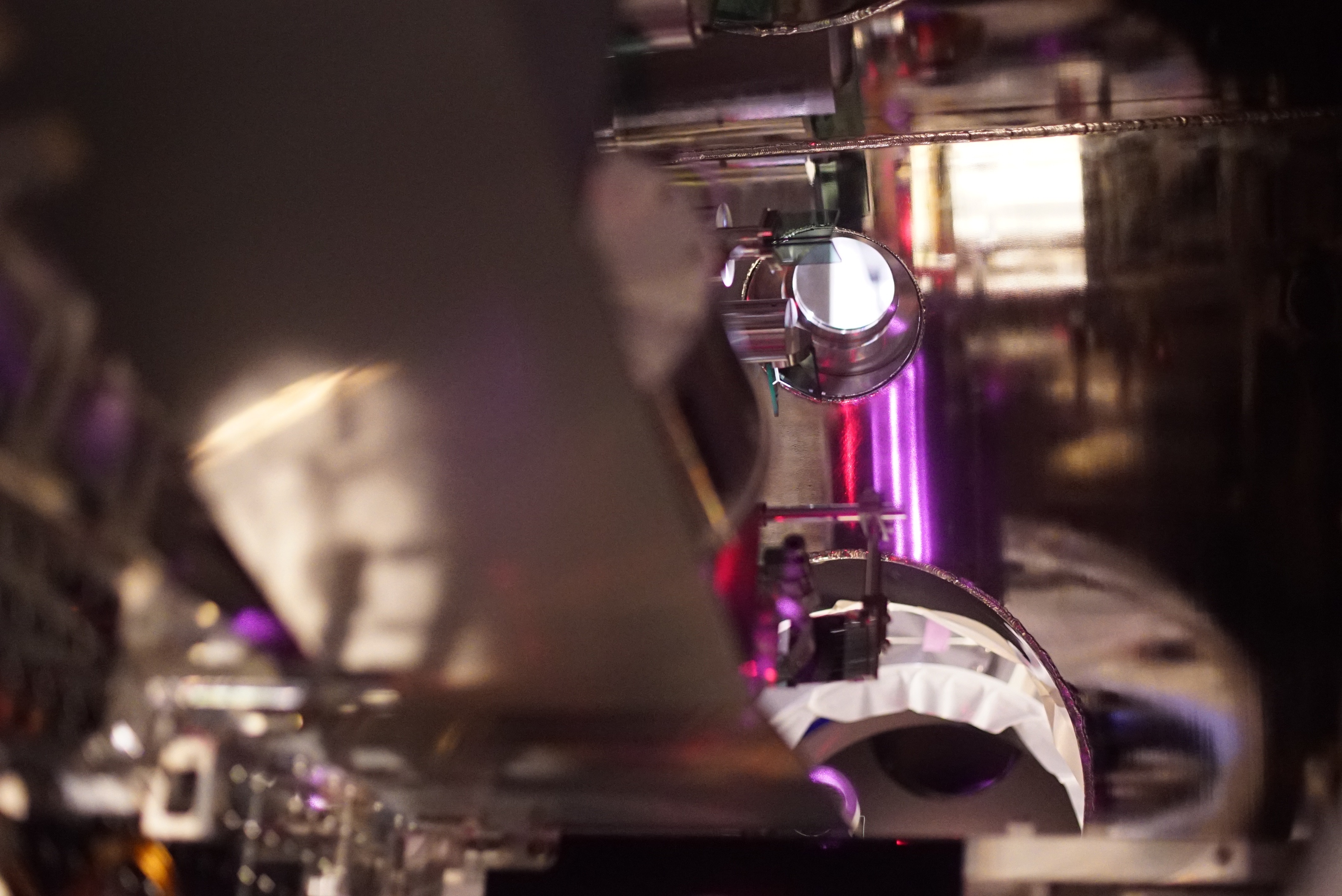
Among these, the first two was not be accessible today. The 3rd one can be seen in Fig. 2, catching two ghost beams and an arch-like scattered light. This photo was taken by Miyakawa-san's IR camera without using a tripod; I holded it with my hands. IR wavelength seems assigned to be shown in violet, interestingly. Unfortunately, there seems stray light field out of the existing dumps; actually, with this IR camera, such faint scattered light fields that have not been seen by sensor cards nor IR viewers, can become clearly seen; so useful. Prepare dozens of this kind of cameras to set everywhere.
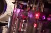
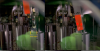
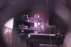
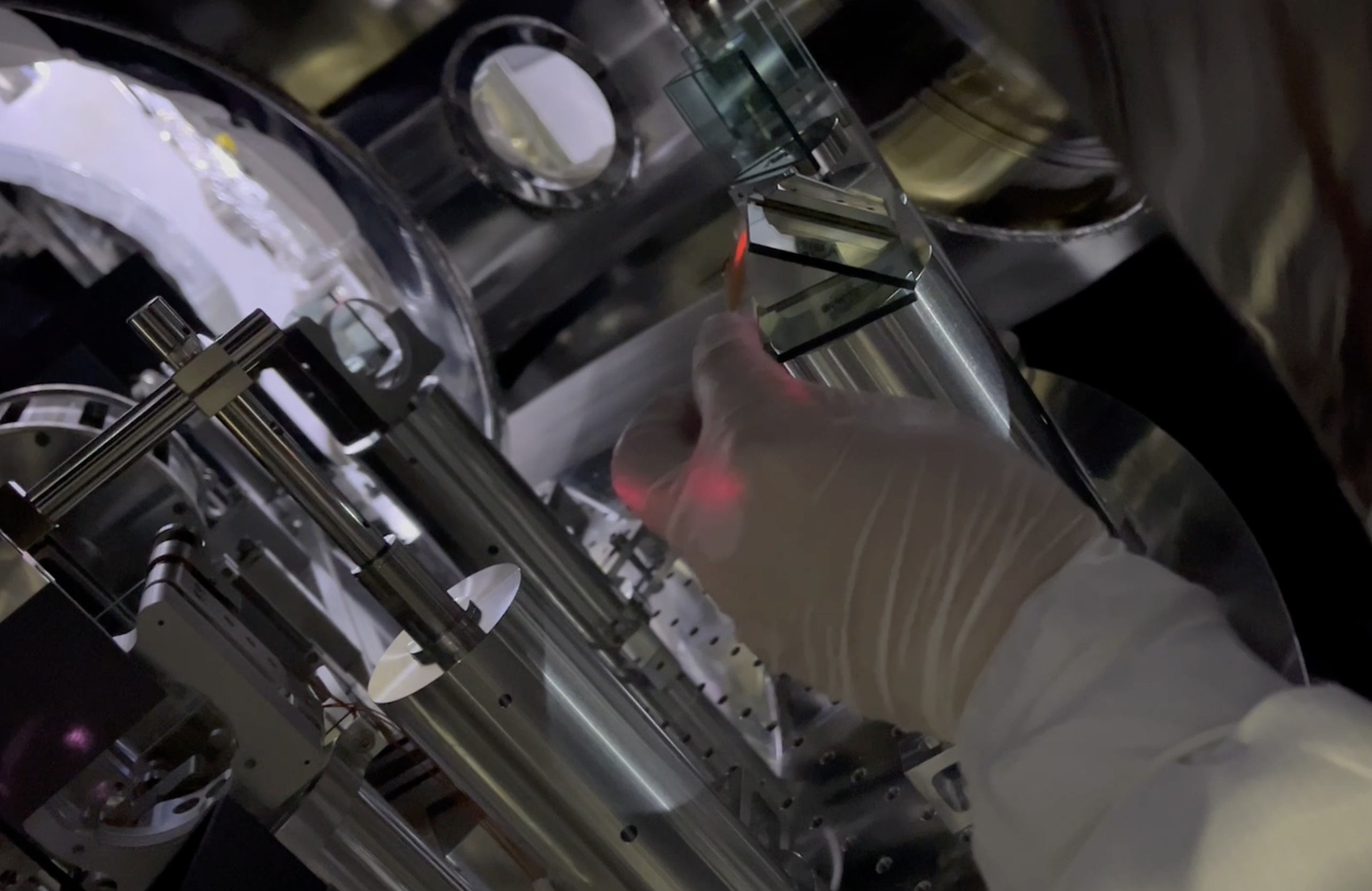
Fig. 3 shows the same scene as of Fig. 2 but taken from different viewpoint. In addition to the already-mentioned stray light, CWP1 seems shining in IR. By the way, in Figs. 2 and 3, the two beam spots on STM1 are due to forward and backward beams. Seemingly they are located not too much close to the mirror holder's edge; good. Fig. 4 shows #14 beam dump still caught a kind of ghost beam.
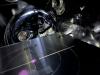
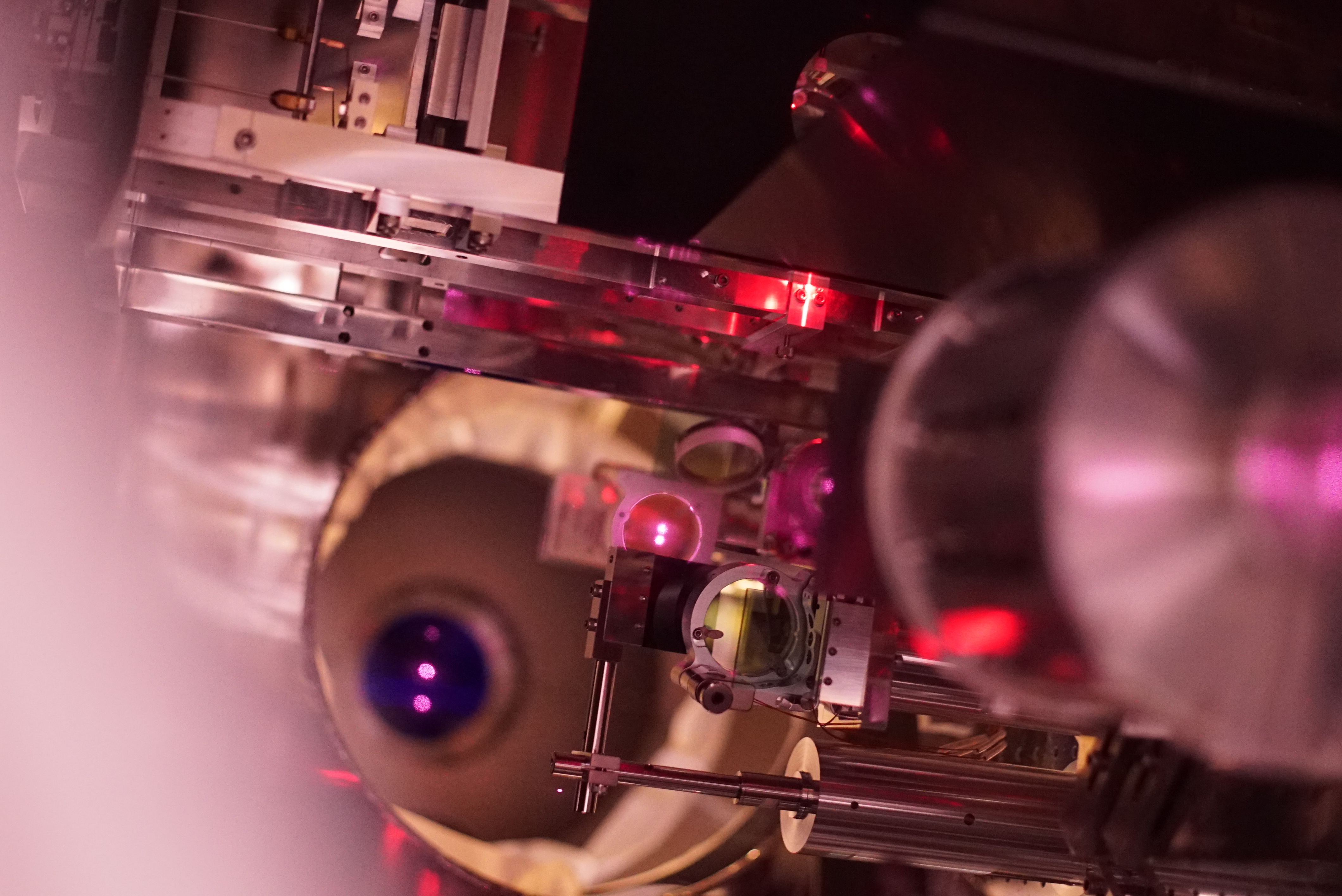
Around STM2
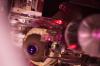
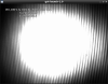
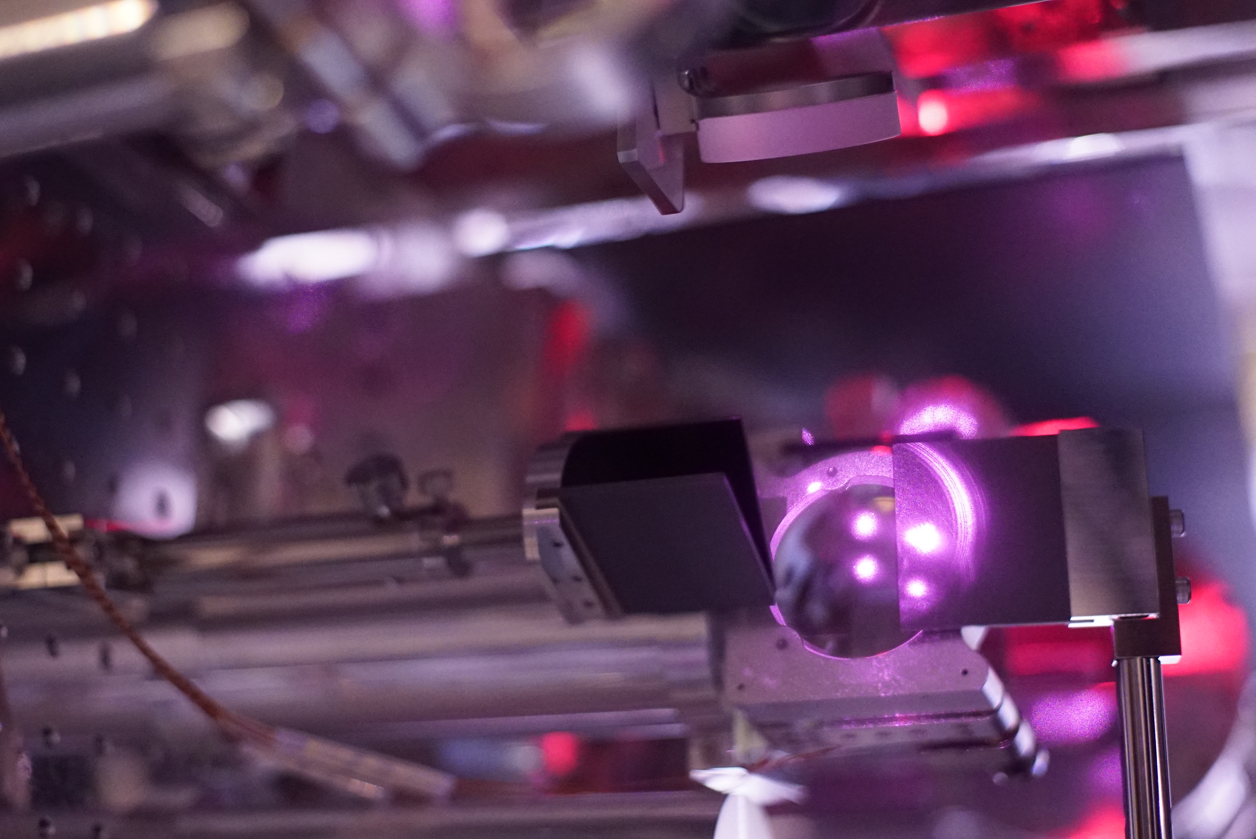
Fig. 5 was taken from behind of STM2. There is a KG5 beam dump behind STM2, and maybe caught transmitting (ghost) beam through STM2. I could not take nice photos to show that the KG5 dump catcing the ghost beams. What would be good would be that the KG5 is not so shining with IR.
Carefully looking at this photo, you can see two spots on STM2, and they should be forward and backward beams. Figs. 6 and 7 was taken from the front of STM2, which is located deep inside the chamber, and the forward and backward beam spots can be clearly seen within the holder edge. Again, there are severe scattered light fields maybe due to IFI (not the chamber's name, but the Faraday isolator itself) can be clearly seen. There might be possiblity that some of the scattered light might be due to a window on GV between MCF and IFI chambers; in Fig. 7, three beam spots can be seen on this window; from the left, these are backward beam to REFL, forward beam from IMC to STM1, and backward beam from PRM. Hopefully some of the scattered field might be mitigated after GV will be opened.
Around IMMT2
There is a KG5 beam dump behind IMMT2. Fig. 8 shows the two ghost beams are within the dump.
Beam dump #13
Fig. 9 is of beam dump #13. As shown in Fig. 1, this ghost beam won't exist if the mirror attached on IMMT2 structure would not exist. This mirror is to take out one of GWP1's ghost beams to out of the IFI chamber for monitoring the input beam alignment before IFI, but never be used at all so far. I personally guess, although making these beam paths took much efforts of us, but this kind of complexity might increase the difficulty of stray light control, so this mirror should be replaced with a beam dump, or making a shroud around IFI.
Beam dump #12
Fig. 10 is of beam dump #12. As shown in Fig. 1, these ghost beams are genereted when the "IFI pick off" beam passing through a viewport window. Again, if we discard the (so far) meaningless plan to use this pick off beam, this beam dump is not needed.
Beam dump #5
Fig. 11 is of beam dump #5, which catches a transmission (ghost) beam of a pick off mirror to reflect the backward beam to REFL table.
Beam dump #11
Fig. 12 is of beam dump #11, which catches two AR reflected (ghost) beams generated at a viewport window through which the backward beam to REFL table passes.
Beam dump #8
Fig. 13 is of beam dump #8; maybe a ghost beam generated at CWP2 by backward beam.
Around input Faraday isolator (IFI)
Figs. 14, 15, and 16 are around the isolator structure. Many ghost beams and/or scattered diffused field are found.
IFI Chamber itself
Fig. 17 shows the inner surface of the IFI chamber seems shining due to stray light field. Regretfully I could not identify from where this came today. Before O5, it may be nice to do
- Detach the unused pick off mirror, and relavant beam dumps to reduce complexity of this chamber.
- Put IFI Shroud
- (Hopefully STM1, 2, and IFI should be suspended...)


Abstract:
GRX and IRX flash were found and X arm can be locked with both IR and GR.
Detail:
1. Alignment of PR3, ITMX, and ETMX:
First, we aligned PR3 so that GRX hit the center of the TMSX GR PD by scaning PR3 alignment.
Then, I scaned ETMX good alignment so that reflection beam was hit on the GR REFL PD (ITMX was MISALIGNED state at that time).
After that, ITMX was scaned so that reflection from ITMX is hit on the GRX REFL PD center.
Then, GRX is flashed, so I ran the script (search_FRX_alignment.py) to find the better alignment of PR3, ITMX, and ETMX.
2. Alignment of PR2:
After alignment of GRX, I tweeked PR2 alignment so that IR reflection from ITMX hit on the REFL PD.
Then, IRX flash can be seen.
After the alignment, PR2 OpLev is cmpletely out of range, so we need PR2 OpLev centering to remember the good PR2 alignment.
3. Lock trial of GRX:
I requested ALS_LOCKED state toXARM guardian and GRX can be locked with TEM00 without any problem.
4. Lock trial of IRX:
I rotated IFO REFL HWP from 176 to 146 degrees to increase the laser power on REFL PD.
Then, I requested IR_LOCKED state to XARM guardian.
Though IR seems resonating, IMC trans power oscilated a lot due to the oscillation of MCL control.
The reason of the oscillation is gain change of MCE actuator, so I added a gain of 0.3 in FM1 (3,500) of LSc:MCL filter bank.
After this modification, IRX can be locked with TEM00 without any problems.
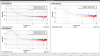
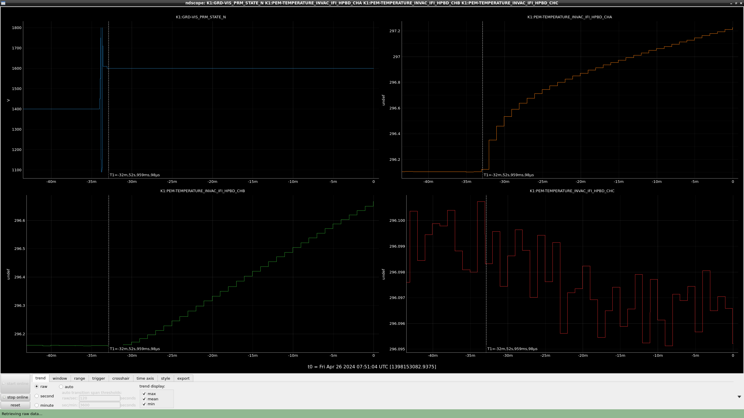
I checked PRM MISALIGNED_BF state, which is used for hitting the PRM reflection beam to the HPBD.
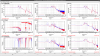
Figure 1 shows the state of PRM and thermometers on HPBD.
T cursor shows the time when PRM reached MISALIGNED for BF state.
After that, HPBD temperature increased gradually, which means the reflection beam hit the HPBD.
I offloaded all GAS filters and IP with the FR.
JGWDoc15750
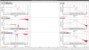
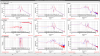
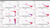
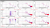
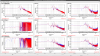
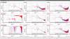
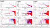
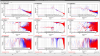
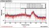
1. The peaks around 30 Hz
The spectrum of geophone has large wide peaks around 30 Hz and the origin was unknown.
But in the spectrum measurement in accelerometer, we cannot detect any 30 Hz peaks.
So I suspect the some unique noise in geophone inside the OMC chamber.
2. The peaks around 225 Hz.
The relatively larger peaks detected in the range of 200-250 Hz in geophone.
Similar peak was detected in the position 1 (+X side of OMC)
There would be some materials which have the resonant frequency at 200 250 Hz.
3. The peak around 125 Hz
The relatively larger peaks detected in the range around 125 Hz in geophone.
The similar peak was detected in position 3,7,8,9,10.
Some origin exist in -X area?
4. Many peaks 150-200 Hz in position 2.
Many peaks around 150-200 Hz in position 2. Beam damper and/or steering mirror?
1. Request OLDAMP_OFF state
2. Touch the TILT/LEN oplev
3. Request LOCK_ACQUISITION state.
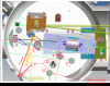
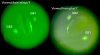
Fig.1. and Fig.2. showed the GigE camera image before and after centering work.

[Yokozawa, Yuzu]
We performed the TCam photo session at 8:06~8:16 this morning. This time, we took only the ITMX image in the Xarm single bounce.
- ITMX Tcam image: [4/1] --> [4/26]
- horizontal shift = -13.2 pixel = -2.2 mm, vertical shift = +6 pixel = 1.0 mm
- The position of oplev light also shifted at the same time. We guessed the steering mirror in the chamber might have tilted, due to the vacuum evacuation(klog#29307)? I will check the ammount of the shift is consistent or not later
Date: 2024/4/26 early morning.
I made the states around "SAFE" of Pcal guardian to be safer.
What I did:
- At "TOSAFE" state:
- The target value of OFS offset values were changed from 0V to 0.01V because the spec sheet of the AOM driver says it should be 0-1 V and I don't know whether a negative value can make trouble.
- Added a block to cut the injection signal. (This is not an essential feature, but makes it safer)
- Added a block to close shutters and open the OFS loops. (This is not an essential feature, but makes it safer)
- At "FAULT" state:
- Added a block to open the OFS loops.
- Adding decorator
- Made a "shutter_check" decorator to monitor the shutters, and this decorator was adapt in SAFE and DOWN states. Because of this modification, if you opened the shutter(s) at SAFE or DOWN state, the guardian would detect it and kick to TOSAFE state to close the shutter(s).
Hirata, Akutsu; following 29308 and 29312.
Summary
Confirmed the locations of PR2 HR mid baffle and PRM AR and HR mid baffles. Reinforced STM2. Confirmed that the reflected beam from IMMT2 was far from high power beam dump. Confirmed that the beam from PRM was passing far from PR3 (so the open angle of PRM-PR2-PR3 beam seems 0.02 rad).
Setup
- IMMT1 and 2: ALIGNED state; IMMT2 sometimes went to ALIGNING.
- PRM ALIGNED state; depending on the situation, PAY_FLOAT was called; sometimes, wishing rigorously fix the angle of the mirror, LOCK_ACQUISITION was called.
- PR2: mainly PAY_FLOAT
- IO Guardian: PROVIDING_STABLE_LIGHT, and also HOLD_ALIGNMENT to IMC Guardian additionally.
PR2 HR mid baffle
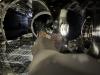
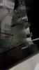
As was confirmed in 29312, we started with checking the beam position at PR2 HR mid baffle aperture, and seemed the spot was 3.5 mm in plus Y direction with respect to the aperture (Fig. 1), as already reported.
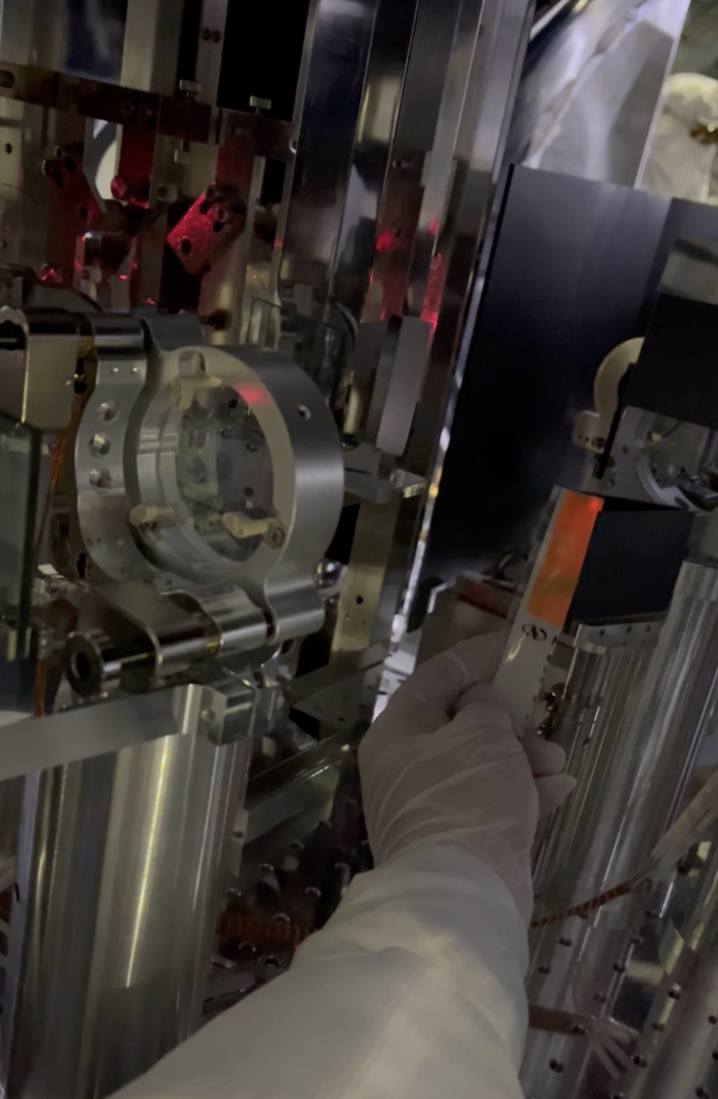
PRM mid baffles
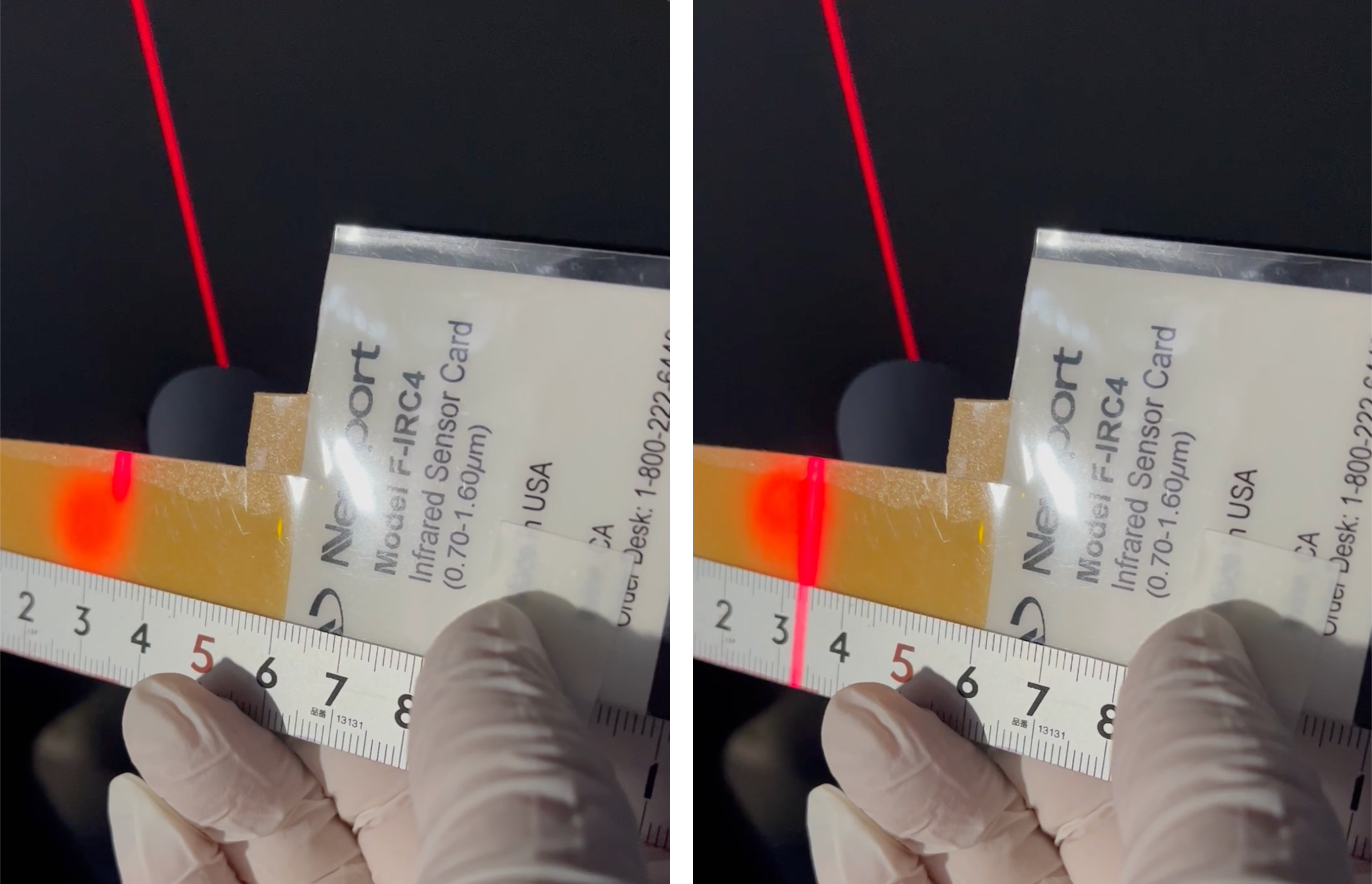
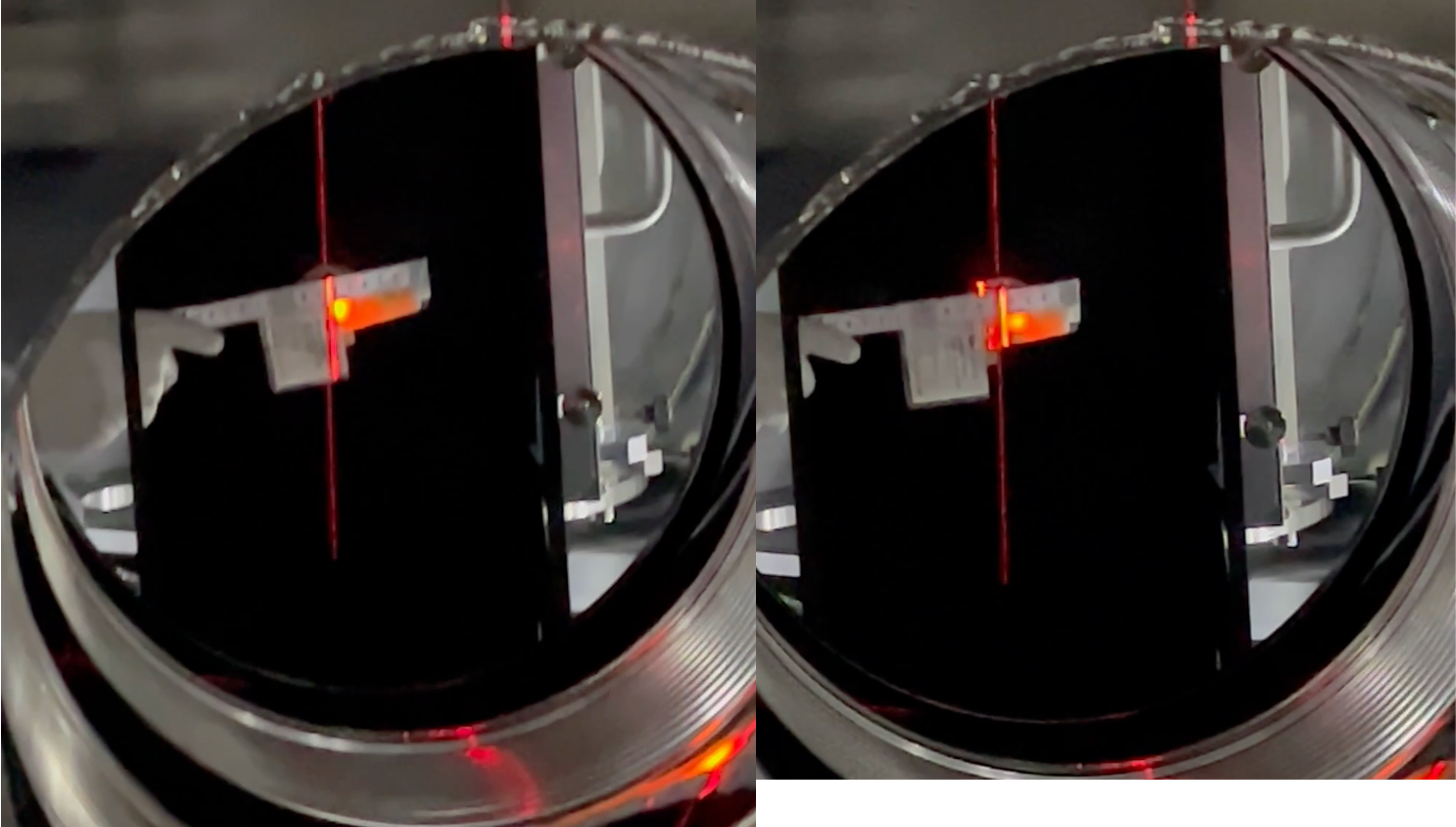
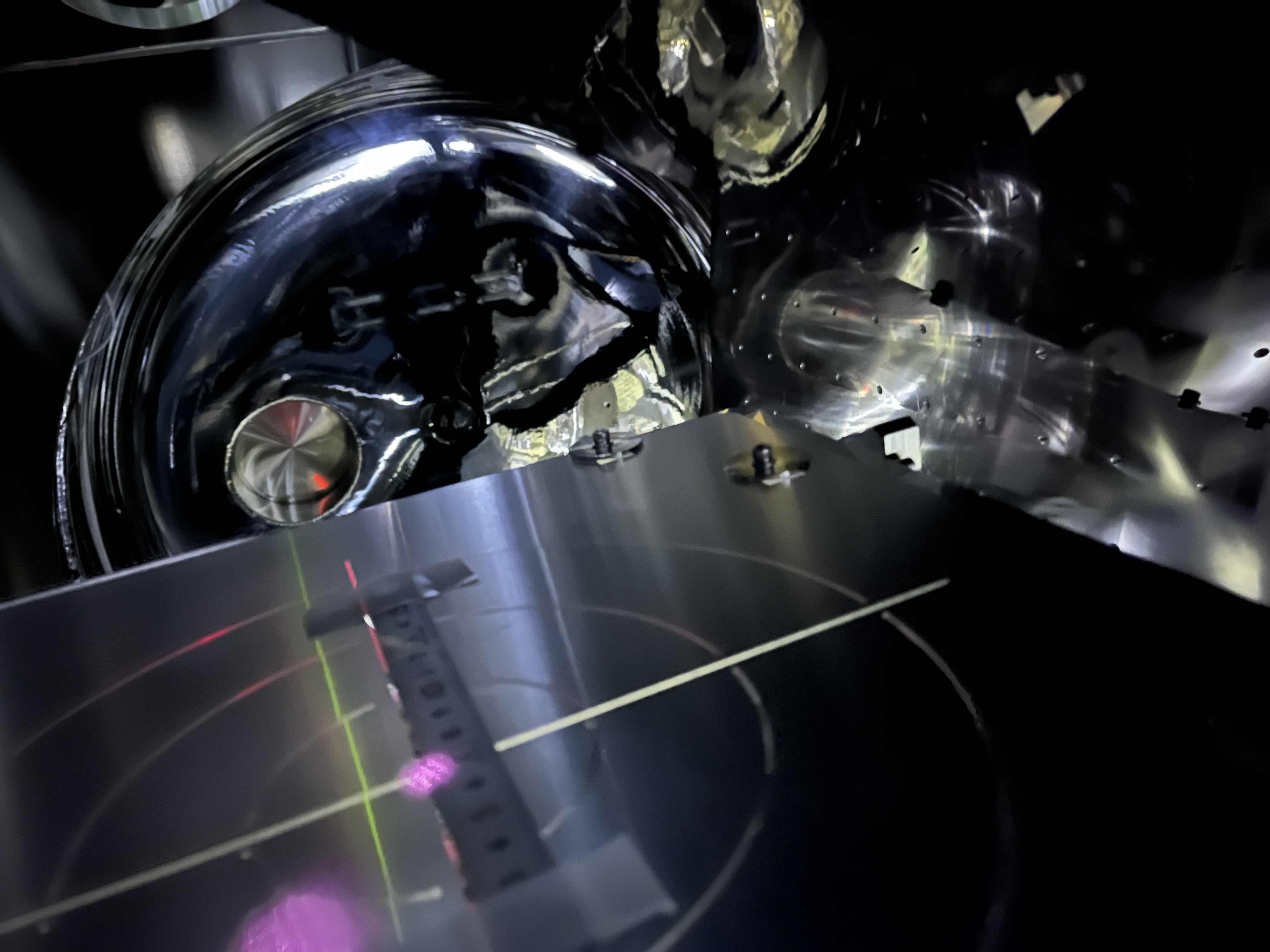
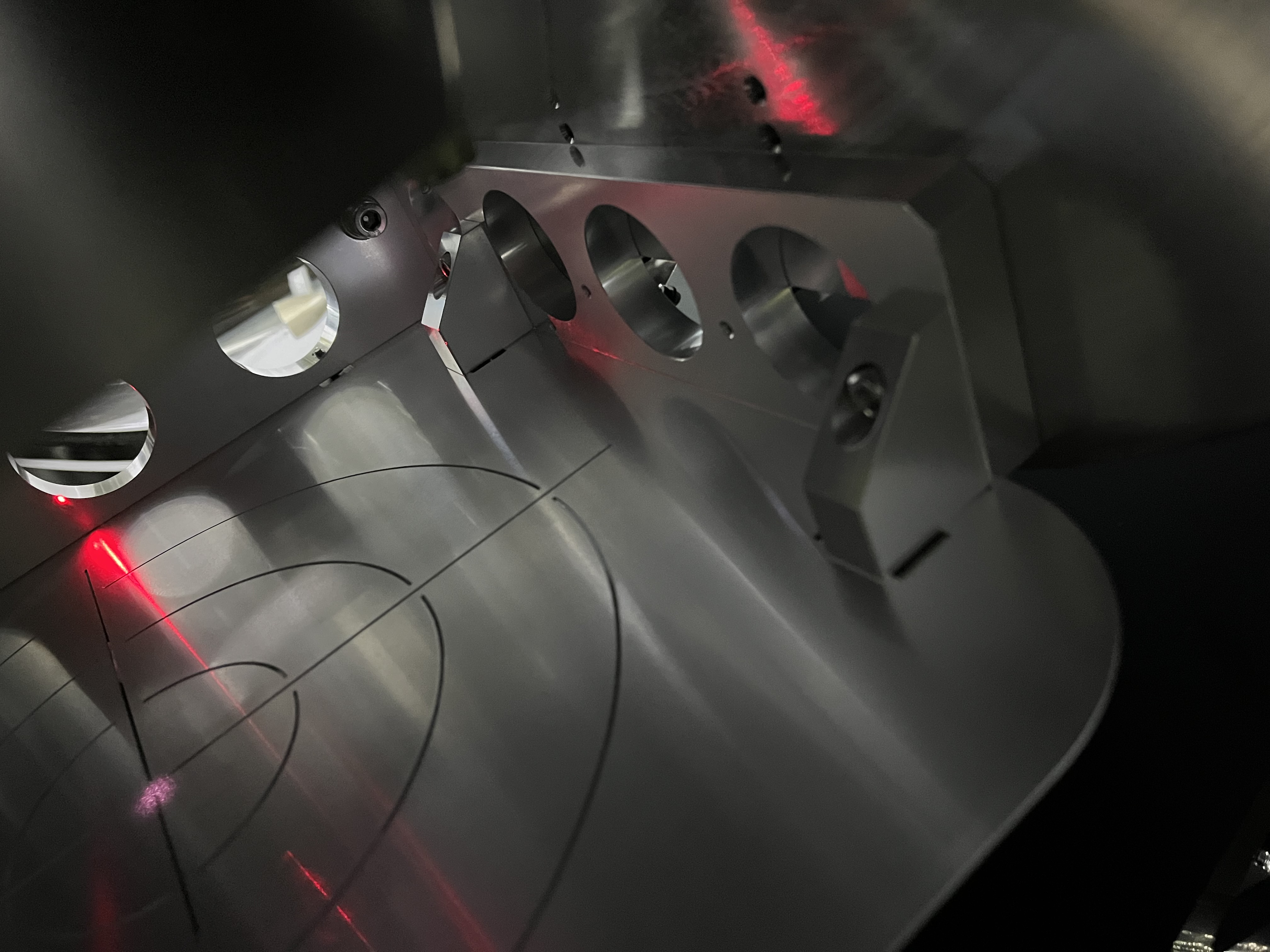
It is difficult to confirm the relative postion of the beam spot at PRM mid baffles due to severe accessibility. We tried several ways (see Fig. 2 and 3, for example; they are respectively of PRM AR and HR side; taken by Miyakawa camera on a tripod; maybe due perspetive, it would be hard to say how much the aperture is dislocated with this way). In the end, using the same method as reported in 29282, we were able to "draw" a vertical line to show the center of PRM AR mid baffle aperture. Then inserting a sensor card with a ruler, we maybe able to say that the beam spot would be ~ 5 mm off-centered in the minus Y direction from this line (Fig. 4), while the noimal number should be 6 mm (JGW-T2214066-v1). So we satisfied at this point.
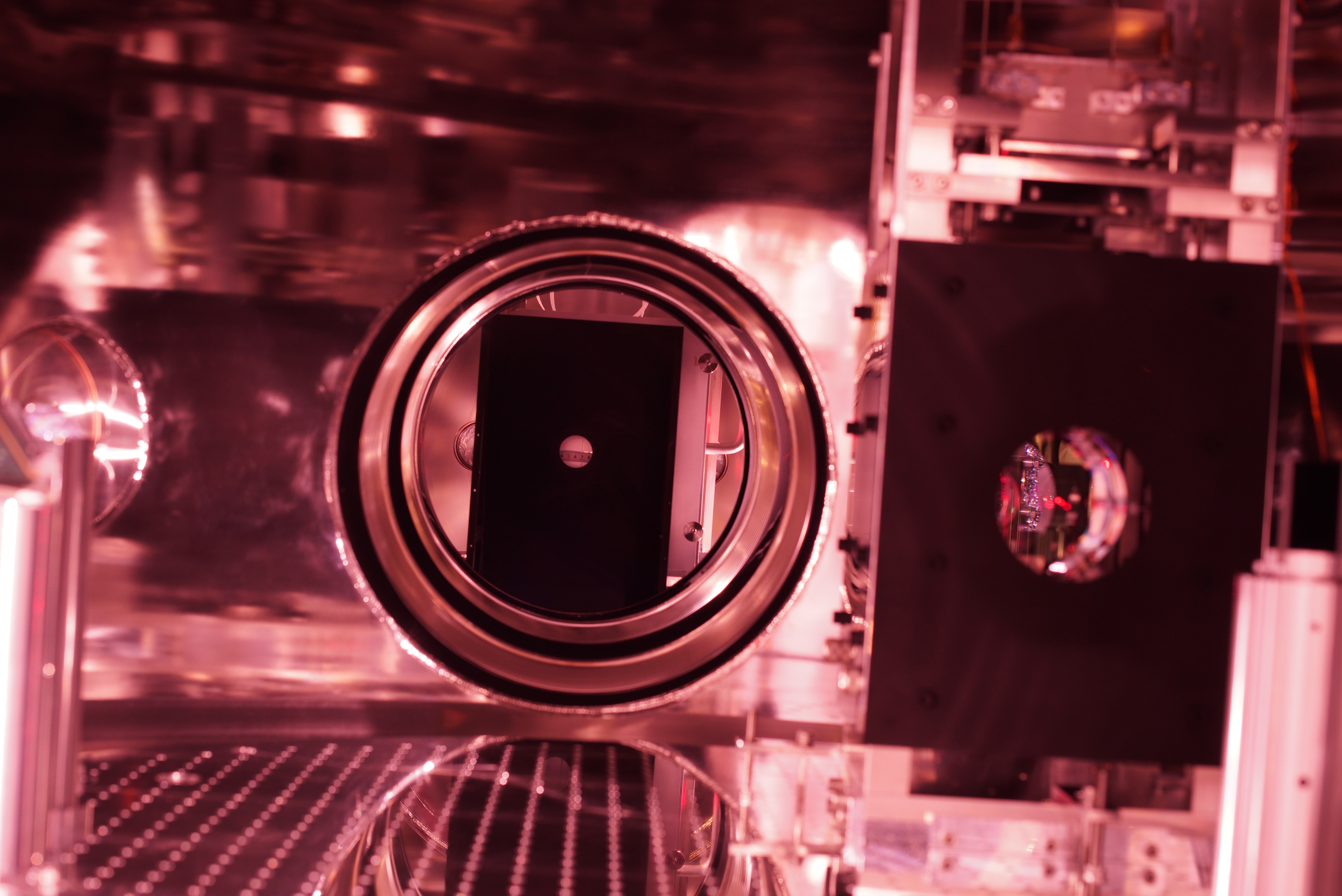
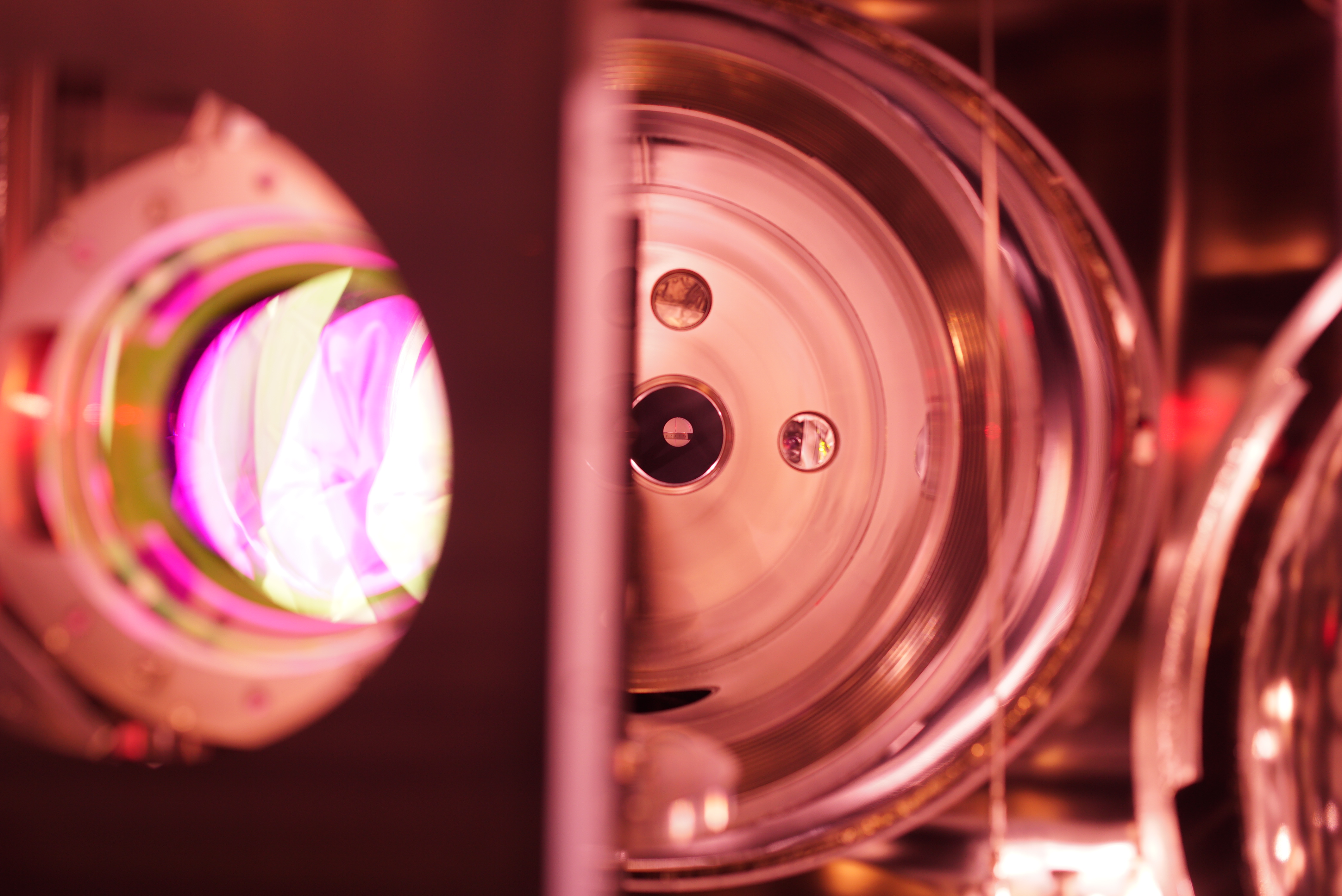
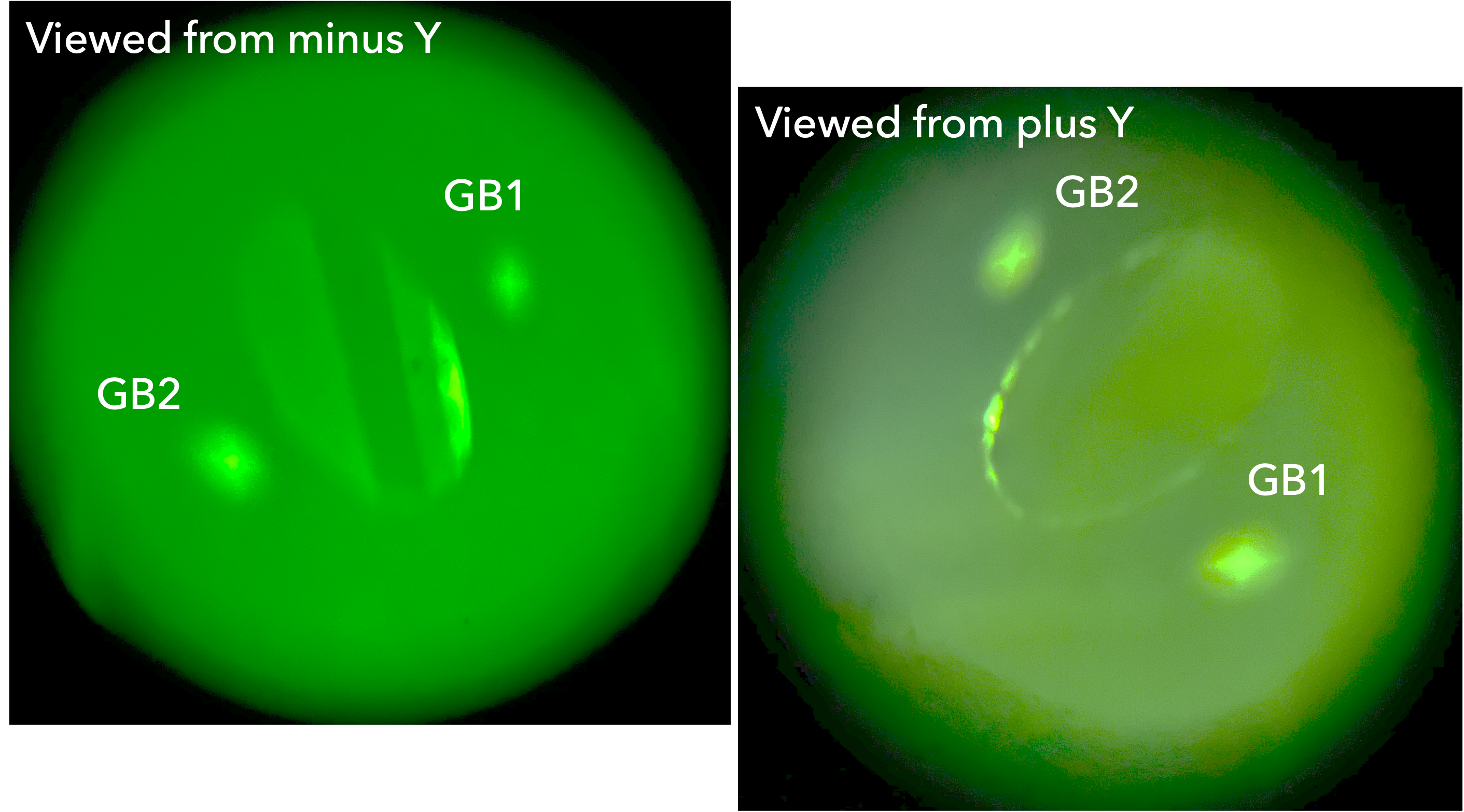
By the way, Fig. 5 is the beam spot on PRM AR target, while Fig. 6 for PRM HR target. As seen, on PRM AR target, the beam spot was mostly centered; on PRM HR target, maybe due to the refraction, the beam spot was a few mm (2.5 mm? see JGW-D2012020-v2) off-centered in the plus Y direction.
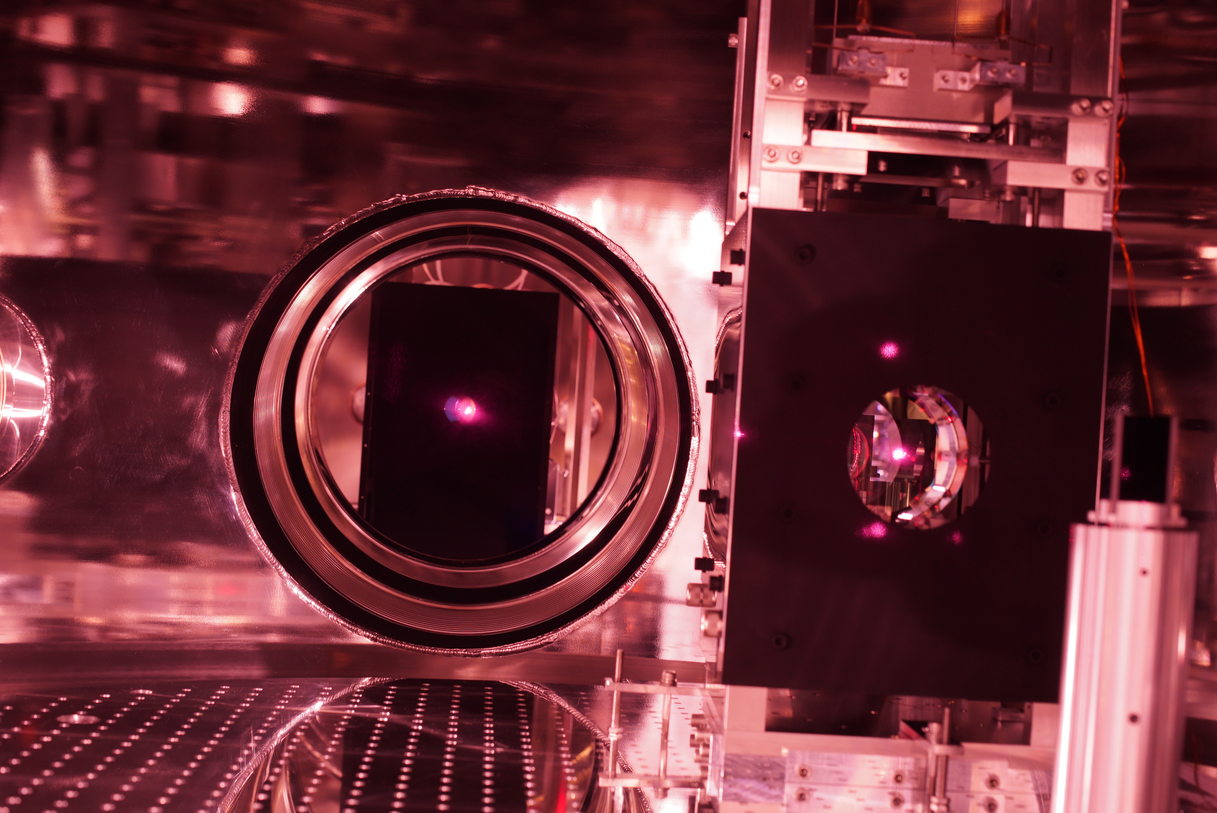
At the same time, ghost beams from PRM on PRM AR mid baffle were checked (Fig. 7). The nominal locations are found in JGW-T2214066-v1, and qualitatively no inconsistency. Also, Fig. 8 was taken from IFI-IMM by Miyakawa IR camera; as seen, "both" side of the aperture edge of PRM AR mid baffle seemed equally shining. The small beam spot left of the main beam spot on PRM would be of surface scatter due to the ghost beam (main incindent -> PRM HR -> -refleceted to AR -> reflected to HR -> exit from AR). When this photo was taken, the camera was set in between the optical beams of IMMT1-to-IMMT2 and IMMT2-to-PRM somehow. The camera hight was somehow set at about the same as those beams. The perspective view seemingly be similar to those in 3D CAD somehow, but it would be difficult to say something definit. At least, qualitatively no inconsistency tendency as follows found; the beam spot on PRM seems left-ward; in the AR baffle aperture, the HR baffle apperture edge could be seen like a crescent...
By the way, in Fig. 8, on the IMMT1 shield, three or four apparent ghost beam spots are seemingly distributed, other than the IMMT1 spot itself. In my observation they are all due to PRM main reflection; When PRM Guadian was at PAY_FLOAT, they were dancing, and stopped when ALIGNED or LOCK_ACQUISITION. My estimation senario is that the PRM backward beam is reflected within IFI, which is made of several optics, and each ghost beam would be reached the IMMT1 shield somehow. One can also see a ghost beam spot in the beam dump in front of IMMT1; this SiC one catches a ghost beam from IFI.
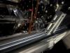
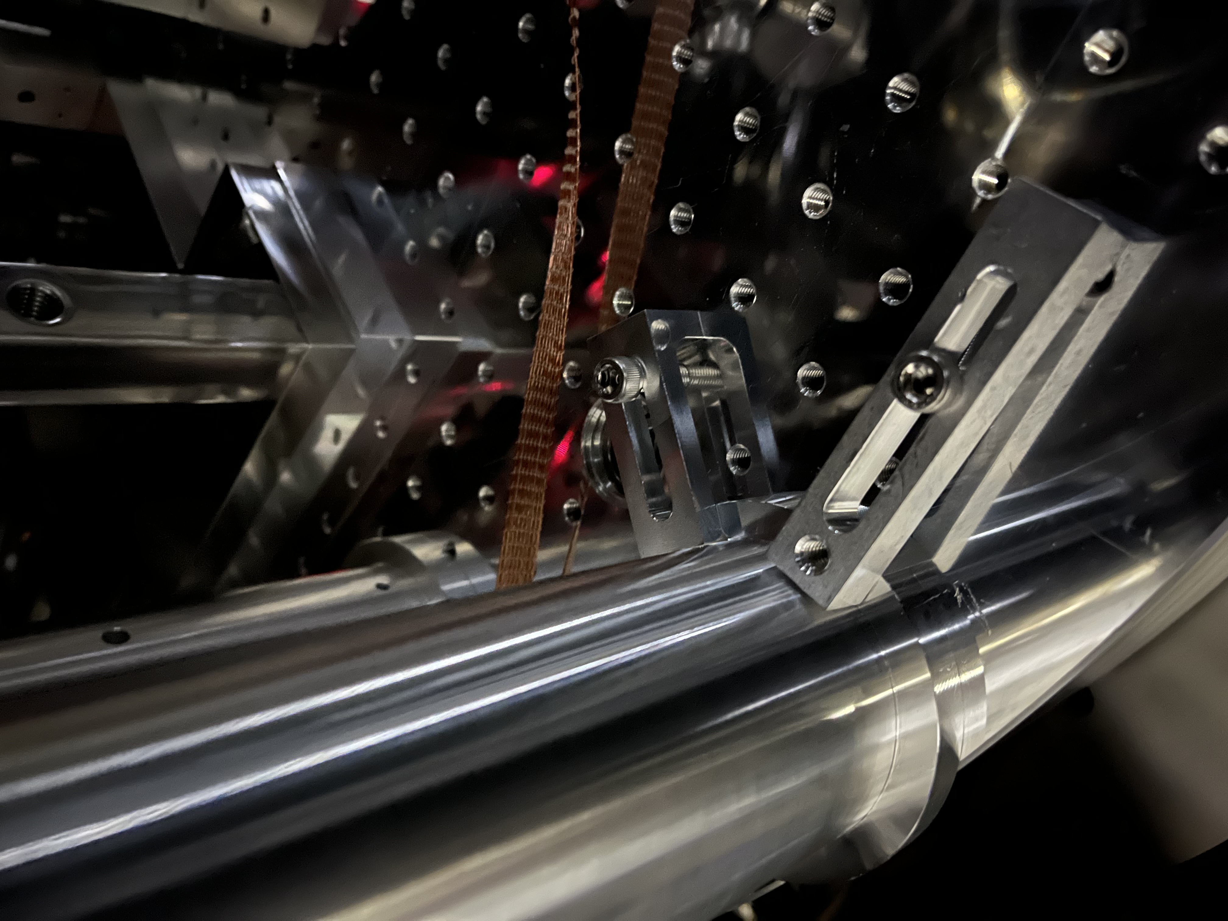
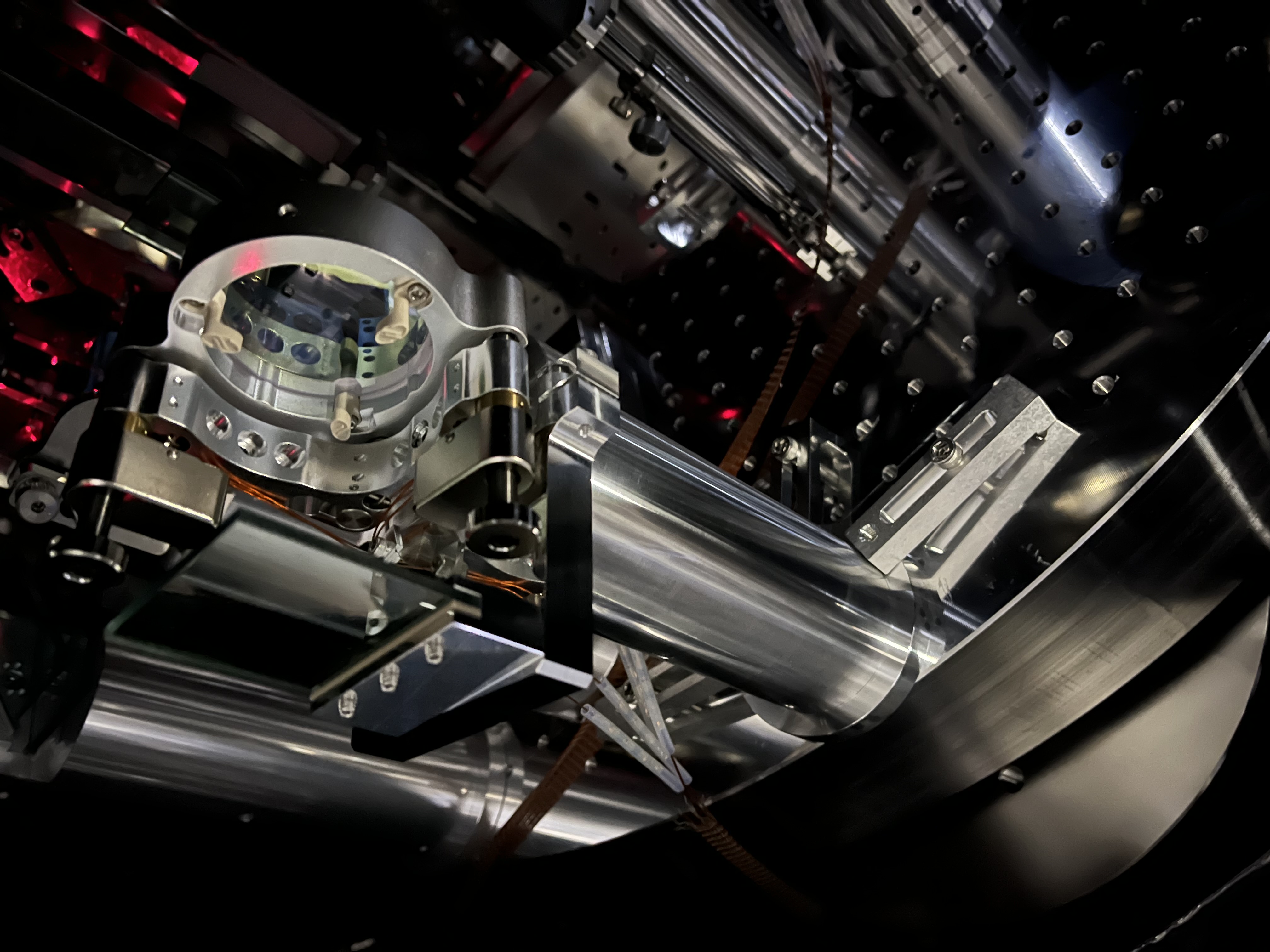
STM2 reinforcement
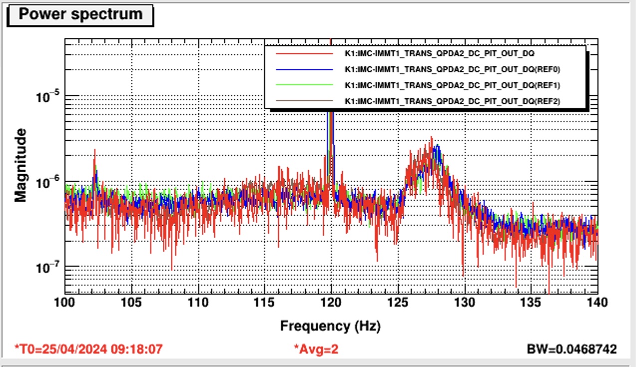
We set another clamp for the pedestal of STM2 (Figs. 9 and 10; the CL-5 type aluminum one in the deeper inside on the table)while carefully looking at IMMT1T QPDs and POP_FORWARD QPDs; this is related to 24703 (ref: 24697 as well, althogh the main topic of this post was not this bump, but some characteristic was mentioned here). Before and after this work, I checked K1:IMC-IMMT1_TRANS_QPDA2_DC_PIT_DQ spectra, but basically no change around 120-130 Hz area; there was a bump (Fig. 11; blue and green are some reference; red is under experiment; the bump slightly shifted after my works/experiments). What I found was that when I only slightly touch a thick cable for picomotors for STM2, this spectum sensitively responded (it was hard to distingush the response whether I would mere shut the optical beam occasionally by my body or not, though...). I checked if this bump would disappear or not by tentatively fixing this cable with white tapes somehow, but not big changes observed. Anyway, the sensitivity seemingly larger than the other point in the IFI chamber I guess.
Please do some cross-check, and hopefully some treatment should be done before closing this area. Currently, maybe most of the frequency band is dominated by acoustic disturbance, so the next time you should make a tube to connect IFI and IMM chambers to avoid this disturbance.
Light beam position near high power beam dump
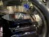
As already reported in 29308, The light beam reflected at IMMT2 was passing through far off high power beam dump so no clip should happen (Fig. 12).
Light beam position near PR3
The light beam thourgh PRM was passing through far off PR3's recoil mass (Fig. 13). From this, the open angle of the light beams connecting PRM-PR2-PR3 should be not 0.013 rad, but should be close to the nominal designed value, 0.02 rad; PR2-PR3 distance is about 11 m (see wiki), so 0.02 rad open angle means the beam separation must be 0.02*11 = 220 mm or so, which would be consistent with this photo somehow.
Note
A strange thing; according to JGW-T2214066-v1, the PRM AR and HR mid baffle should be displaced about 9.3 mm nominally; the HR one should be shifted in the minus Y direction. But today we found that there was only ~3 mm displacement. Where 6 mm gap went..? Is Fig. 3 (the center of the target seemd offcententered to the aperture, but I cannot discard this is due to perspective or parallax) related to this issue? Actually the beam spot on this target is a few mm in the plus Y direction according to Fig. 6, but may not be 6 mm. At any rate, 6 mm shifting would be too much. That's why we did not touch both sides of PRM mid baffles.


Ushiba, Hirata, Akutsu
Summary
Reduction of LO for PMC locking, which might be similar but not identical (?) found in the past (19472), happened. This LO power was manually (kind of) recovered, but I have no idea how we could avoid this happening again.
Details
During works 29334, IMC or even PMC suddenly became unable to be locked. In my view, this happened when I requested PROVIDING_STABLE_LIGHT to IO Guadian from PSL_LOCKED. Anyway, Ushiba-kun pointed out that LO level was under the threshold (maybe set at 19472). We were not sure what the "LO monitor" channel meant, but I found that the LO signal generator in the PSL room displayed 8.1 dBm while its nominal power should be 8.6 dBm according to a label attached on its body. I tweaked a knob on the signal generator to tweak the displayed output power to 8.6 dBm, but Ushiba-kun said that the "LO monitor" signal was still slightly under the threshold, so I tweaked it to 8.7 dBm, then PSL and IMC lock came back.
I have no idea why and how this happened. Looking at the "LO monitor" to the past, actually recently sudden reduction of the output power were sometimes observed. So this might repeat again.
One hint might be that I saw a kind of "unstable" state changing in IO Guadtian when I requested PSL_LOCKED when I finished works before lunch (but aruond 13:30). What I did before this was just requesting PROVIDING_STABLE_LIGHT to IO Guardian, and then requested HOLD_ALIGNMENT.
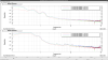
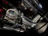
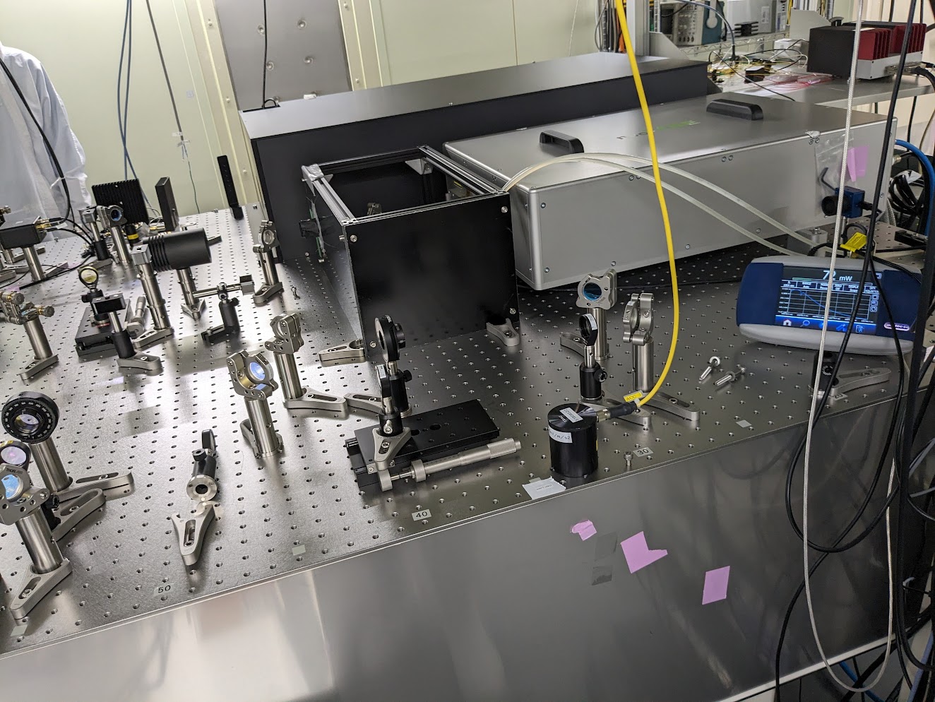
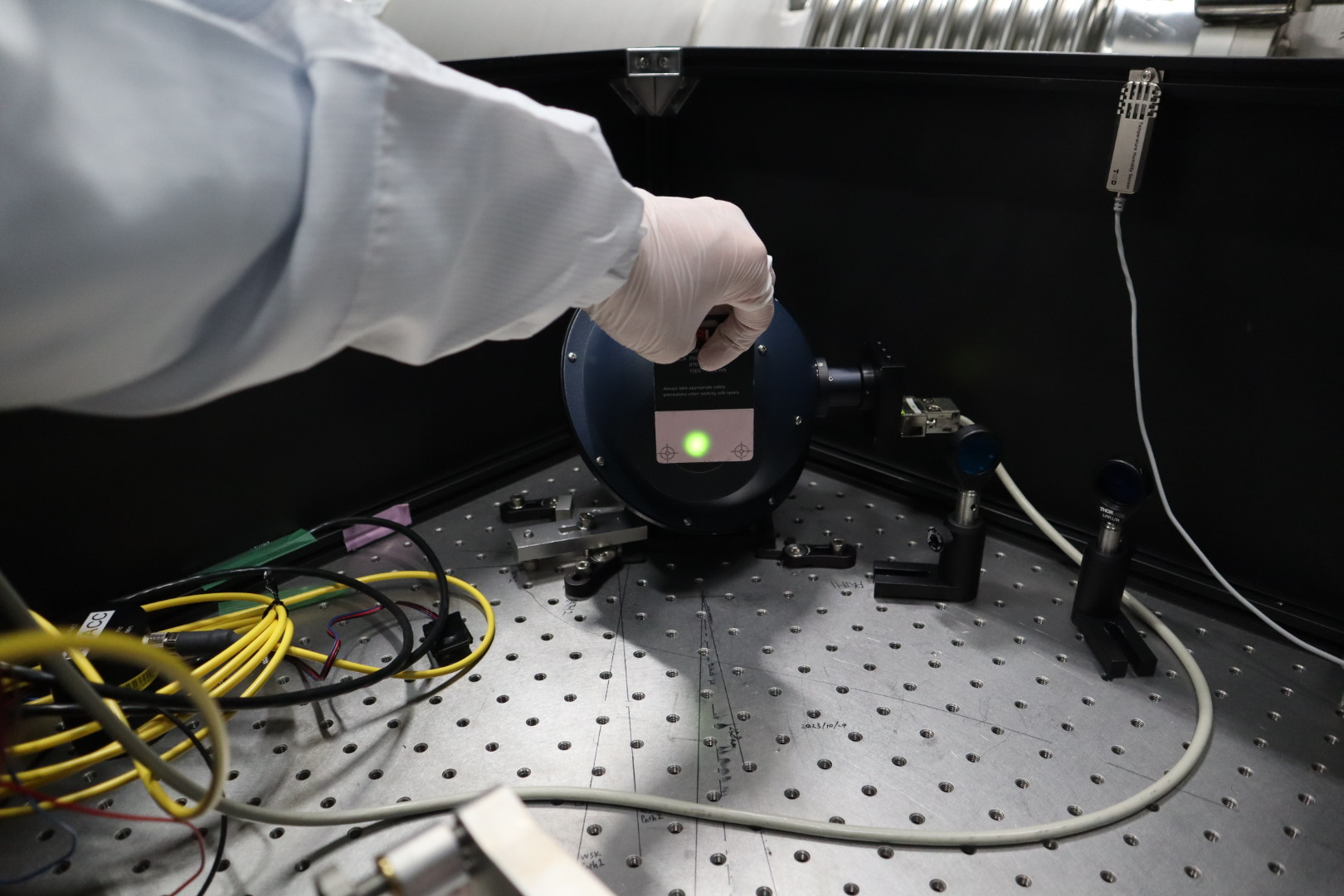
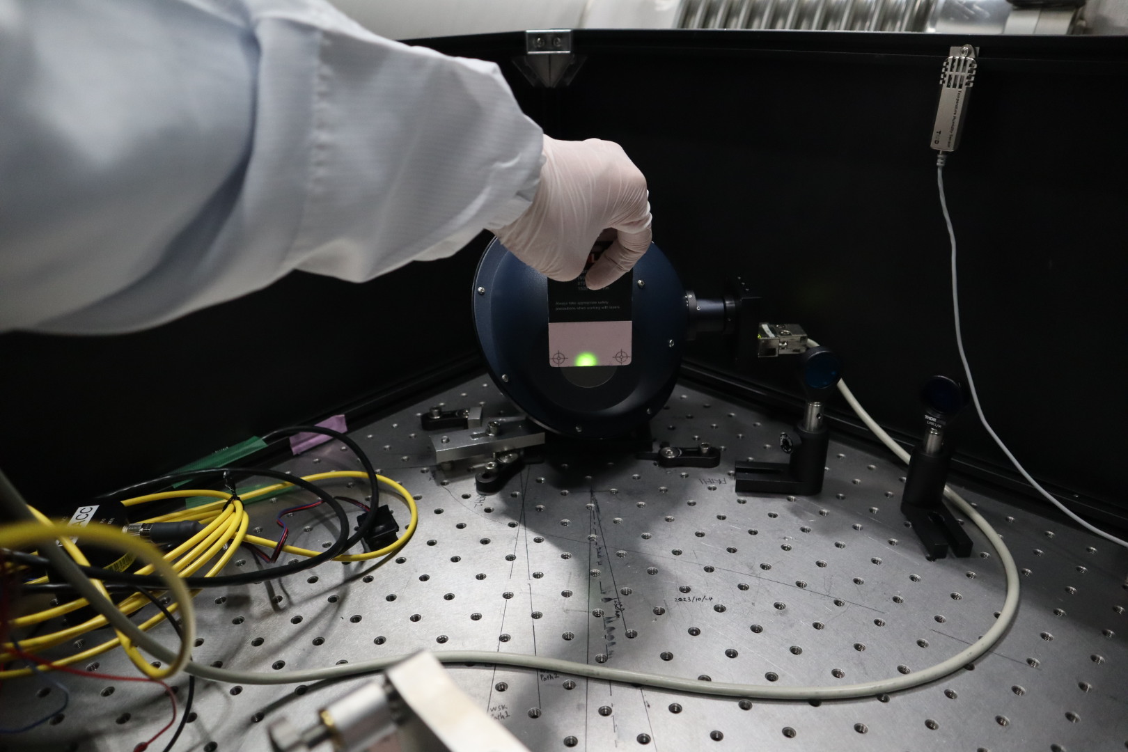
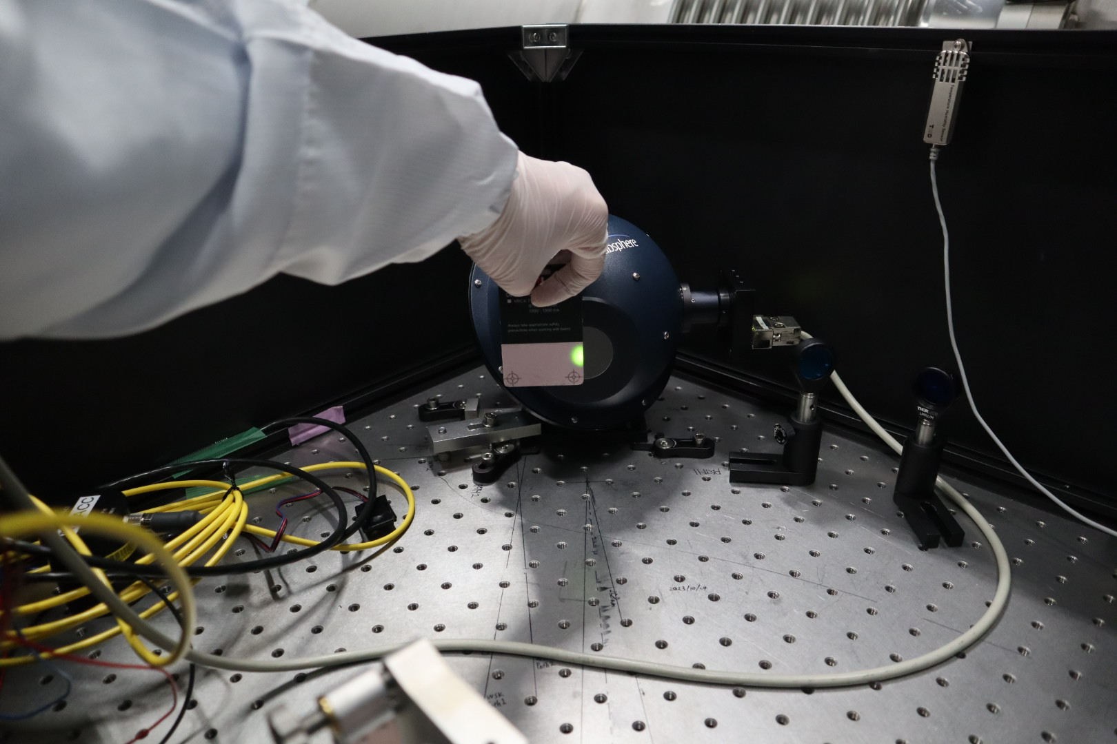
-We aligned the seed laser to the solid amplifier to maximize the output power.
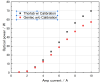
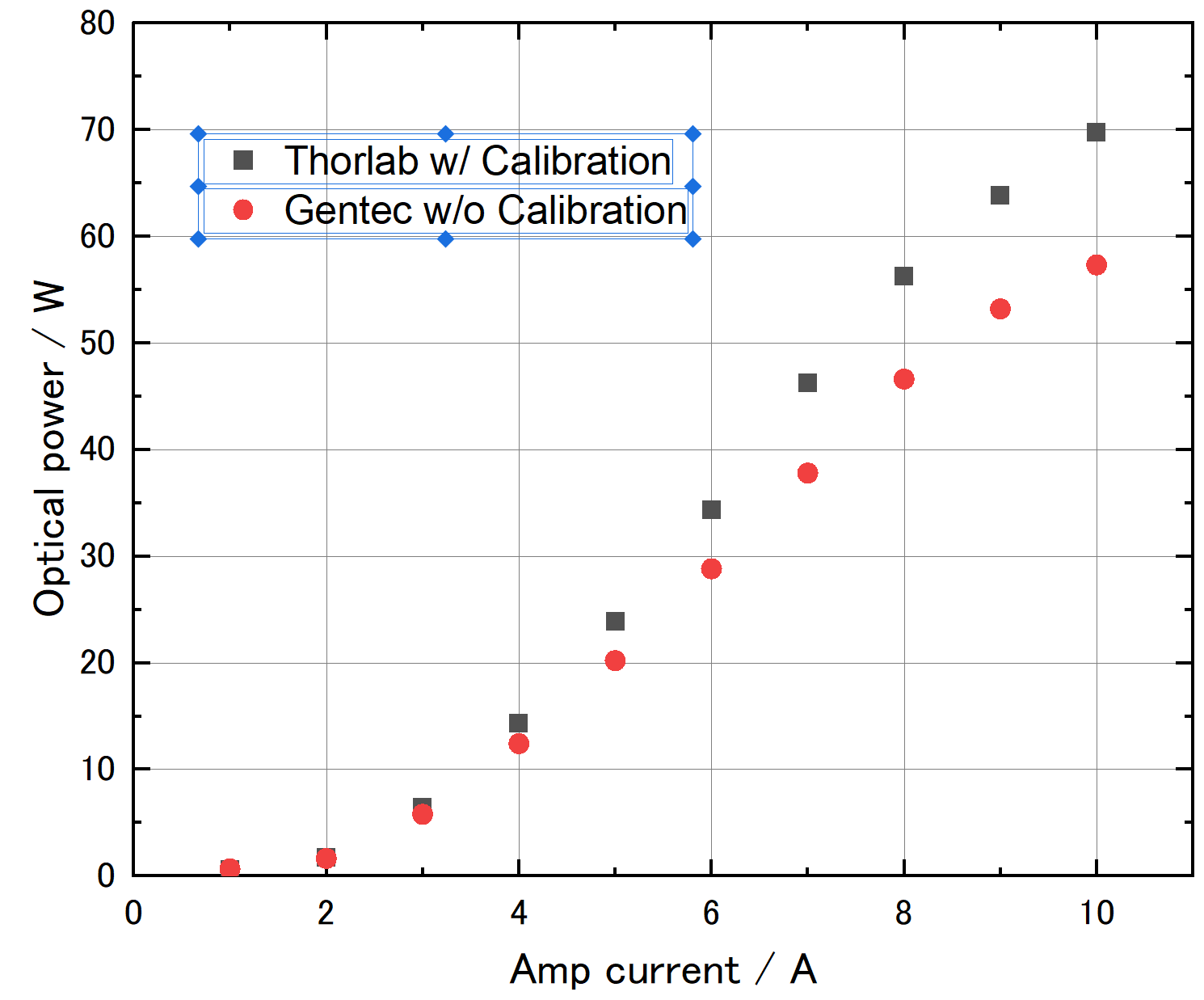
-After the alighnment, we measured the laser light power against the injection current of the optical amplifier using a Thorlab power meter (calibrated) and a Gentec power meter (not calibrated). Attached figure (laser_IP-chara.png) is the characteristics. The laser power measured by Thorlabs is 1.22 times higher than Gentec's.
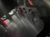
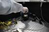
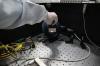
-We set a box (box.jpg) for beam profile measurements later.
With Hido Shingo
We performed the fine adjustment for the Pcal-X alignment with the ALIGNED state of the ETMX suspension.
We used PCAL_EX1(in Tx module) and PCAL_EX2(in EXA chamber) picomotors to adjust the path 1 so that the paths passed through the design position on the ETM and the center of the RxPD.
We left the Pcal-X laser ON, and the Pcal-X guardian state at OFS_CLOSED_LOW_POWER.
Attached files are showing beam positions on ETM and RxPD.
The total picomotor steps we requested are:
- PCAL_EX1, pico 2 (path 1 yaw): -550
- PCAL_EX2, pico 1(path 1 yaw): -600
- PCAL_EX2, pico 2(path 1 pitch): +400
- PCAL_EX2, pico 3(path 2 yaw): +100
- PCAL_EX2, pico 4(path 2 pitch): +300
The final optical efficiencies were (quick measurement):
- Path 1: 97.0%
- Path 2: 96.5%
- Path 1+2: 96.7%
These are similar to klog28820.
By analyzing the recent TCam images, I identified the mirror center of ETMX, ITMX, and ITMY. When the ETMY or GreenY is ready, we will try to take the ETMY image and identify the mirror center.
Details
- For ETMX, I had an accidental chance to take the TCam for ETMX illuminated by Greenx on 4/23 (during adjustment work of PR2). For ITMX and ITMY, the image was taken on 3/15 (klog#28863).
- Note that the ETMX image was taken after the evacuation an the ITMX and ITMY images were taken before the evacuation.
- ETMX
- fitting result
- overlay with previous reference center (Magenta shows the previous mirror edge and center. Yesllow shows the latest fitting result)
- From this analysis, I updated the fixed radiuss of 1243 pixel which was computed from the conversion factor of 10/113 = 0.0885 [mm/pixel]. This was evaluated from the metal-scale-insert test(klog#28843).
- ITMX
- fitting result
- overlay with previous reference center (Magenta shows the previous mirror edge and center. Yesllow shows the latest fitting result)
- From the metal-scale-insert test(klog#28843), I evaluated the conversion factor as 10/60 = 0.167 [mm/pixel]. Accordingly, the mirror radius could be 660 pixel. But, this estimation has large uncertainty. If one pixel changes in the estimation, the mirror radius changes 600~733 pixel. I decided to use the fixed radius of 630 pixel which we evaluated by hand fitting with Aogaku members previously, because this value has the small uncertainty than the metal-scale-insert test.
- ITMX
- fitting result
- overlay with previous reference center (Magenta shows the previous mirror edge and center. Yesllow shows the latest fitting result)
[Kimura and M. Takahashi]
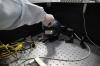
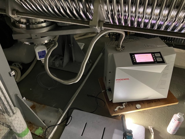
To identify the source of the liquid material that entered the EYA tank, three filters of the air compressor and the inside of the connection piping of the dry pumps for vacuum pumping were visually inspected.
As a result of the visual inspection, no traces of liquid material were found inside the filters of the air compressor and the connecting piping of the dry pumps for vacuum pumping.
The smell inside the filter and piping was confirmed by nose, but the same irritating smell observed in the EYA tank was not found.
Three filters of the air compressor were replaced with new ones because more than two years had passed since the last replacement.
I have already made segments that excludes the IPC error segments from the science mode.
/home/detchar/Segments/K1-GRD_SCIENCE_MODE_NO_IPC_ERROR
[Kimura and Ueda (SKS) ]
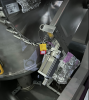
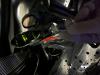
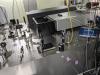
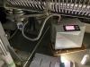
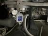
On the afternoon of 18 Apr., Ueda-san and me performed a vacuum leak test for new pressure gage of GVetmx.
The results of the vacuum leak test confirmed that the new pressure gage of GVetmx did not leak more than 1x10^-12 Pam^3/s.
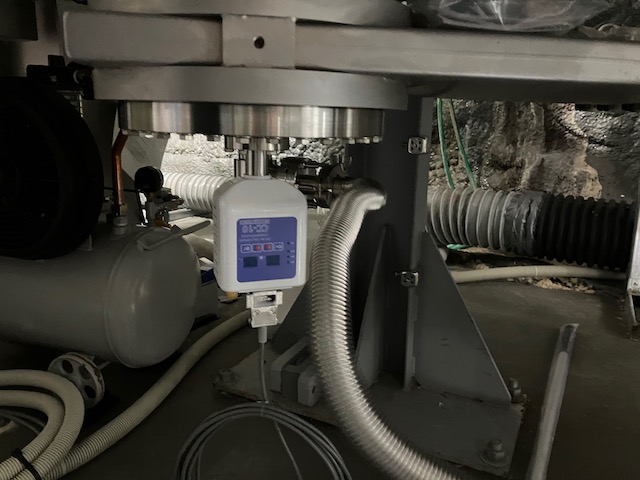
[Kimura, and M. Takahasshi]
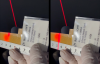
On the morning of 25 Apr., M. Takahashi-san and me performed a vacuum leak test for new pressure gage of GVetmy.
(See attached photos 1~2)
The results of the vacuum leak test confirmed that the new pressure gage of GVetmy did not leak more than 1x10^-12 Pam^3/s.
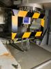
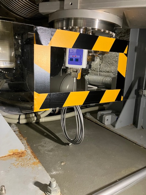
After the leak test, we set up protection panel in front of the gage.
(See attached photo 3)
The protection panel for the gage of GVetmx was set up, too.
![[4/1]](https://gwdet.icrr.u-tokyo.ac.jp/~controls/capture/tcam/ITMX_fit/2024/0401/TCam_ITMX_00111_2024_0401_174704_fit.png)
![[4/26]](https://gwdet.icrr.u-tokyo.ac.jp/~controls/capture/tcam/ITMX_fit/2024/0426/TCam_ITMX_00011_2024_0426_081020_fit.png)
Uchiyama
I turned on 4 TMPs to pump down IXC at around 9:45.