Hirata, Akutsu; following 29308 and 29312.
Summary
Confirmed the locations of PR2 HR mid baffle and PRM AR and HR mid baffles. Reinforced STM2. Confirmed that the reflected beam from IMMT2 was far from high power beam dump. Confirmed that the beam from PRM was passing far from PR3 (so the open angle of PRM-PR2-PR3 beam seems 0.02 rad).
Setup
- IMMT1 and 2: ALIGNED state; IMMT2 sometimes went to ALIGNING.
- PRM ALIGNED state; depending on the situation, PAY_FLOAT was called; sometimes, wishing rigorously fix the angle of the mirror, LOCK_ACQUISITION was called.
- PR2: mainly PAY_FLOAT
- IO Guardian: PROVIDING_STABLE_LIGHT, and also HOLD_ALIGNMENT to IMC Guardian additionally.
PR2 HR mid baffle
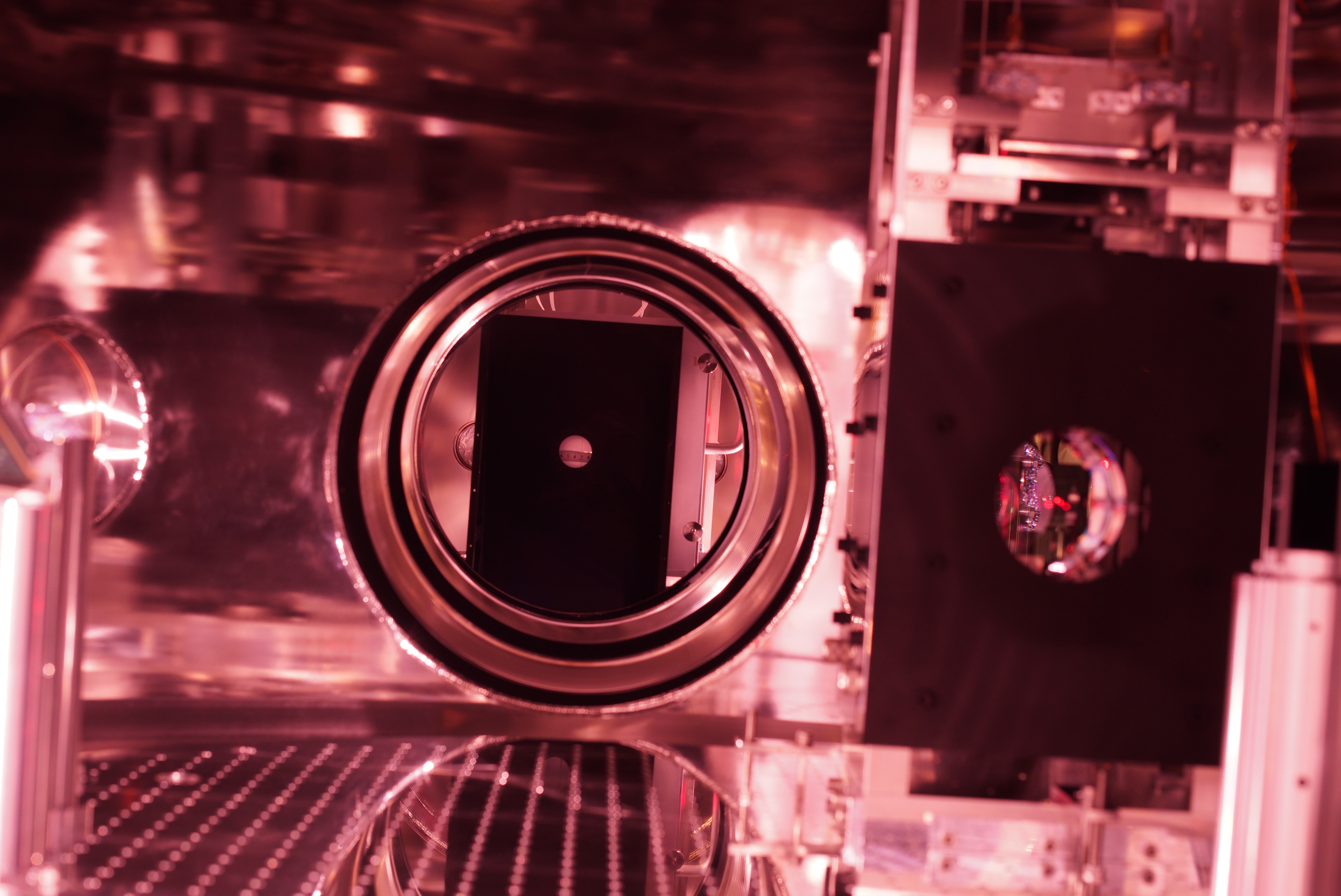
As was confirmed in 29312, we started with checking the beam position at PR2 HR mid baffle aperture, and seemed the spot was 3.5 mm in plus Y direction with respect to the aperture (Fig. 1), as already reported.
PRM mid baffles
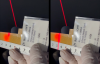
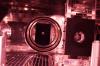
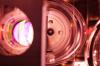
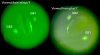
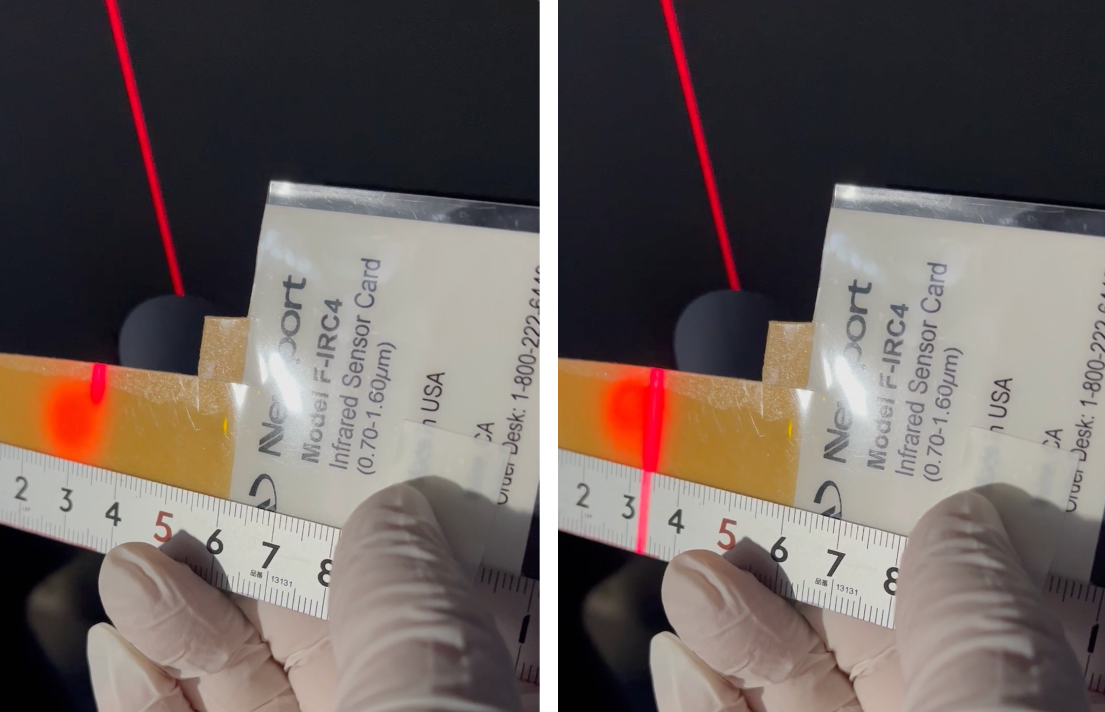
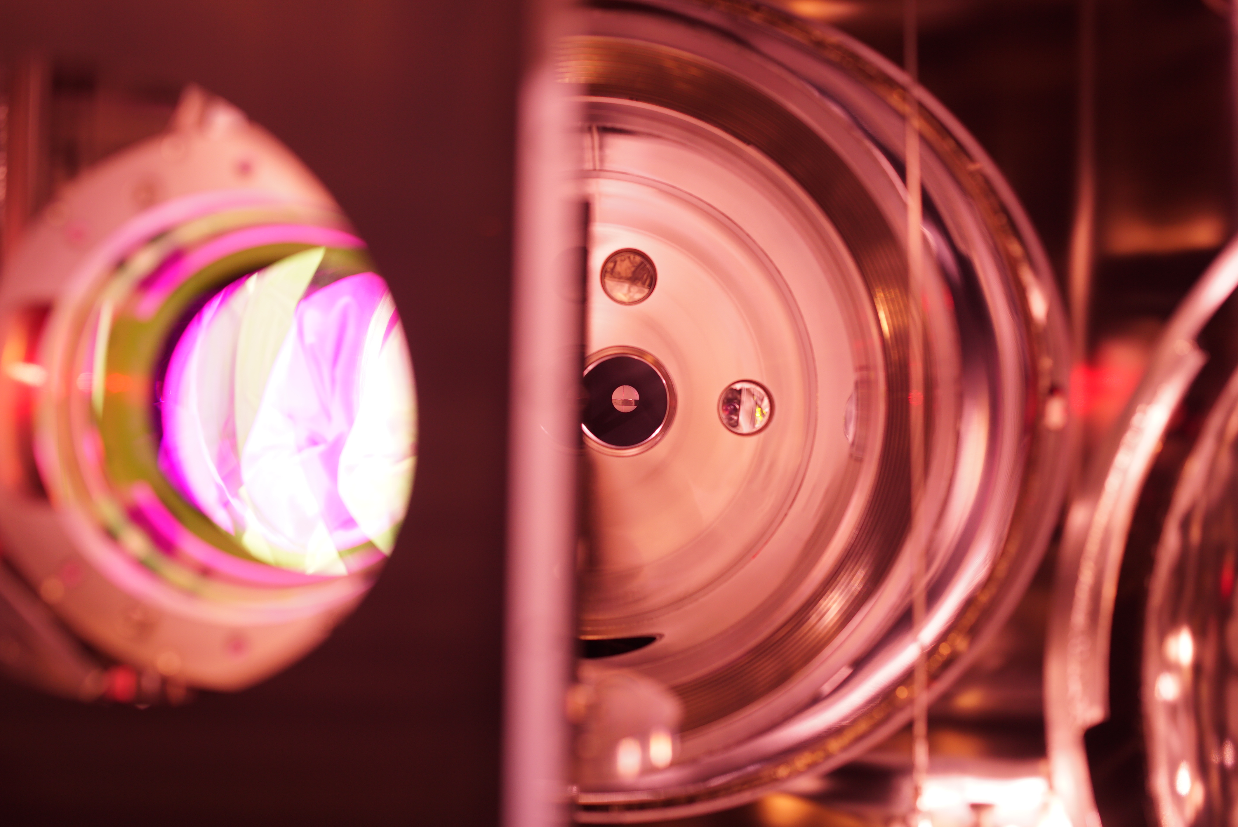
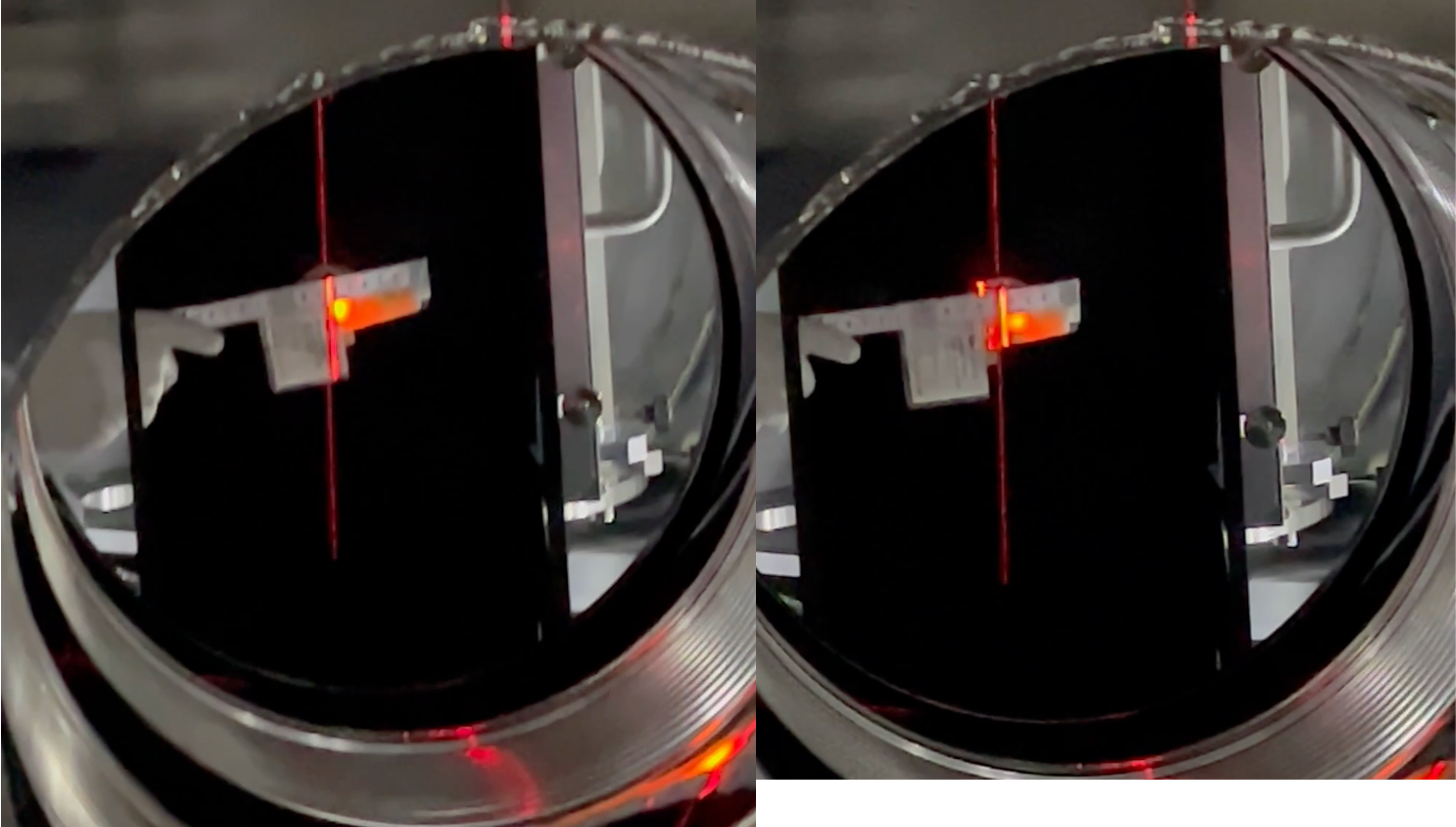
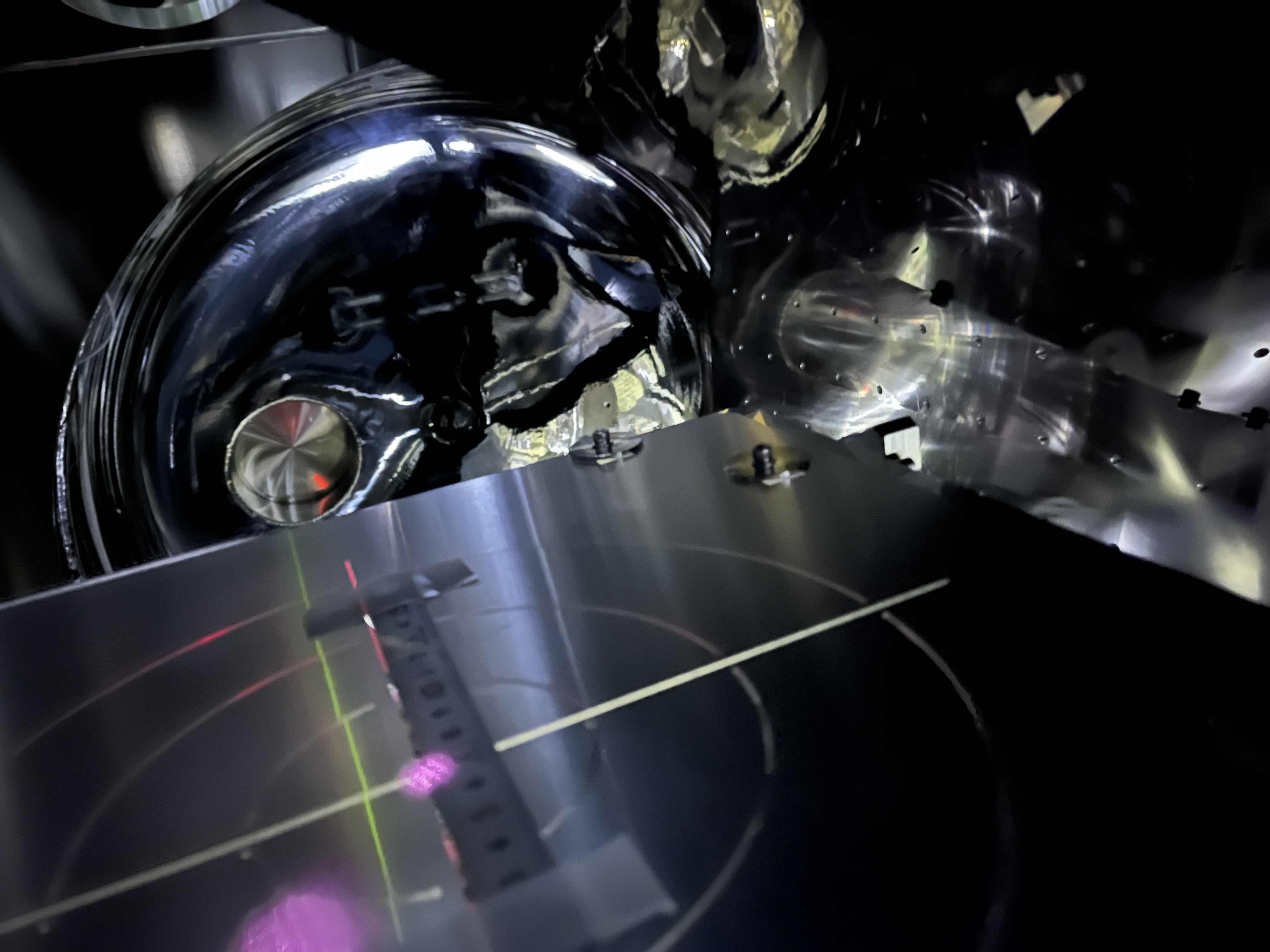
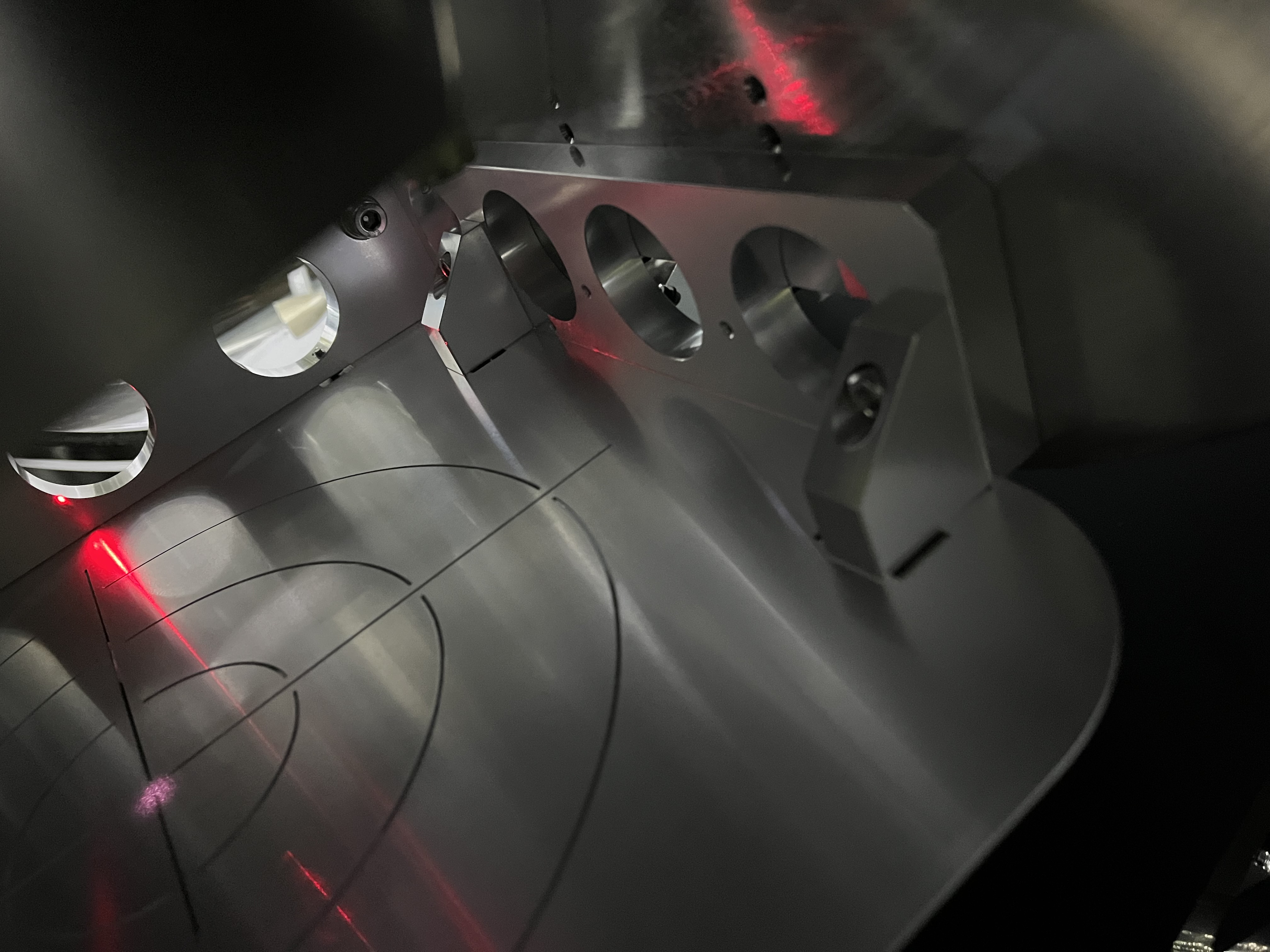
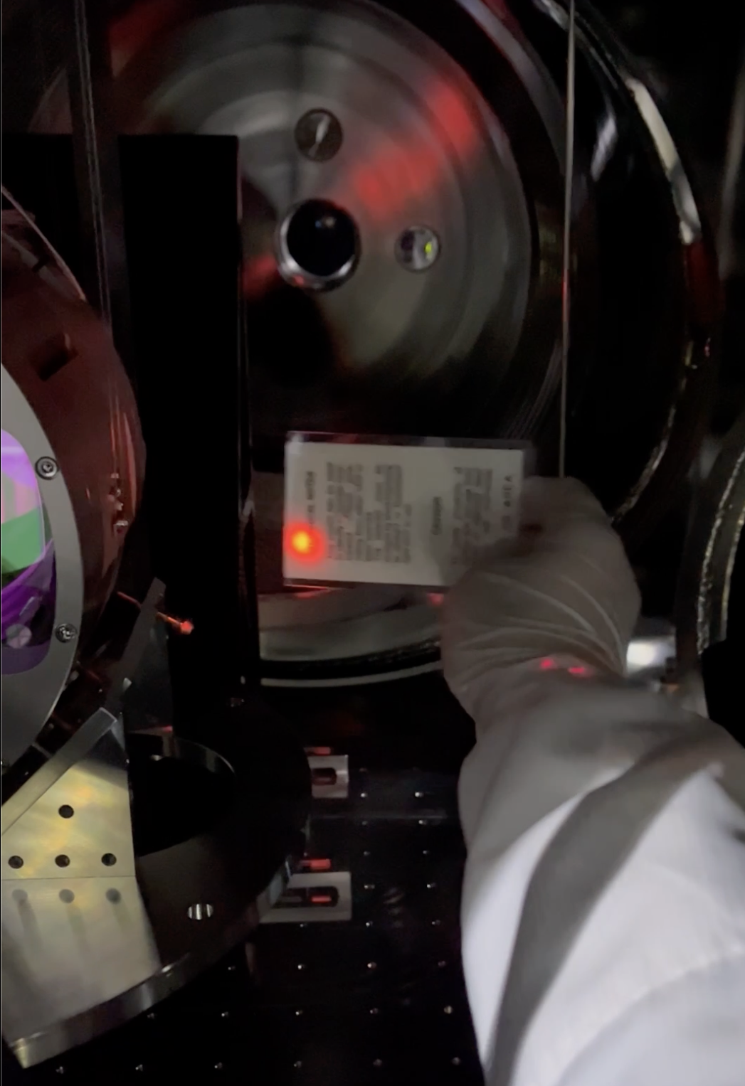
It is difficult to confirm the relative postion of the beam spot at PRM mid baffles due to severe accessibility. We tried several ways (see Fig. 2 and 3, for example; they are respectively of PRM AR and HR side; taken by Miyakawa camera on a tripod; maybe due perspetive, it would be hard to say how much the aperture is dislocated with this way). In the end, using the same method as reported in 29282, we were able to "draw" a vertical line to show the center of PRM AR mid baffle aperture. Then inserting a sensor card with a ruler, we maybe able to say that the beam spot would be ~ 5 mm off-centered in the minus Y direction from this line (Fig. 4), while the noimal number should be 6 mm (JGW-T2214066-v1). So we satisfied at this point.
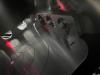
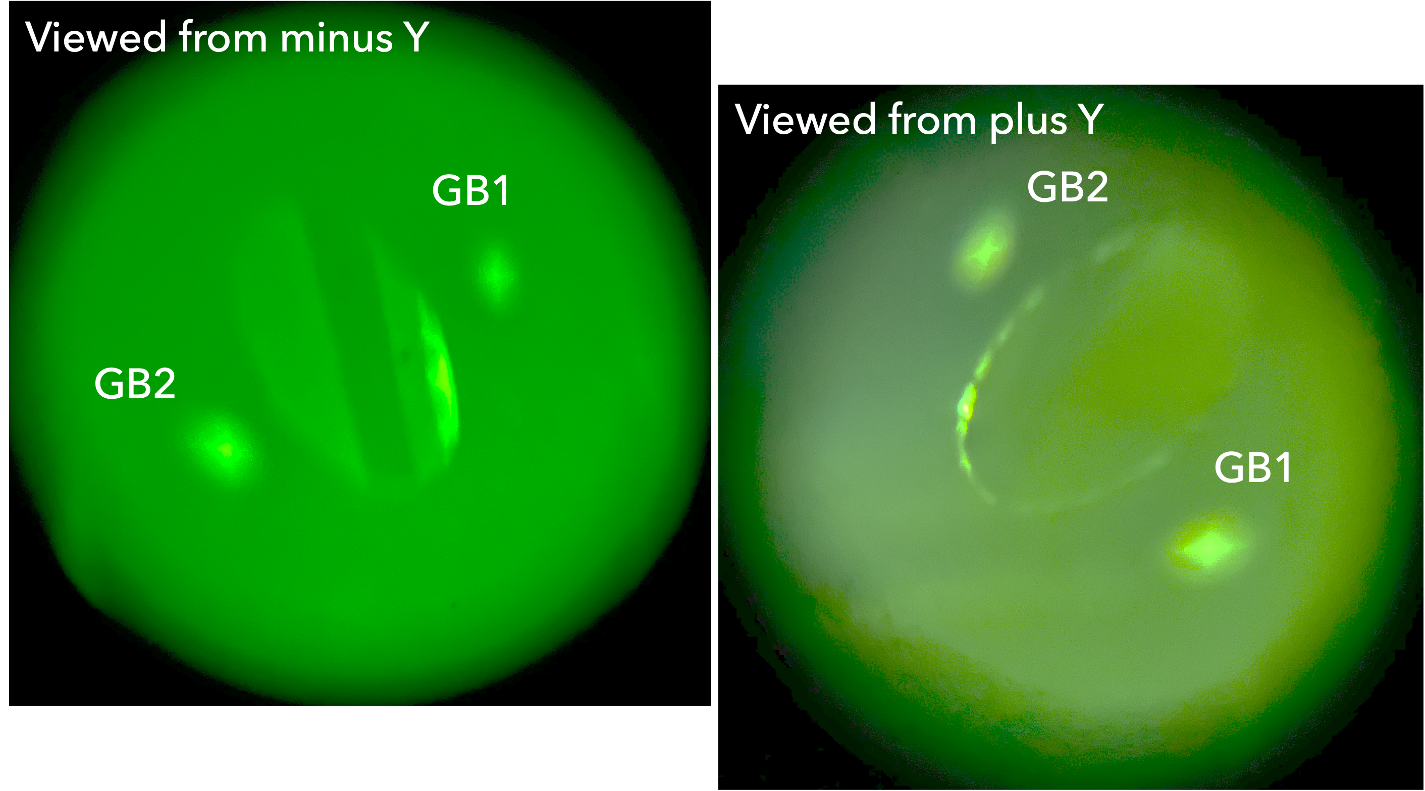
By the way, Fig. 5 is the beam spot on PRM AR target, while Fig. 6 for PRM HR target. As seen, on PRM AR target, the beam spot was mostly centered; on PRM HR target, maybe due to the refraction, the beam spot was a few mm (2.5 mm? see JGW-D2012020-v2) off-centered in the plus Y direction.
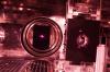
At the same time, ghost beams from PRM on PRM AR mid baffle were checked (Fig. 7). The nominal locations are found in JGW-T2214066-v1, and qualitatively no inconsistency. Also, Fig. 8 was taken from IFI-IMM by Miyakawa IR camera; as seen, "both" side of the aperture edge of PRM AR mid baffle seemed equally shining. The small beam spot left of the main beam spot on PRM would be of surface scatter due to the ghost beam (main incindent -> PRM HR -> -refleceted to AR -> reflected to HR -> exit from AR). When this photo was taken, the camera was set in between the optical beams of IMMT1-to-IMMT2 and IMMT2-to-PRM somehow. The camera hight was somehow set at about the same as those beams. The perspective view seemingly be similar to those in 3D CAD somehow, but it would be difficult to say something definit. At least, qualitatively no inconsistency tendency as follows found; the beam spot on PRM seems left-ward; in the AR baffle aperture, the HR baffle apperture edge could be seen like a crescent...
By the way, in Fig. 8, on the IMMT1 shield, three or four apparent ghost beam spots are seemingly distributed, other than the IMMT1 spot itself. In my observation they are all due to PRM main reflection; When PRM Guadian was at PAY_FLOAT, they were dancing, and stopped when ALIGNED or LOCK_ACQUISITION. My estimation senario is that the PRM backward beam is reflected within IFI, which is made of several optics, and each ghost beam would be reached the IMMT1 shield somehow. One can also see a ghost beam spot in the beam dump in front of IMMT1; this SiC one catches a ghost beam from IFI.
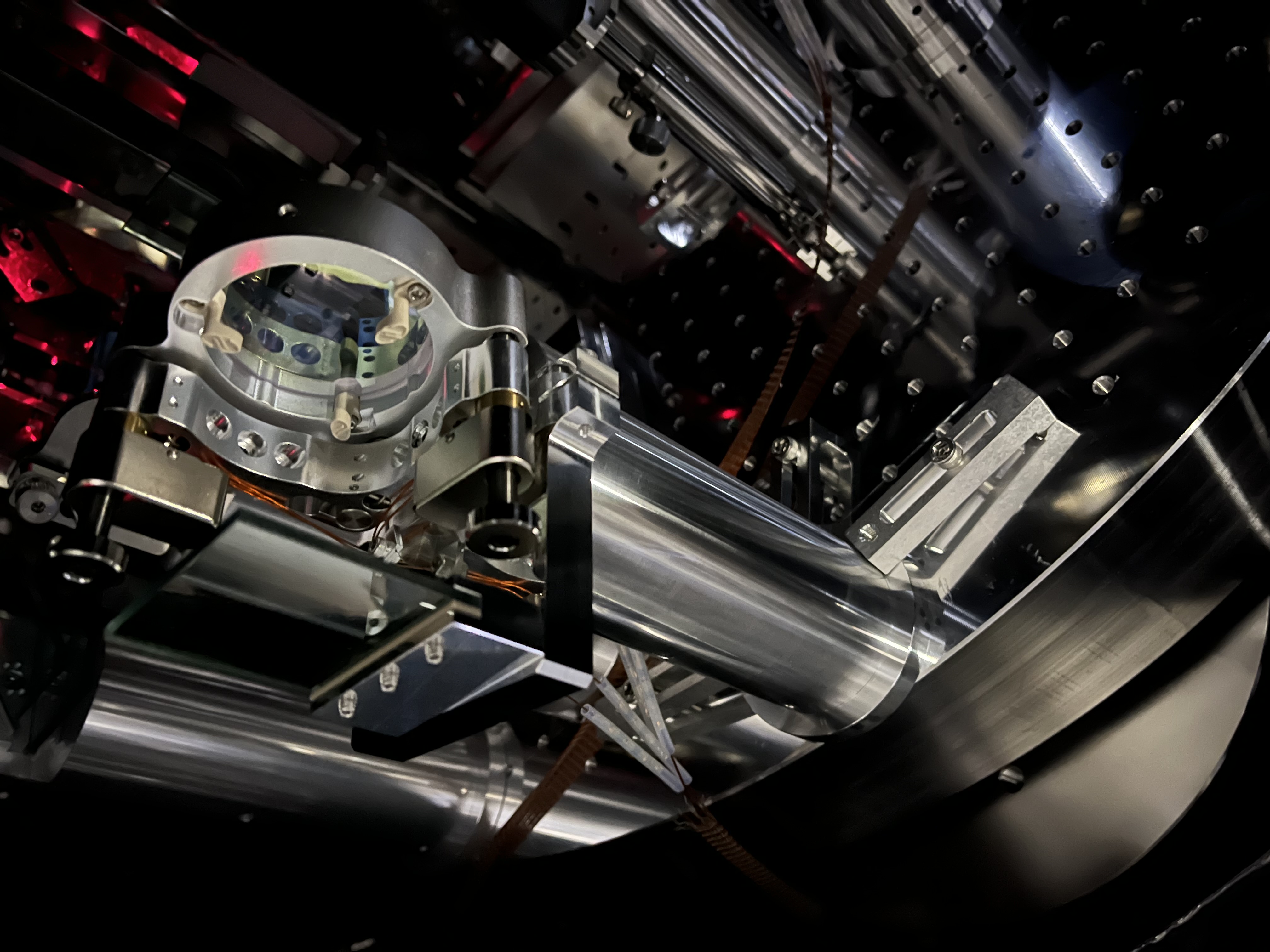
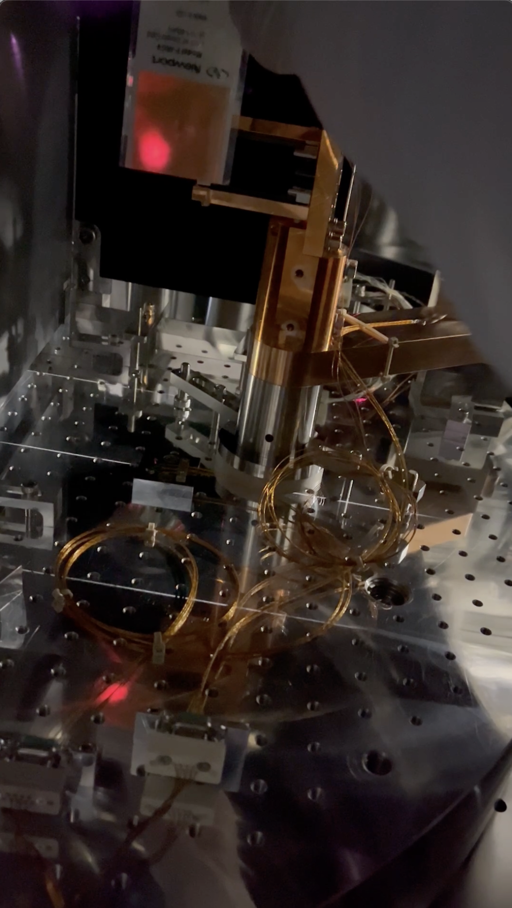
STM2 reinforcement
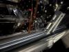
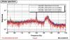
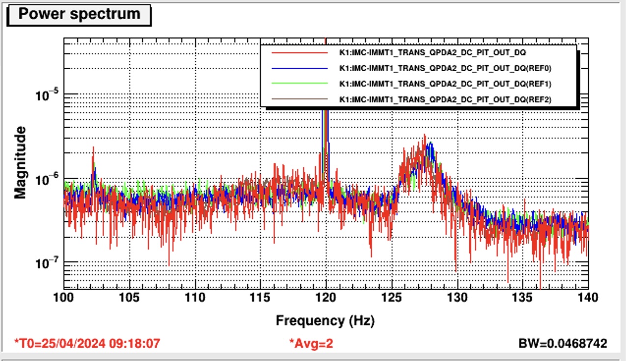
We set another clamp for the pedestal of STM2 (Figs. 9 and 10; the CL-5 type aluminum one in the deeper inside on the table)while carefully looking at IMMT1T QPDs and POP_FORWARD QPDs; this is related to 24703 (ref: 24697 as well, althogh the main topic of this post was not this bump, but some characteristic was mentioned here). Before and after this work, I checked K1:IMC-IMMT1_TRANS_QPDA2_DC_PIT_DQ spectra, but basically no change around 120-130 Hz area; there was a bump (Fig. 11; blue and green are some reference; red is under experiment; the bump slightly shifted after my works/experiments). What I found was that when I only slightly touch a thick cable for picomotors for STM2, this spectum sensitively responded (it was hard to distingush the response whether I would mere shut the optical beam occasionally by my body or not, though...). I checked if this bump would disappear or not by tentatively fixing this cable with white tapes somehow, but not big changes observed. Anyway, the sensitivity seemingly larger than the other point in the IFI chamber I guess.
Please do some cross-check, and hopefully some treatment should be done before closing this area. Currently, maybe most of the frequency band is dominated by acoustic disturbance, so the next time you should make a tube to connect IFI and IMM chambers to avoid this disturbance.
Light beam position near high power beam dump
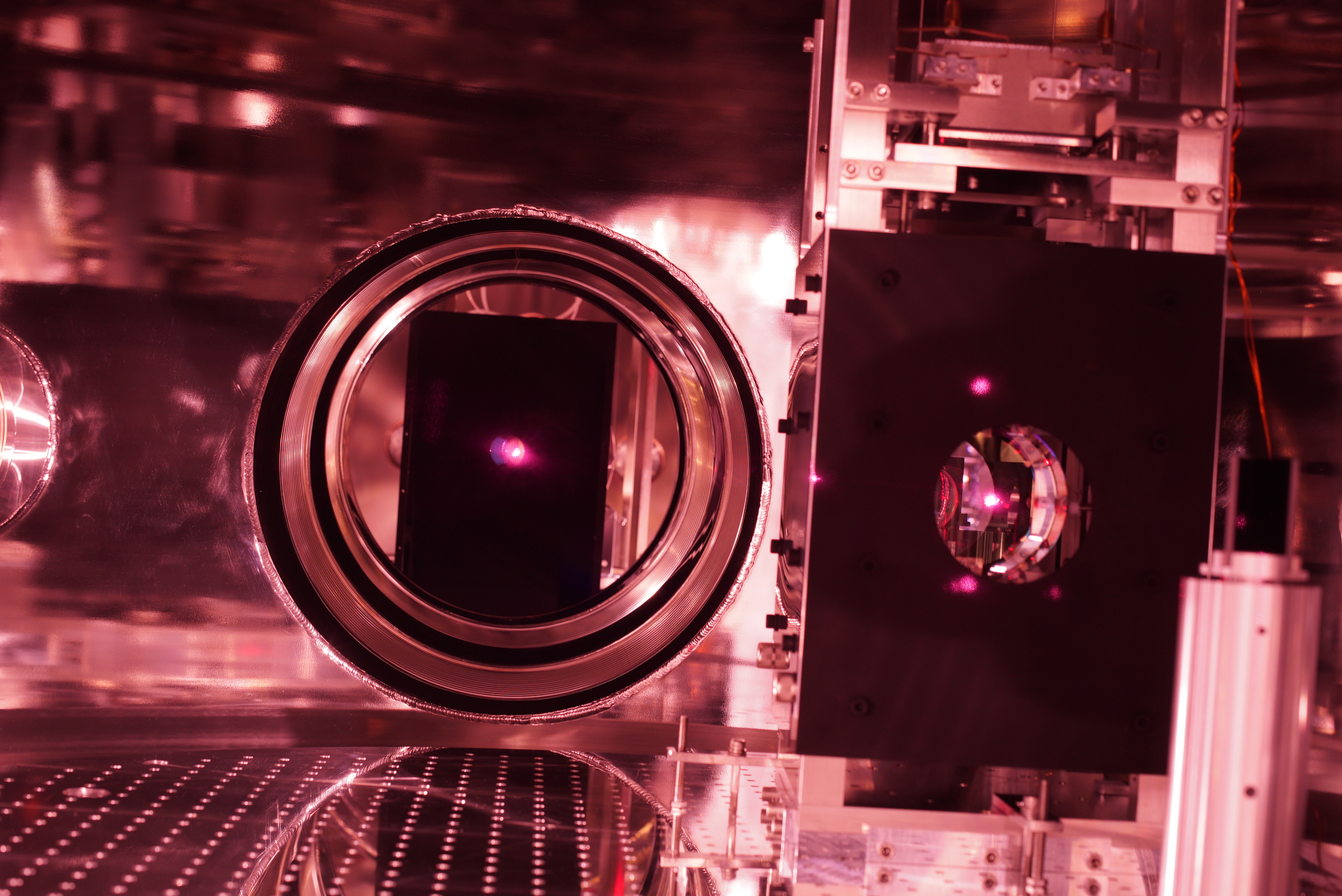
As already reported in 29308, The light beam reflected at IMMT2 was passing through far off high power beam dump so no clip should happen (Fig. 12).
Light beam position near PR3
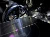
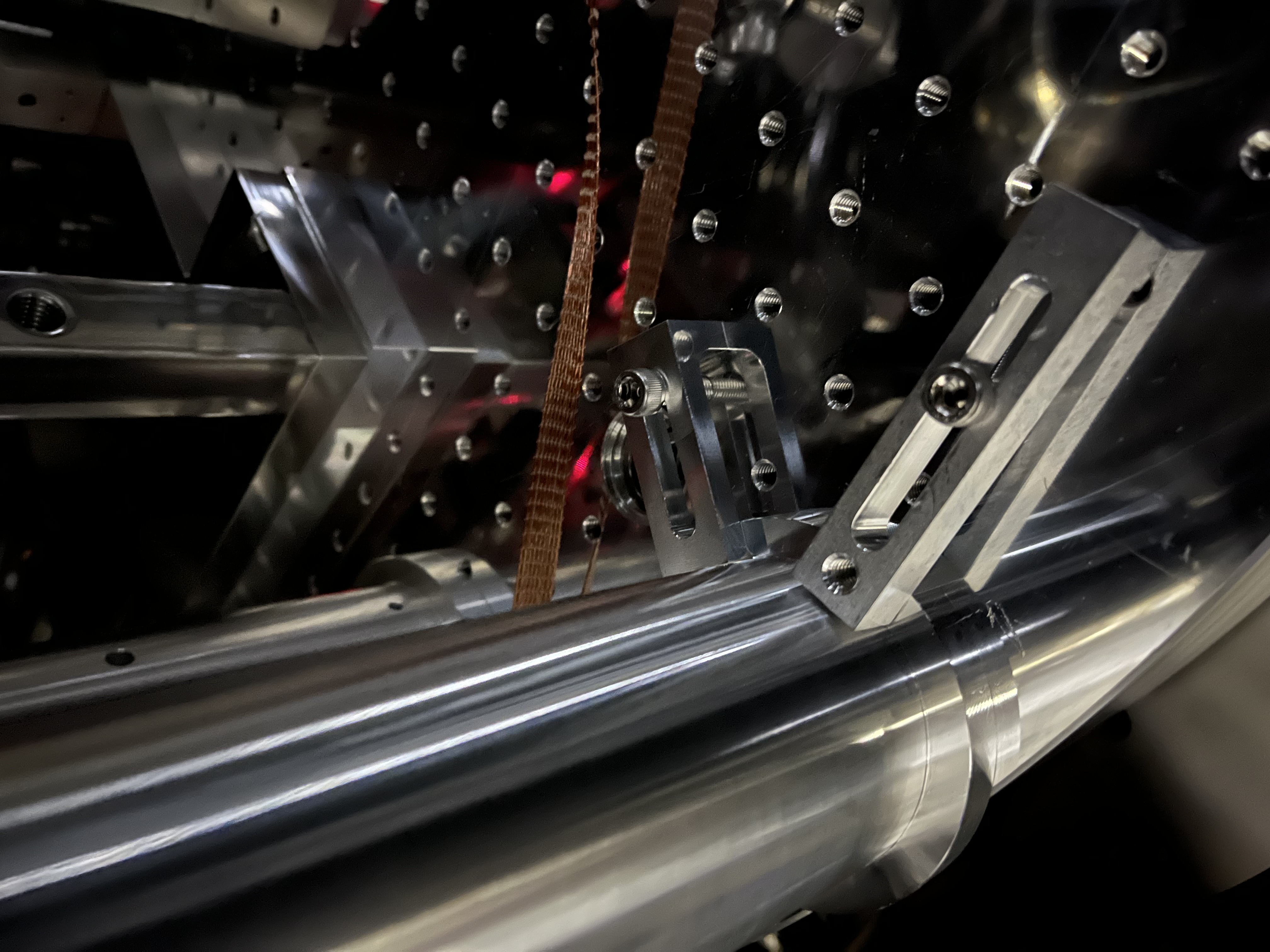
The light beam thourgh PRM was passing through far off PR3's recoil mass (Fig. 13). From this, the open angle of the light beams connecting PRM-PR2-PR3 should be not 0.013 rad, but should be close to the nominal designed value, 0.02 rad; PR2-PR3 distance is about 11 m (see wiki), so 0.02 rad open angle means the beam separation must be 0.02*11 = 220 mm or so, which would be consistent with this photo somehow.
Note
A strange thing; according to JGW-T2214066-v1, the PRM AR and HR mid baffle should be displaced about 9.3 mm nominally; the HR one should be shifted in the minus Y direction. But today we found that there was only ~3 mm displacement. Where 6 mm gap went..? Is Fig. 3 (the center of the target seemd offcententered to the aperture, but I cannot discard this is due to perspective or parallax) related to this issue? Actually the beam spot on this target is a few mm in the plus Y direction according to Fig. 6, but may not be 6 mm. At any rate, 6 mm shifting would be too much. That's why we did not touch both sides of PRM mid baffles.

