Ushiba (remote), N. Satō, Akutsu; following 21638
Summary
Adjusted input beam axis with referring POP_FORWARD QPDs, as we found one of ghost beams behind IMMT1 illuminate the boundary of IMMT1-ISS-POM and its beam dump. After that, IMMT1 oplev, IMMT2 oplev, and IMMT1T QPD 1 and 2 were re-centered.
Sympton
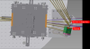
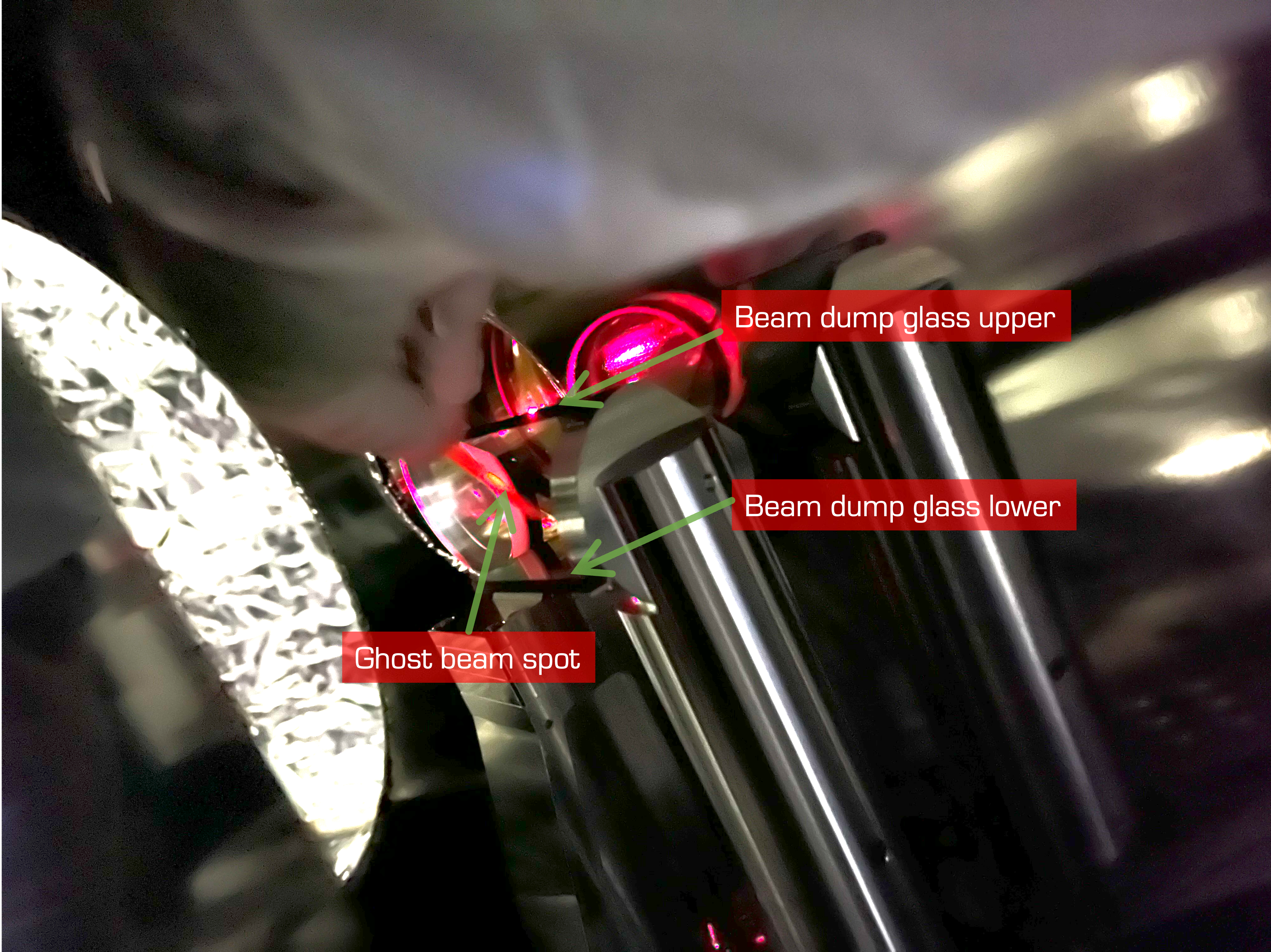
While the yesterdays's work (21638), it was found that one of the ghost beams behind IMMT1 ("this one" in Fig. 1) was not properly caught by the relavant beam dump, but slightly shifted in +Y direction, so it illuminated just both edges of the IMMT1-ISS-POM and this neighboring beam dump. In fact, we have known the IMMT1-ISS beam itslef seemed slightly shifted in +Y direction; this beam should illuminate this mirror about 20mm away from the mirror edge, but about it measured about 15-18 mm. It was also referred in the last week, see 21578, and self-questioned "should we need to re-adjust these slightly?" Now, the answer seems yes, we need...
Remedy
To mitigate this situation, there are several options, like:
- Opt 1: adjust whole the input beam axis from the PSL room and including IMC taking advantage of the ASC loop
- Opt 2: adjust STM2 only
- Opt 3: adjust the IMMT1-ISS-POM and the neighboring beam dump
We firstly tried option 1 by adding certain offset to the ASC control loop, but we immediately found that we would need to touch PZT1 in the PSL room (this is not the one on the periscope), otherwise the feedback got saturated. Note that PZT1 is not included in the IMC ASC. So we gave up and reverted everything.
We need to choose option 2 or 3. Option 3 could affect also IMMT1 oplev beam axis, which would mean we would lost one of references, while what we tried to do is principlely losing some references such as POP_FORWARD and IMMT1_TRANS. We would like to keep as much reference as possible, and option 2 is also easy to access, so, we chose option 2.
Firstly I tried to adjust STM2 yaw by my hand, but immediately I learn it is too scare, and so we deteremined to use picomotors for STM2. For fool proof safety, the picomotor cables are not connected after the flange, so I brought a setup of the picomotor driver with a joystick, and connected all. By the way, about the channel assign, we found that STM2-1 is yaw, and STM2-2 is pitch today. Hmm...
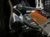
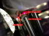
Adjusting STM2 yaw to the level out of the linear response of the IMMT1T QPDs, each time, I checked where the beam spots were on IMMT1-ISS-POM. This activity made POP_FORWARD shifted as well, of course. So I stopped before we totally lose the POP_FORWARD references. In my eyeball, the IMMT1-ISS beam spot on this mirror came close to the designed location (see Fig. 2 and compare with 19585), and also the ghost beam seemed caught properly with the neibouring beam dump (Fig. 3), so I satisfied.
Final check
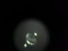
As starting final check, Ushiba-kun manually adjusted IMMT1 and 2 so that the both POP_FORWARD QPDs got centered. Then, I checked if the IR main beam would center on IMMT2, and also the beam situation around PRM; note that the beam should go through the RPM mid-baffle AR aperture in 6-mm offset, and this baffle should catch two ghost beams (mainly); compare with 20797 and Fig. 4. They seemed all ok. Then, we zeroed IMMT1T QPDs as we believed this should be the new reference. Also we zeroed IMMT1 oplev and IMM2 oplev. Ushiba-kun recorded good values.