N. Sato, Uehara, Akutsu; also see 21545 for the preparation. See JGW-T2112509.
Summary
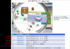
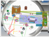
The work progress is shown in Fig. 1, which is modified from the document attached in 21545. In the IFI chamber, we have installed several beam dumps, and found additional ghost beams; due to real-world difficulties, we need much more time to tame those ghost beams yet. We have also installed a viewport window to extract IFI-pickoff beam prepared in 21476, which is now freely fly in the air, so be careful (illuminating a wall on the IFO_REFL table). All these works were done together with monitoring IMMT1T QPD and POP_FORWARD QPDs so that they won't be out of the ranges.
Detailes
STM1
Beam dump #1 in Fig. 1. This beam dump has two KG5 plates as beam dumps on the same plate. After several tries to adjust these plate alignment and positons not to intefere against the already-existing mechacnical stuffs like the mirror holder and the picomotors, the beam dump setup was fixed to the pillar of STM1.
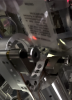
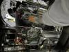
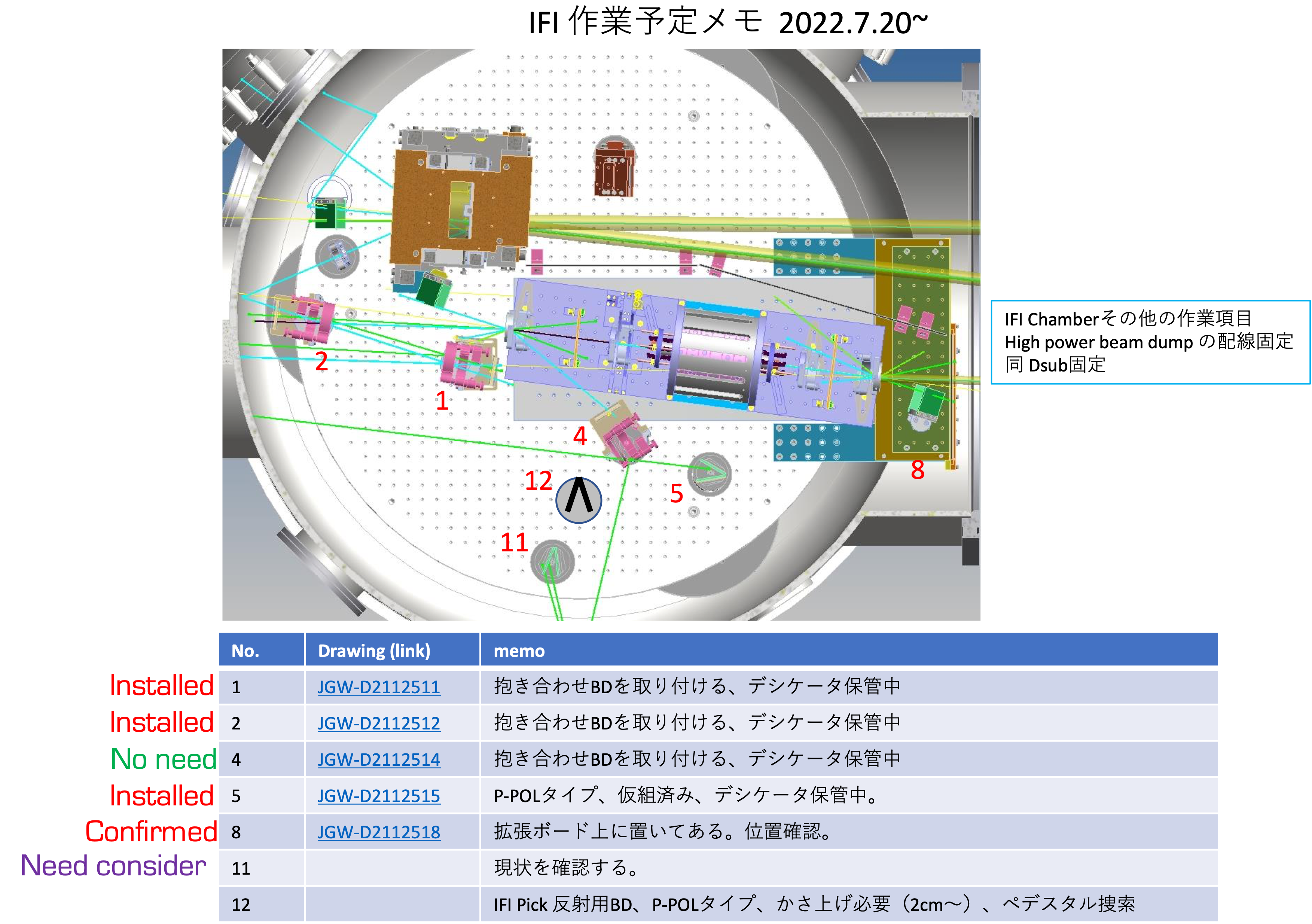
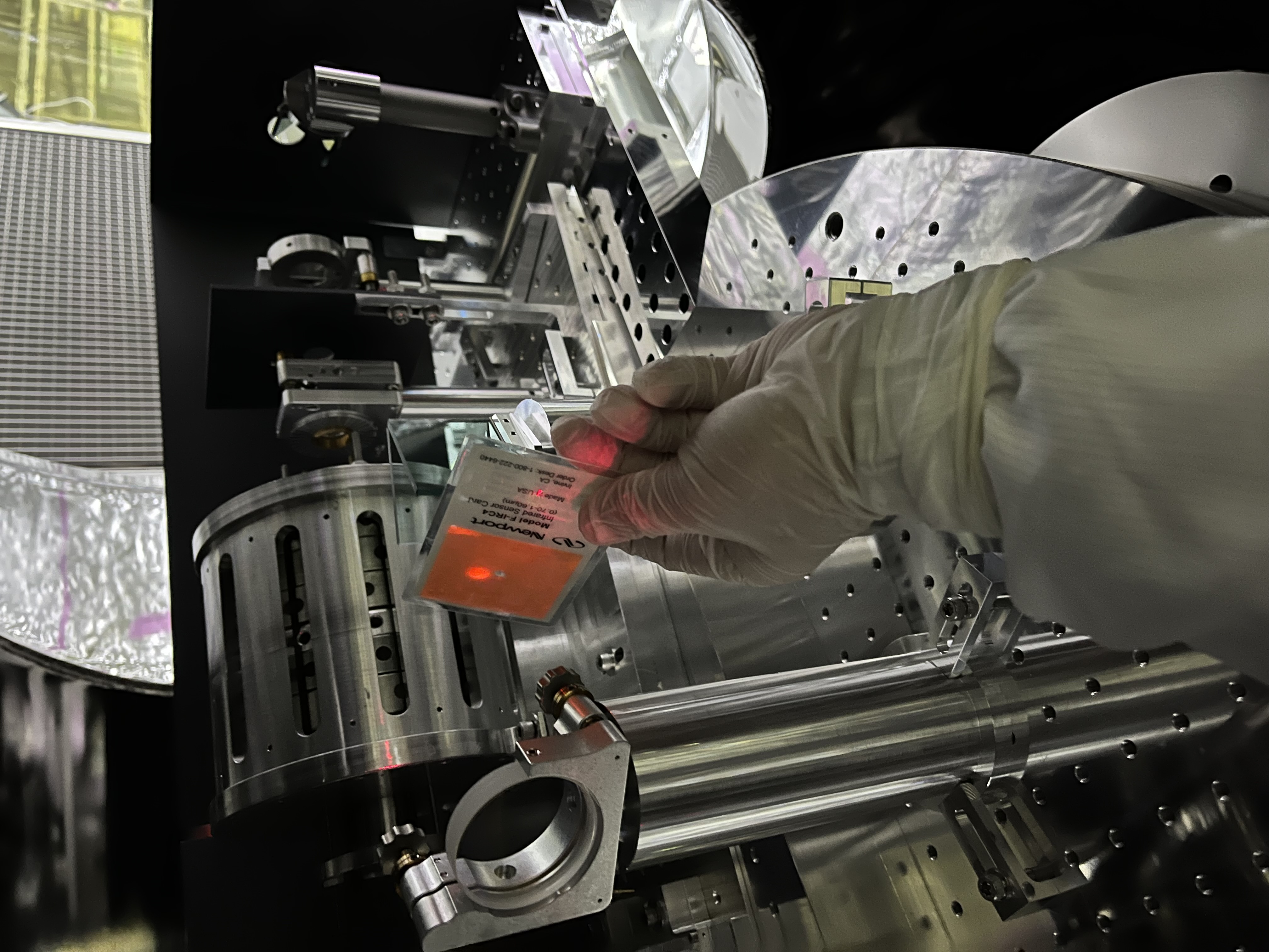
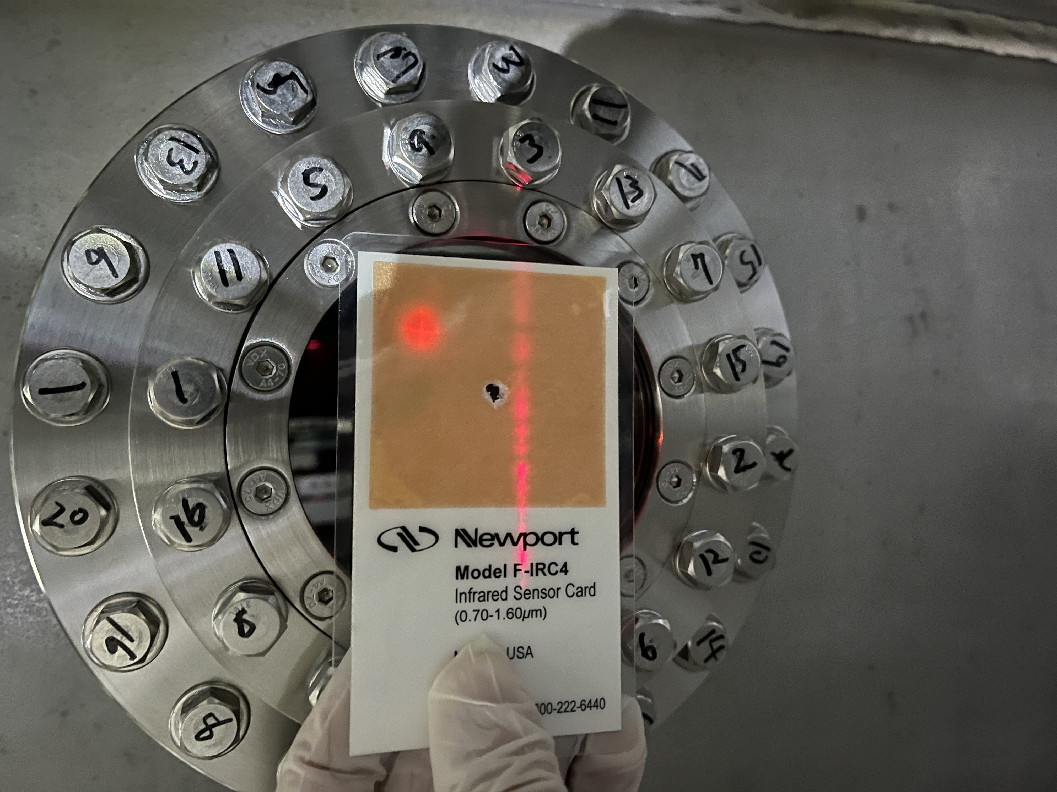
- The ghost beam (from CWP1) illuminating the dump at the side of STM1 could be seen with a sensor card (Fig. 2), so we adjusted the location of the KG5 plate. This ghost beam made another issue to be reported later.
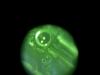
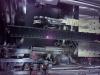
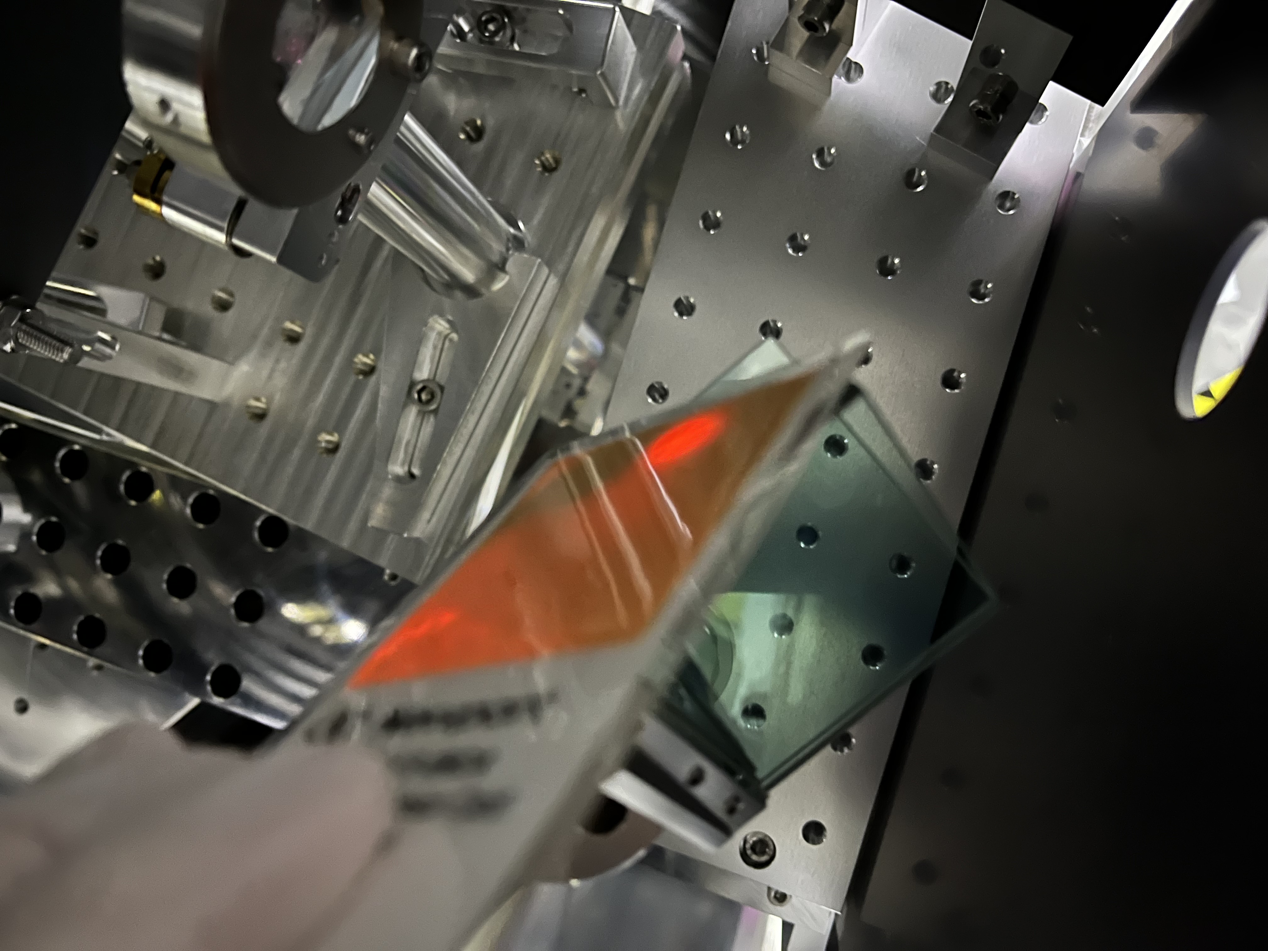
- About the beam dump behind STM1, I confiremd that it caught the STM1 transmission beams (Fig. 3), which were faint. But it appears this is not the main issue, to be reported later; in short, I found more higher power ghost light (not "beams"..., unfortunately...).
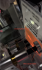
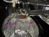
- By the way, the backward beam spot on STM1 seems too much at edge (the left beam spot on STM1 in Fig. 4), while the forward beam seems too much centered. Do we need to modifiy this to move both beam spots close to the center of STM1?
- A non-vacuum compatible remnant in front of STM1 structure was detached.
STM2
Beam dump #2 in Fig. 1, which caught backward and forward transmission beam spots (Fig. 5).
POM2 side
Beam dump #4; although powering up the input beam power as reported (21563), I could not see any such ghost beam lines. So I judged that this beam dump would not be required, so we did not install it.
POM2 transmission
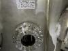
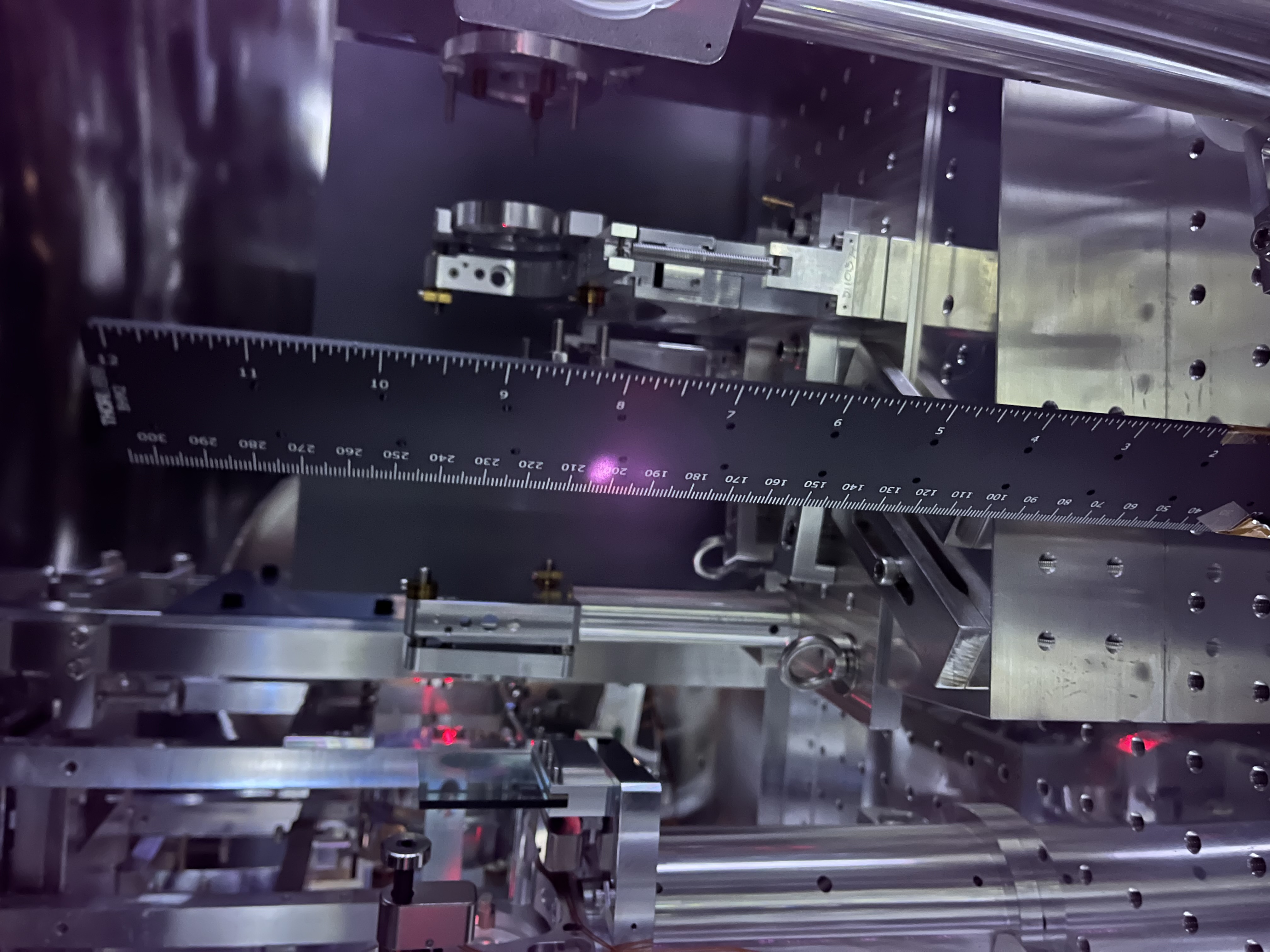
Beam dump #5. Before installing this, we found that the height of the beam illuminating POM2 (and so, its transmission) seemed lower than the design height (210 mm) about 7 mm (Fig. 6), and so we tuned the beam dump height here. The beam dump was located almost the same location as shown in Fig. 1 and possible to catch the aimed ghost beam (Fig. 7).
CWP2
Beam dump #8. We confirmed this beam dump caught the aimed ghost beam (Fig. 8).
Viewport window for extracting IFI pick off
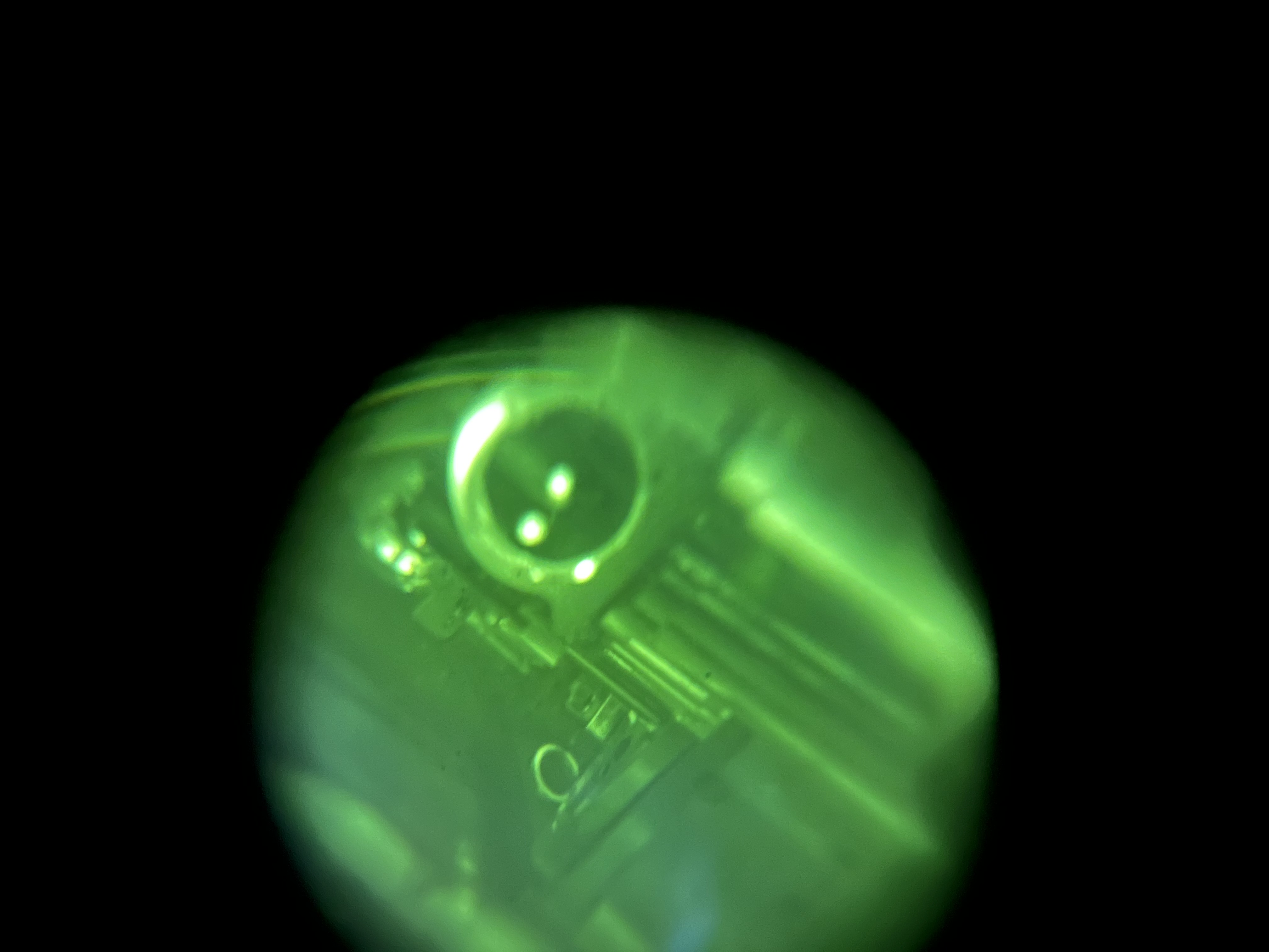
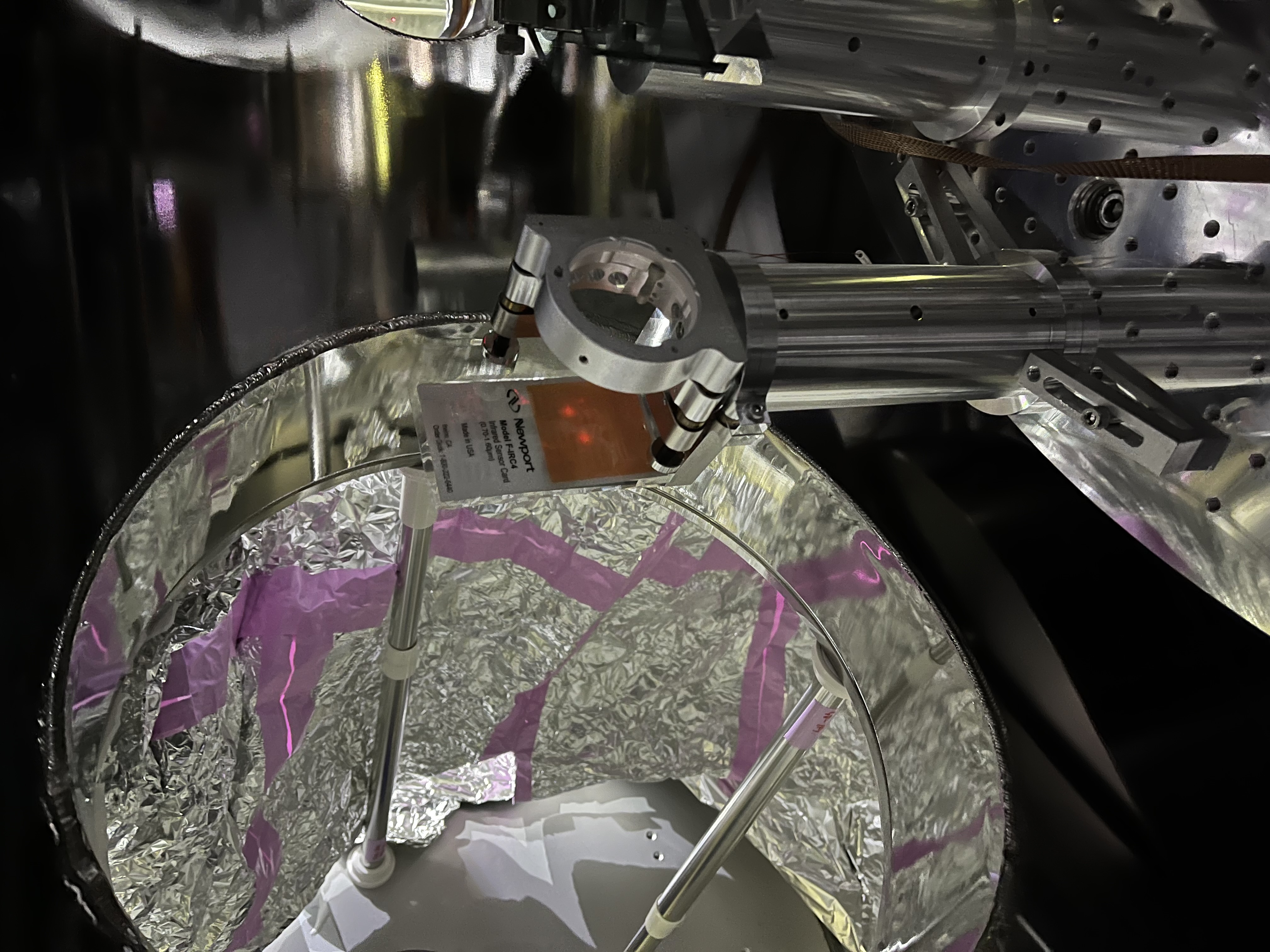
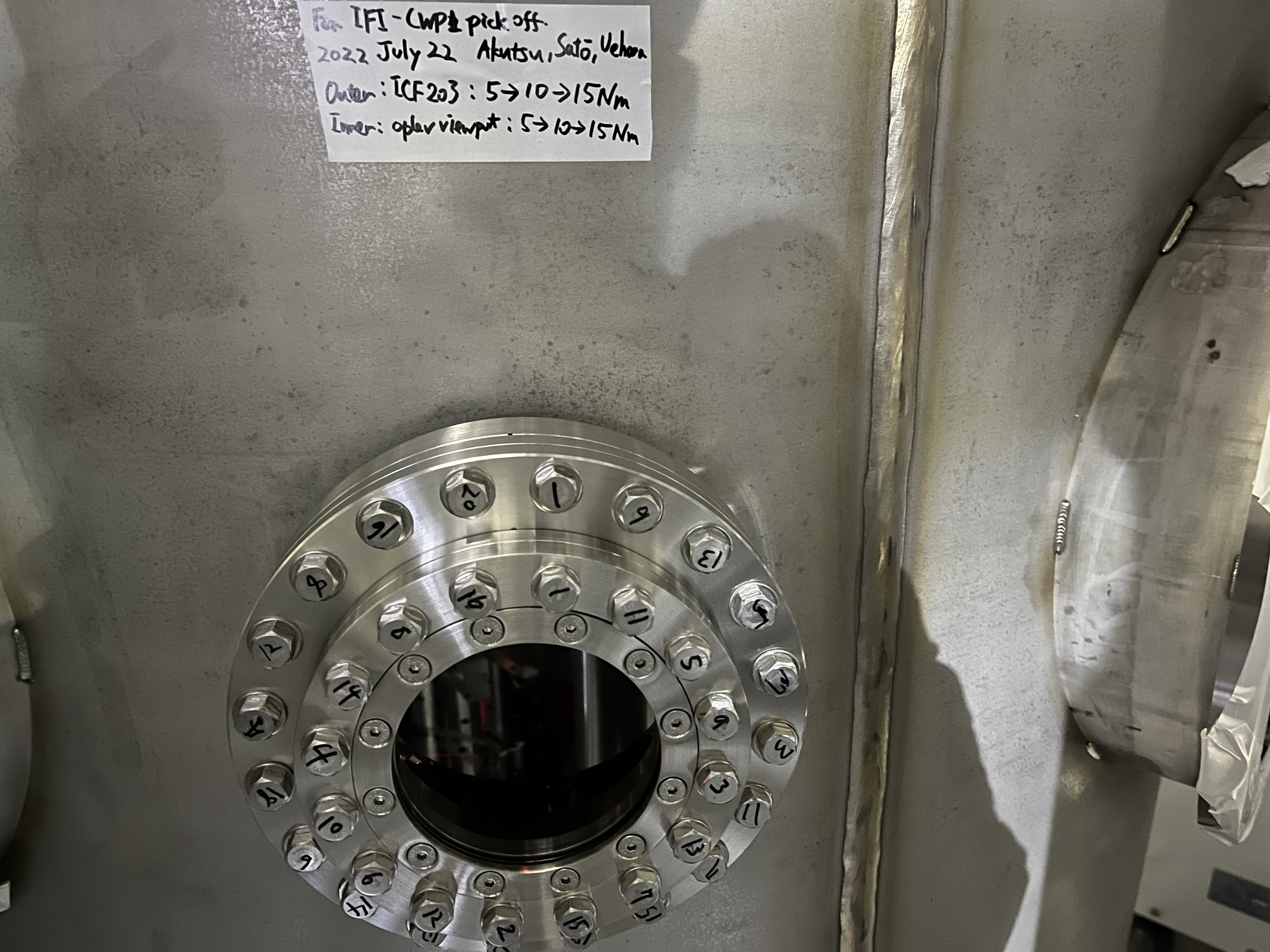
We have installed a viewport window (that was for oplev, but used for this purpose here). The relevant flange was ICF203, so we installed ICF203-ICF152 adapter flange, on which this IFC152 window was installed (Figs. 9 and 10).
Additional issues!
Once a ghost beam is caught, additional ghost beam is found. It says the endless commissioning finally has started.
- We found two ghost beams illuminating the bottom of STM1 (Fig. 11); the transmission of these beams can be also seen in Fig. 3 lower. Tracing these beams, I confirmed they were made within Faraday rotater (not CWP1 this time). Anyway, they can be seen with a sensor card even the current input power, they have to be properly dealt with; in other words, we may need additional new mechanism to be newly designed.
- The installed viewport window for extracting the IFI pick beam made additional ghost beams toward within the IFI chamber, as aniticipated (red GB; ghost beam in Fig. 12). These ghost beams will be caught by beam dump #12 in Fig. 1 later.
- Also shown in Fig. 12 in yellow lines; I found additional new ghost beam in the chamber; tracing it, I confirmed that this was made by reflected at the KG5 plate located at STM1 side, and reflected by the IFI-pickoff mirror. Hmmm....
- As was already discussed, the forward and backward beam spots on STM1 might have to be adjusted... see again Fig. 4.


