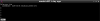
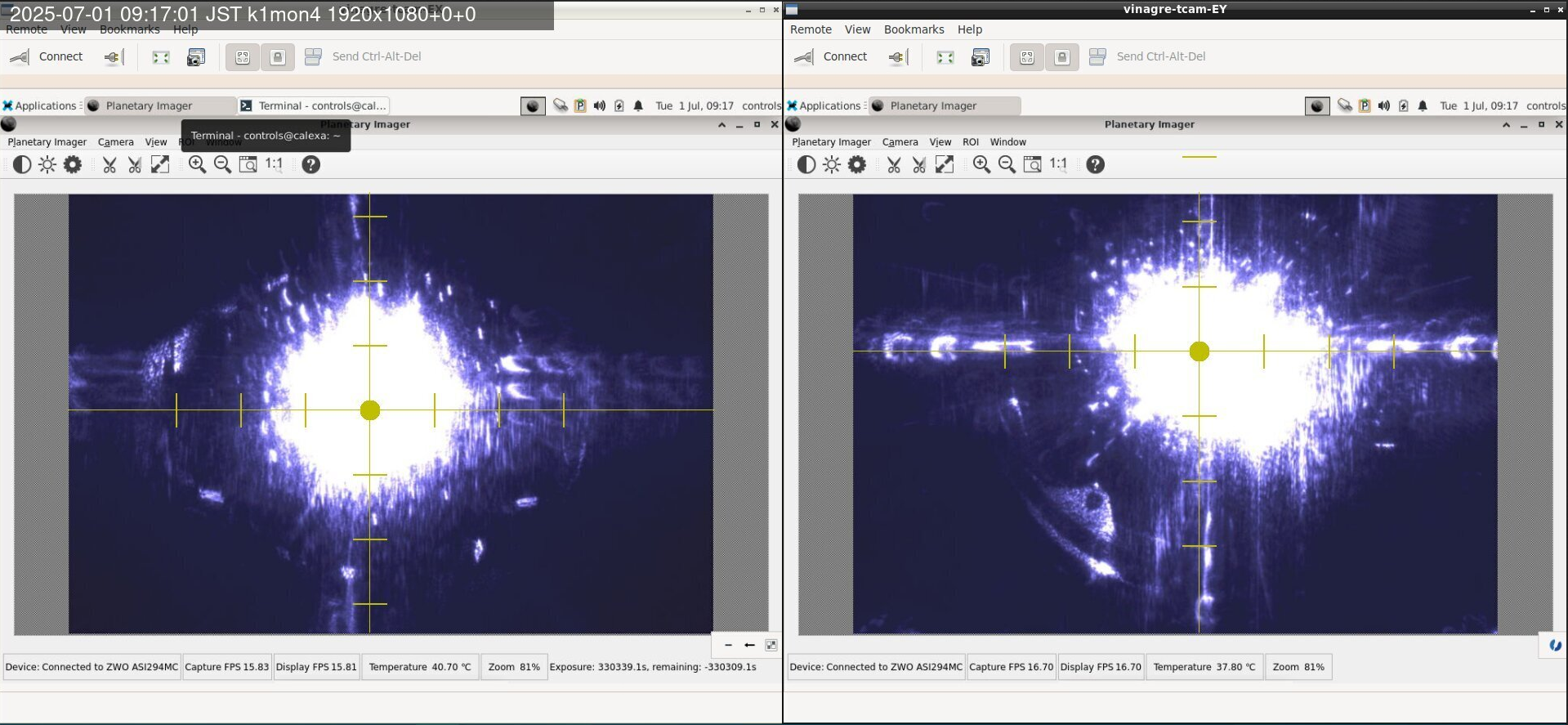
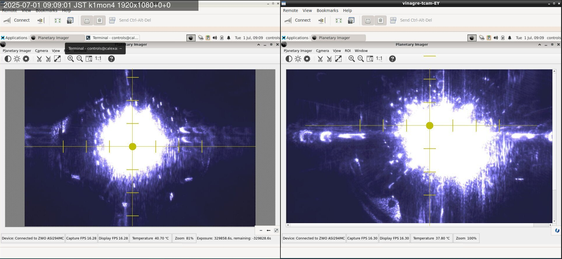
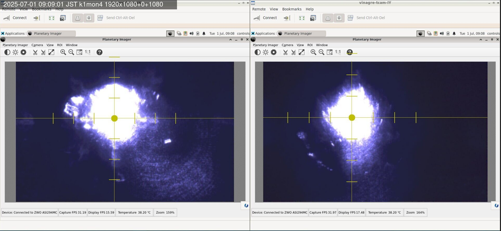
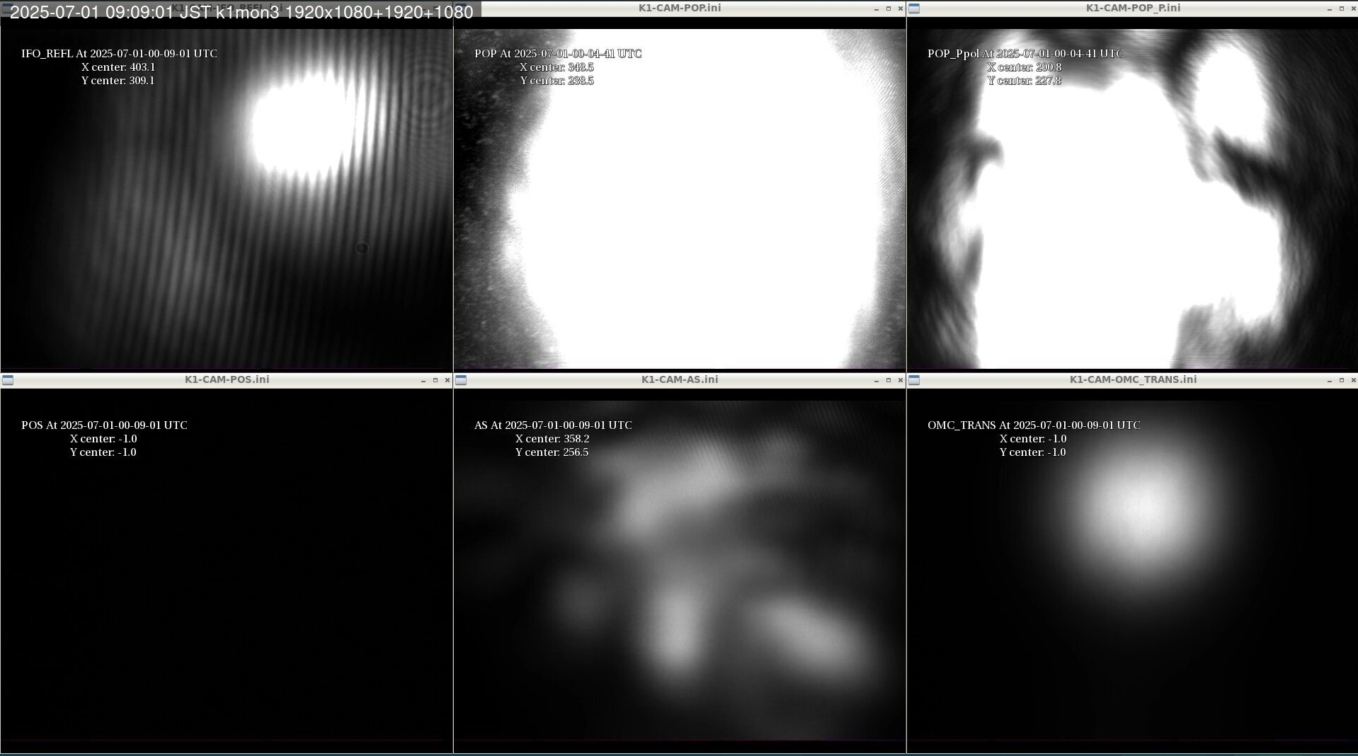
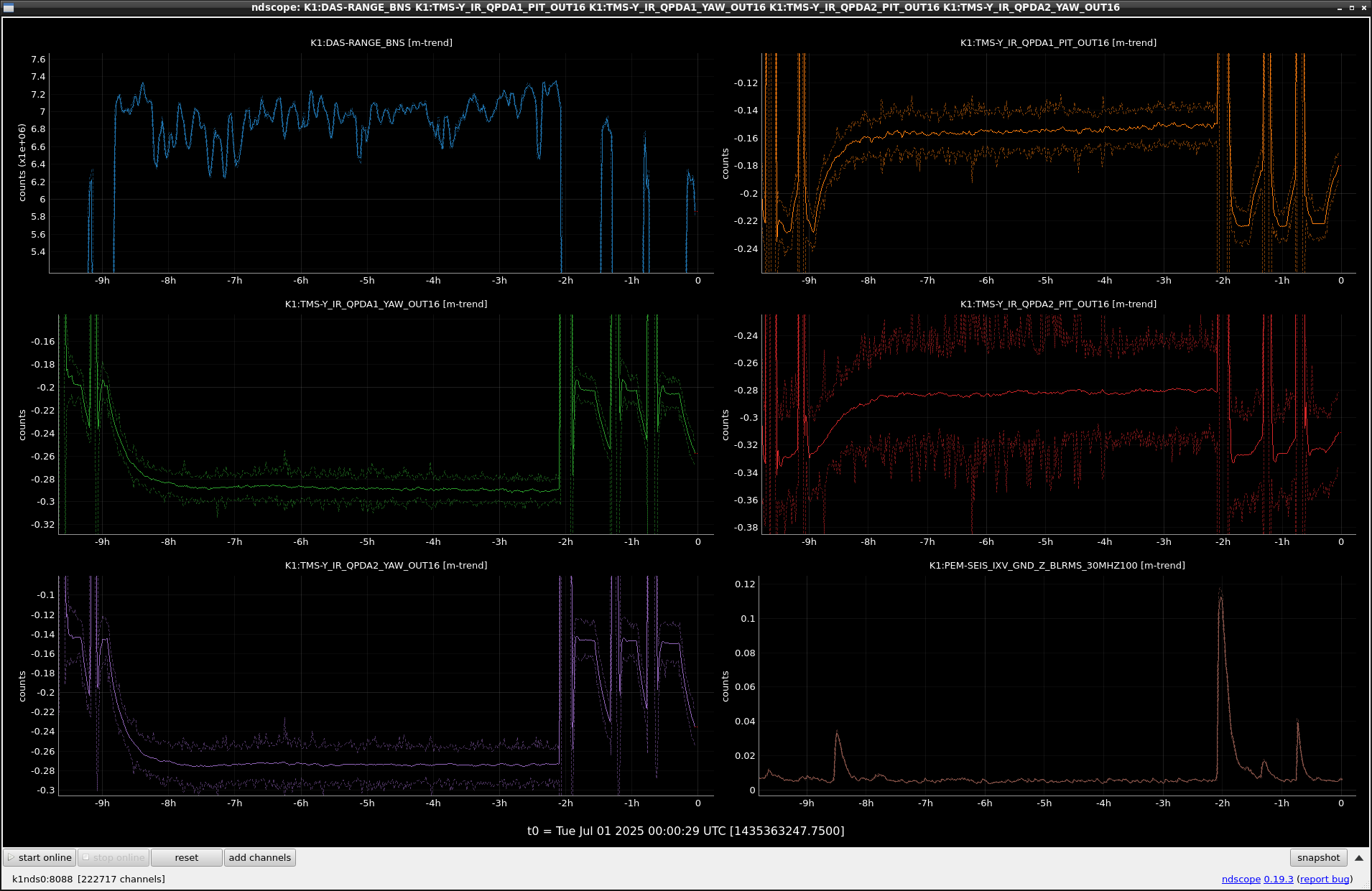
I checked the TMSY IR QPD, and it would be shifted in two hours ago and now trying to back to better position.(Fig.4.)
Shift would be due to the earthquake
And detection range was slightly bad compared from stable lock.
Should we add several flag for this event?

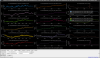
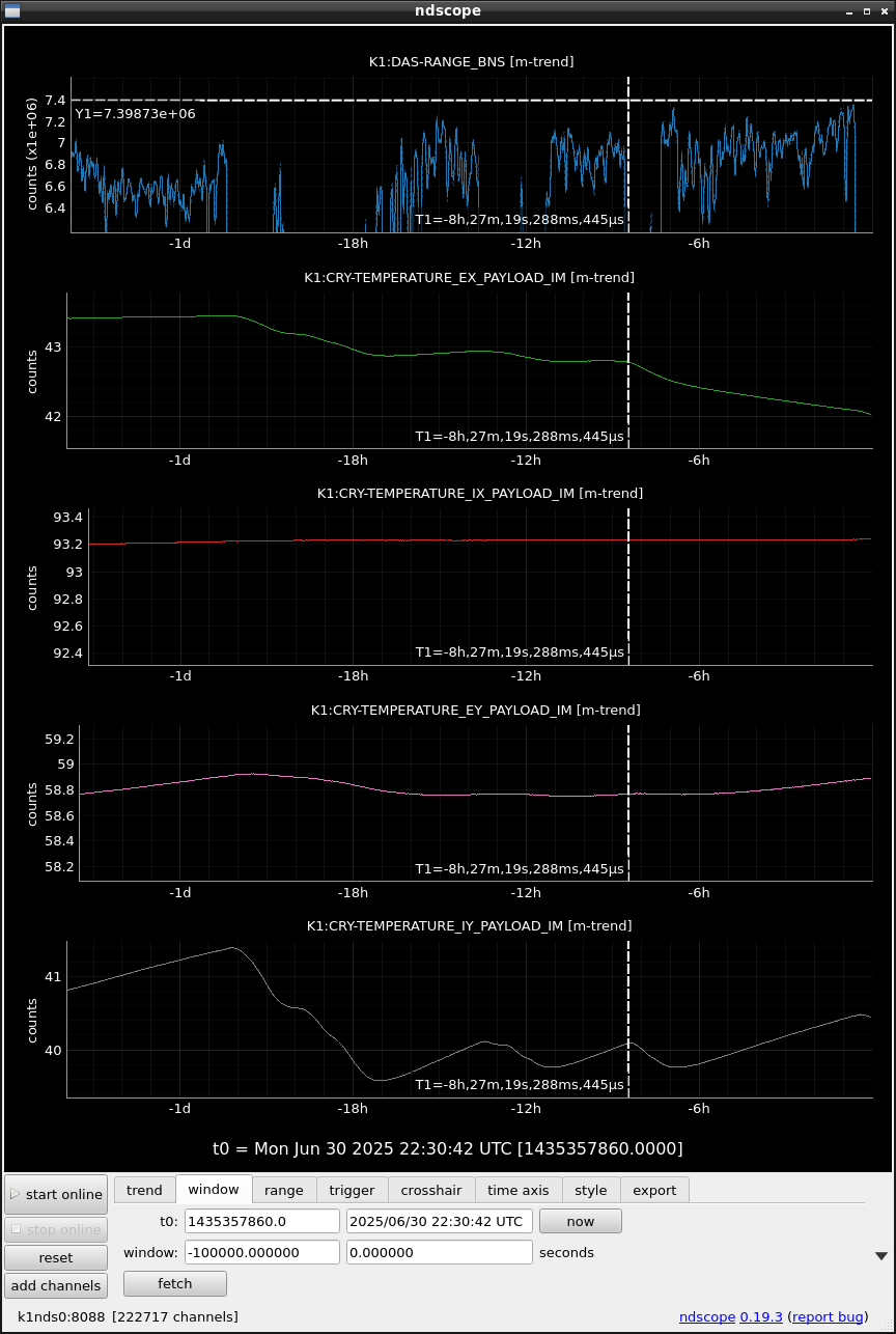
In last night, I reduced the voltage to heaters for IY and EX IM by ~ 0.3V to reduce the temperature.
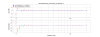
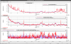
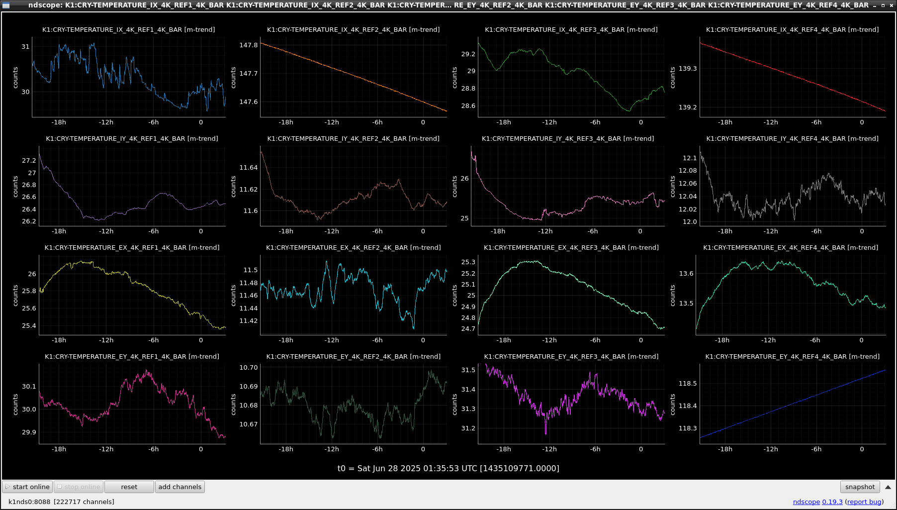
Fig.1 shows the relation between IM temperatures and BNS sensitivity. IY temp kept increasing by ~ 1K. On the other hand, the EX temp decreased by 1K.
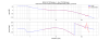
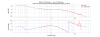
Fig.2 shows a longer trend. It is difficult to find remarkable relations.
The best BNS sensitivity is 7.35Mpc just before the lock loss. We need calibration?
- Each value is estimated based on JGW-L2314903.
- Estimated values by Pcal and Free-swing are consistent with each other at approximately 3%.
- Previous full measurement which is the reference of comparison is klog#34033.
- There is no significant change in all parameters.
- Numbers in parentheses indicate a number of engaged de-whitening filters.
- Low-frequency (<1Hz) zero/pole in disengaged de-whitening filters (see also klog#33874) are compensated based on circuit measurement only for ETMX in klog#34229 and klog#34244.
- So this effect must be considered for other suspensions.
| Free-swing | XPcal | Diff. from prev. | Figures | |
|---|---|---|---|---|
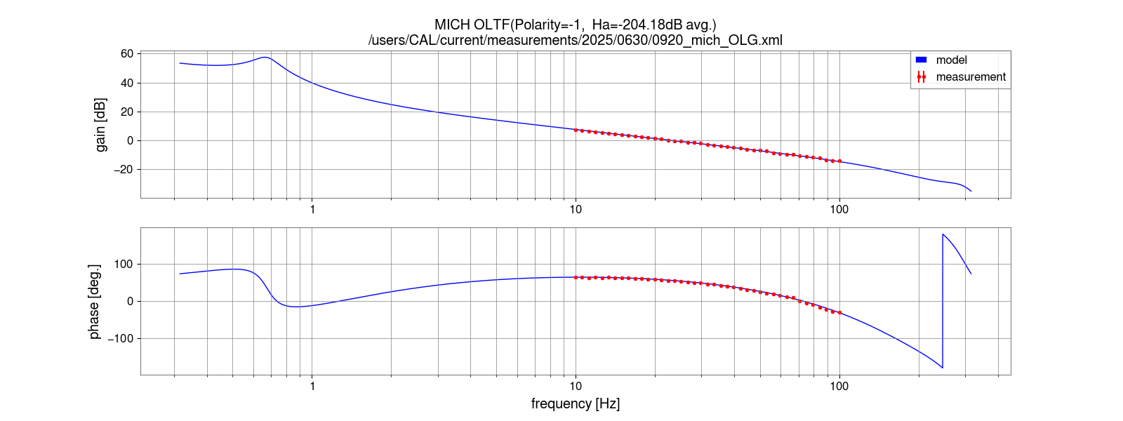
| H_mich | 1.115e+09 +/- 0.0067e+09 | N/A | -2.8% | Fig.1 |
| A_BS(0) | 6.180e-11 +/- 0.039e-13 | 6.000e-11 +/- 0.048e-11 | +0.8% (Free-swing) | Fig.2-3 (for Free-swing) |
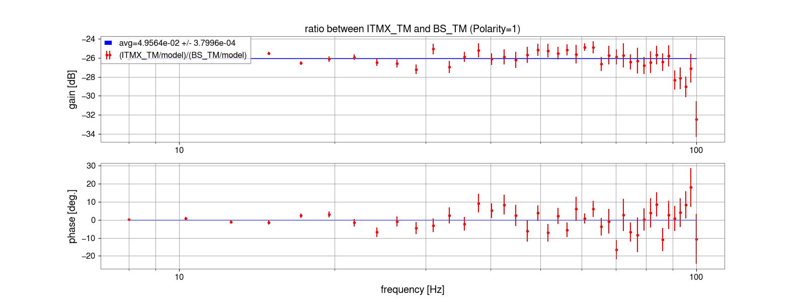
| A_ITMX(0)/A_BS(0) | 0.04956 +/- 0.00038 | same as left | -0.2% | Fig.4-5 |
| A_ITMX(0) | 3.063e-12 +/- 0.030e-12 | 3.3583e-12 +/- 0.0043e-12 | +0.7% (Free-swing) | |
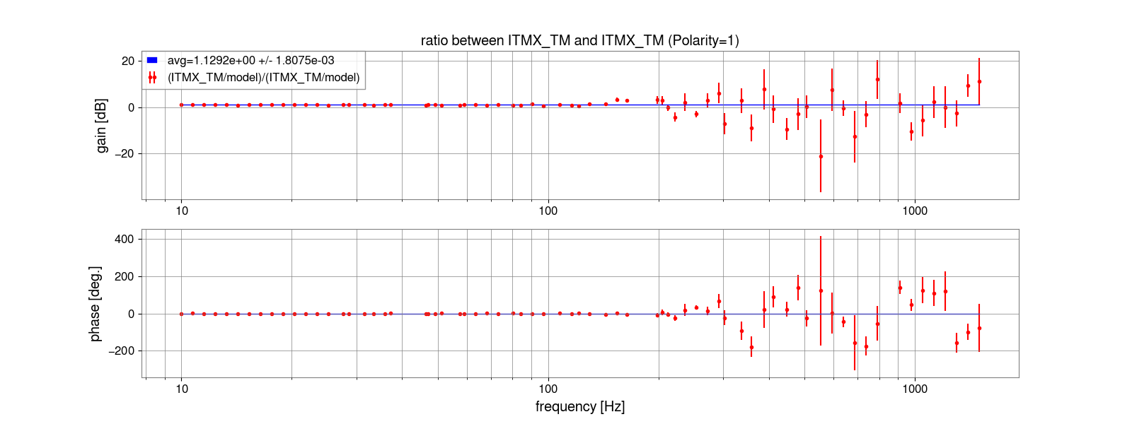
| A_ITMX(3)/A_ITMX(0) | 1.1292 +/- 0.0018 | same as left | +0.1% | Fig.6-7 |
| A_ITMX(3) | 3.459e-12 +/- 0.035e-12 | 3.3583e-12 +/- 0.0043e-12 | +0.7% (Free-swing) | |
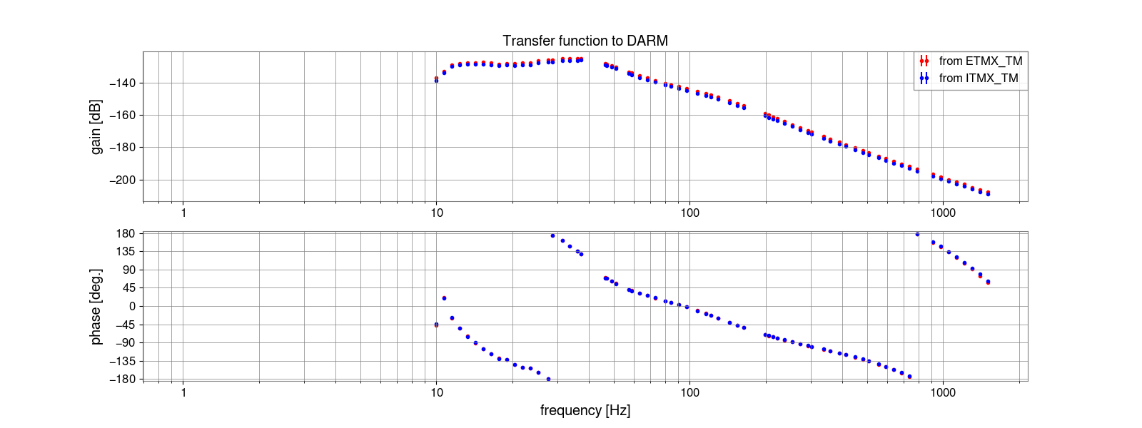
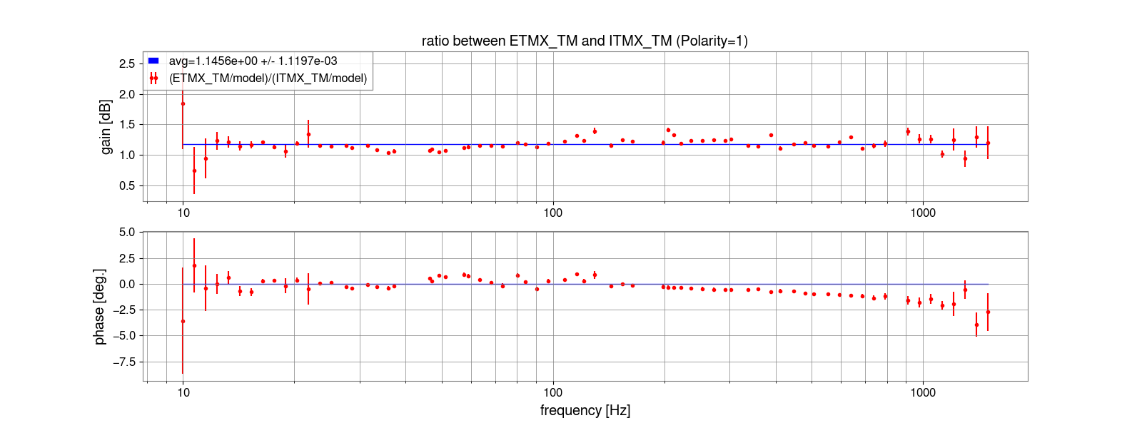
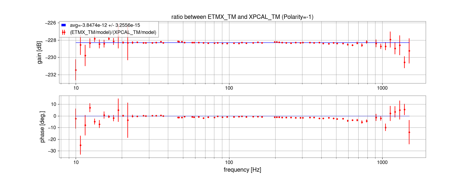
| A_ETMX_TM/A_ITMX(3) | 1.1456 +/- 0.0011 | same as left | -7.9% | Fig.8-9 |
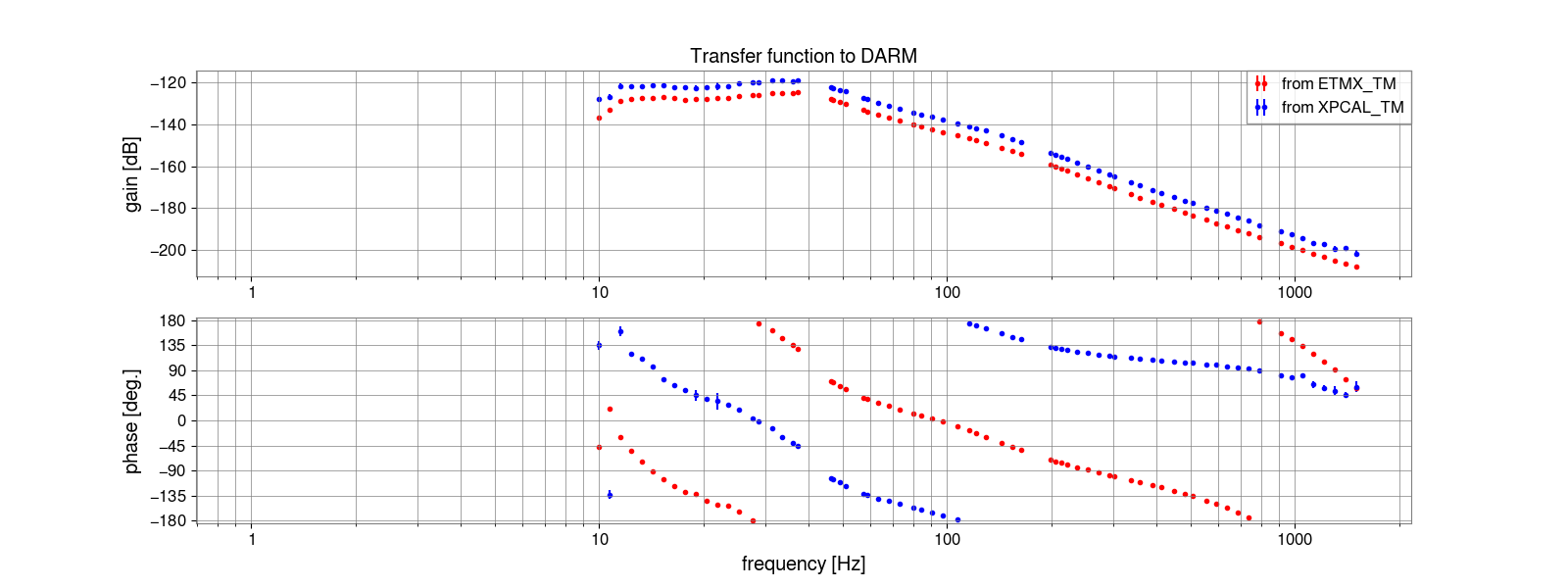
| A_ETMX_TM | 3.962e-12 +/- 0.040e-12 | 3.8574e-12 +/- 0.0033e-12 | -0.6% (XPcal) | Fig.10-11 (for XPcal) |
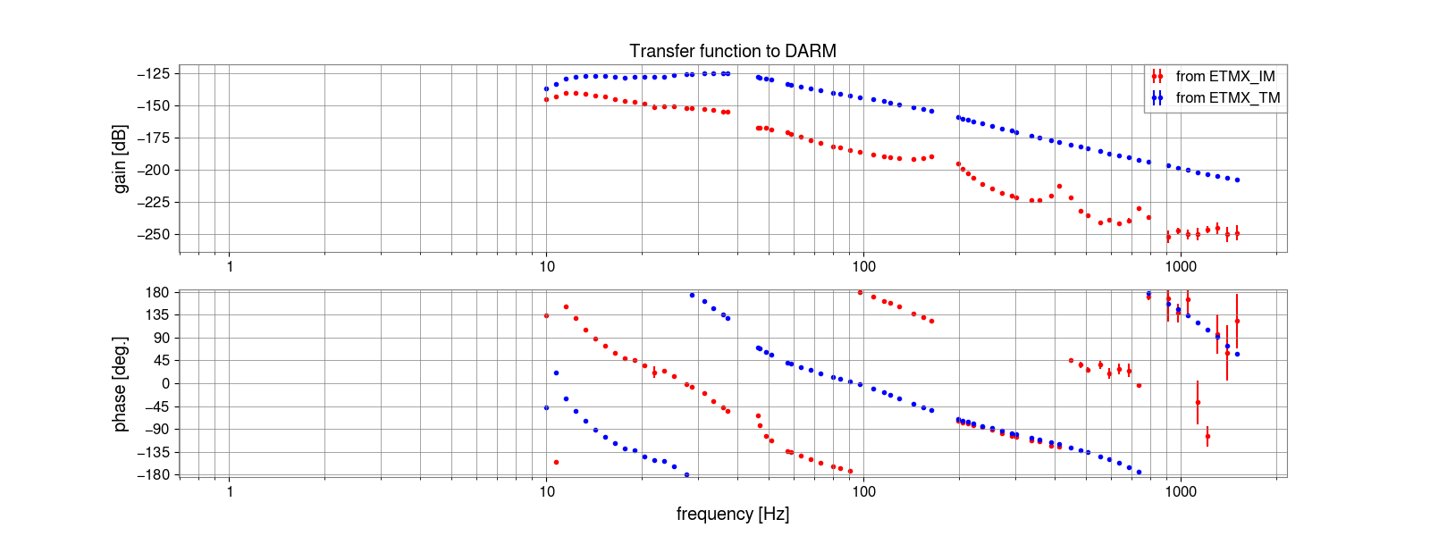
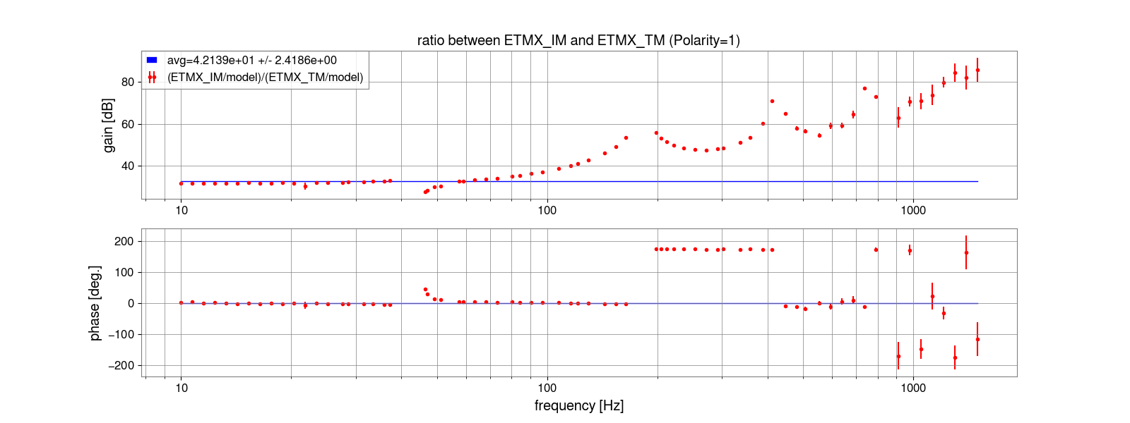
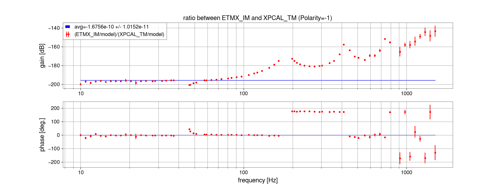
| A_ETMX_IM/A_ETMX_TM | 42.1 +/- 2.4 | N/A | -7.8% | Fig.12-13 |
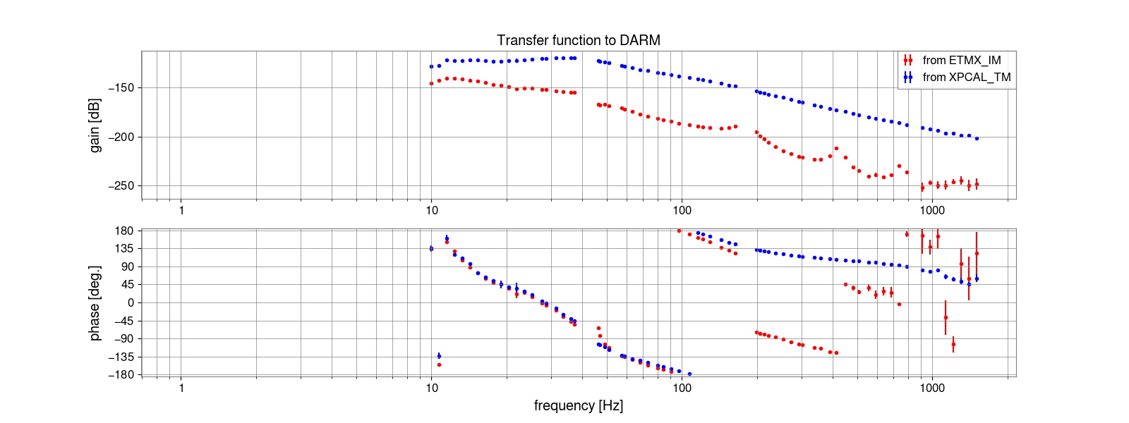
| A_ETMX_IM | 1.670e-10 +/- 0.097e-10 | 1.68e-10 +/- 0.10 | -8.7% (XPcal) | Fig.14-15 (for XPcal) |
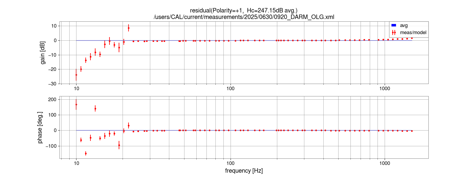
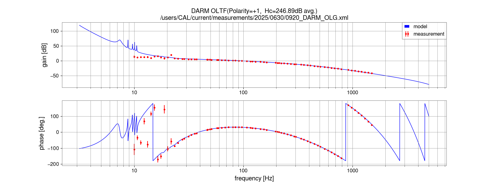
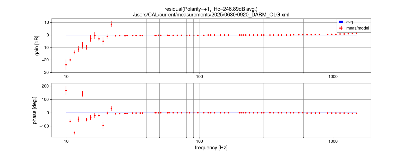
| H_DARM | 2.211e+12 +/- 0.023e+12 | 2.2775e+12 +/- 0.0071e+12 | +0.9% (XPcal) | Fig.16-19 |
| 1/H_DARM | 4.522e-13 +/- 0.048e-13 | 4.391e-13 +/- 0.014e-13 | N/A | |
| A_BS(1)/A_BS(0) | 1.0423 +/- 0.0048 | same as left | +0.5% (Free-swing) | Fig.20-21 |
| A_BS(1) | 6.441e-11 +/- 0.050e-11 | 6.254e-11 +/- 0.057e-11 | +1.3% (Free-swing) | |
| H_MICH | 4.628e+08 +/- 0.036e+08 | 4.767e+08 +/- 0.044e+08 | +9.8% (Free-swing) | Fig.22-25 |
| 1/H_MICH | 2.161e-09 +/- 0.017e-09 | 2.098e-09 +/- 0.019e-09 | N/A | |
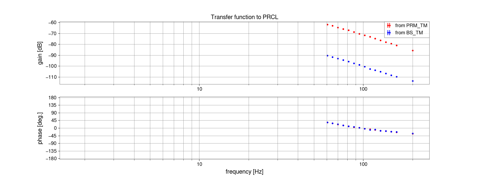
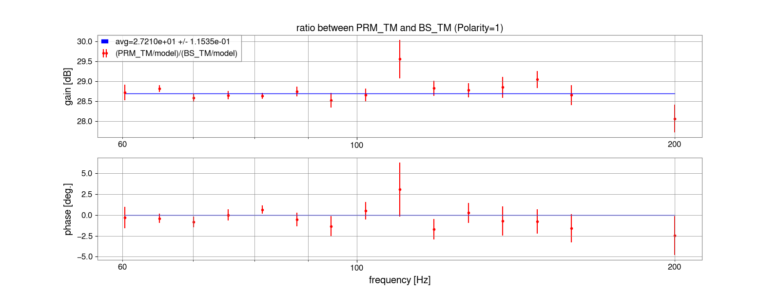
| A_PRM(1)/A_BS(1) | 27.21 +/- 0.12 | same as left | +1.0% | Fig.26-27 |
| M2P FF gain | 0.03675 +/- 0.00016 | same as left | N/A | |
| A_PRM | 8.764e-10 +/- 0.078e-10 | 8.509e-10 +/- 0.086e-10 | +2.3% (Free-swing) | |
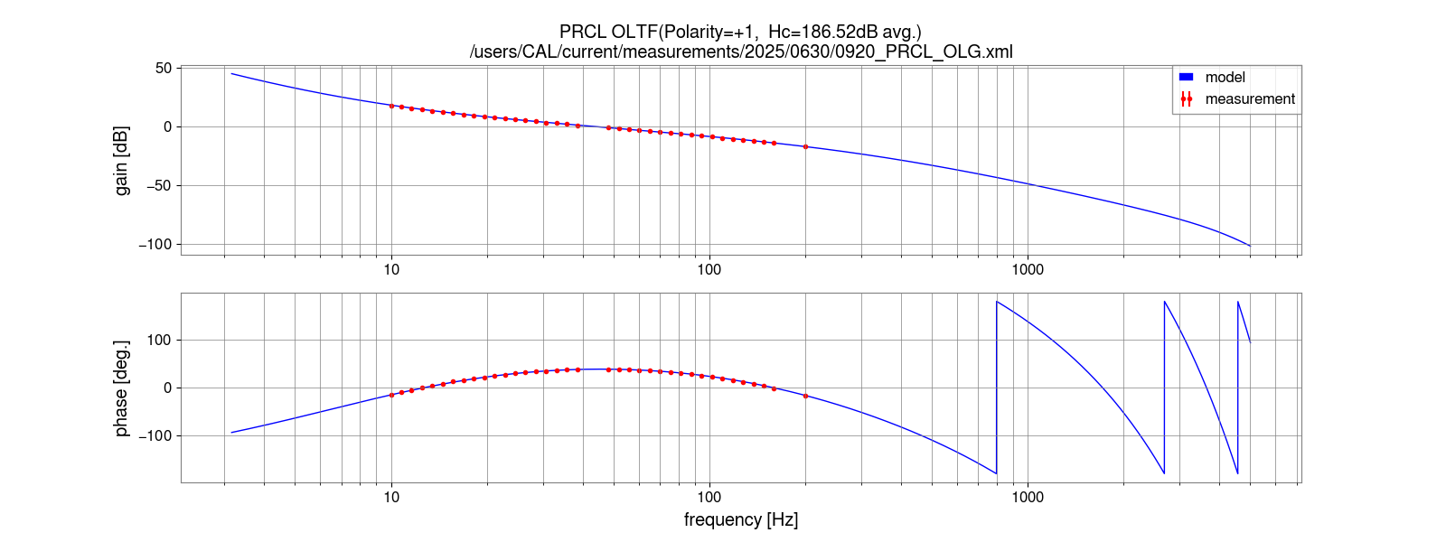
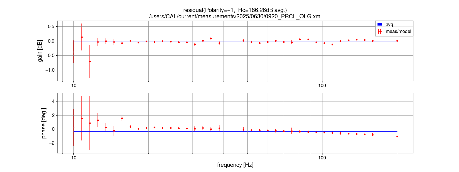
| H_PRCL | 2.057e+09 +/- 0.018e+09 | 2.118e+09 +/- 0.021e+09 | +4.3% (Free-swing) | Fig.28-31 |
| 1/H_PRCL | 4.862e-10 +/- 0.043e-10 | 4.720e-10 +/- 0.048e-10 | N/A | |
| A_ITMX(3)/A_BS(1) | 0.05369 +/- 0.00049 | same as left | N/A | |
| M2D FF gain | 18.6 +/- 3.2 | same as left | N/A |


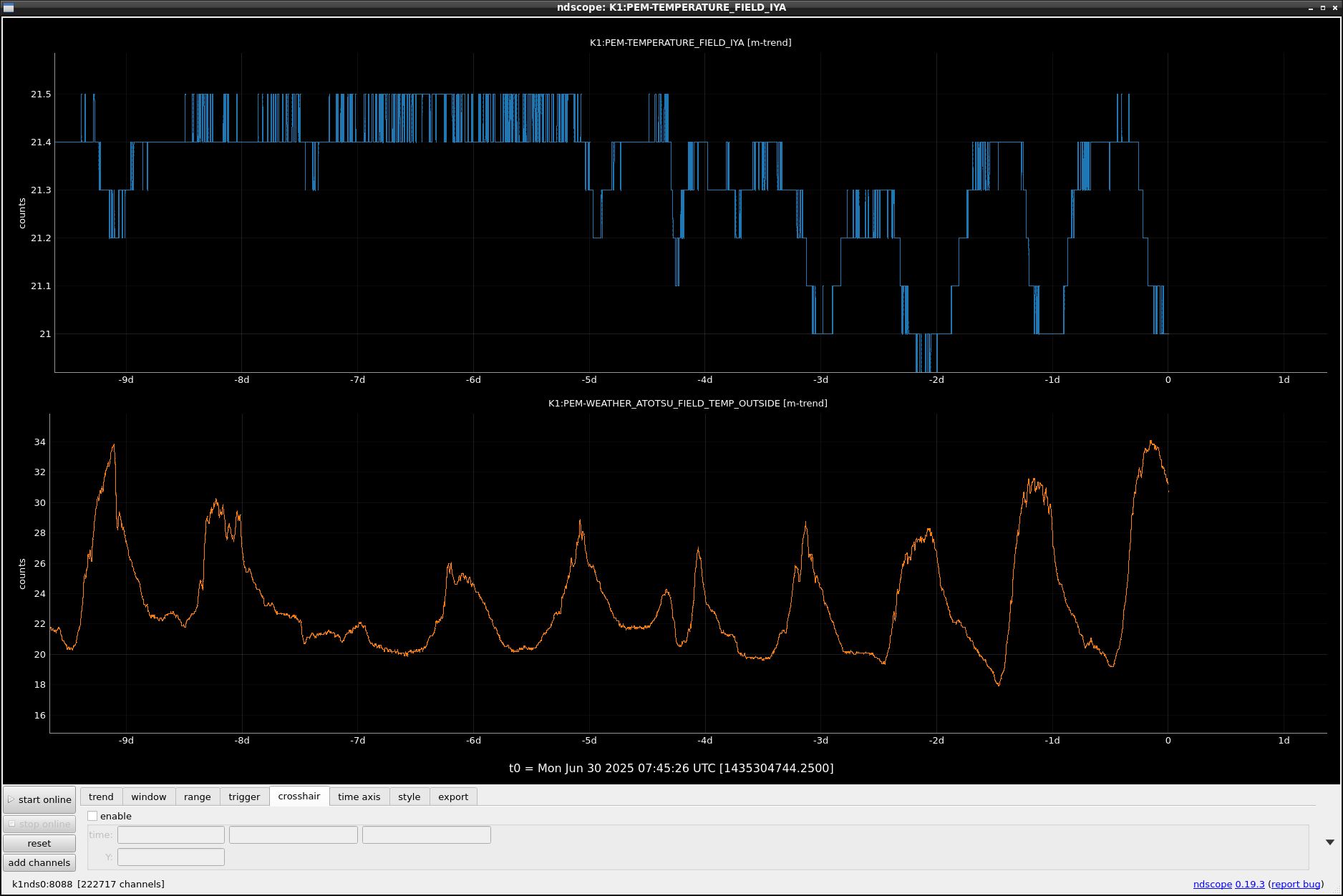
(At outside, the temperature of noon is high for the outside, but low in IYA area)
This trend continued for a long time(At least more than 100 days), but I cannot find this issue in previous klog.
Some temperature control system worked?
We accepted SDFs related to the cal measurement (klog#34412) in observation.snap, down.snap, and safe.snap (k1calcs).
K1:CAL-MEAS_{CURRENT, LATEST}

with Dan, YamaT, SawadaT
We performed full measurements for the IFO calibration.
The analysis results will be posted at a later date.
Notes:
The DARM-related measurements were conducted after adjusting the feedforward gains (see klog#34410).
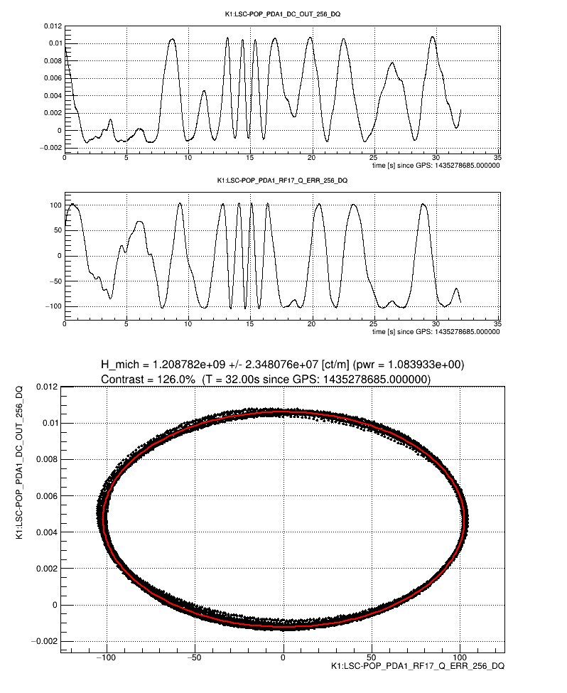
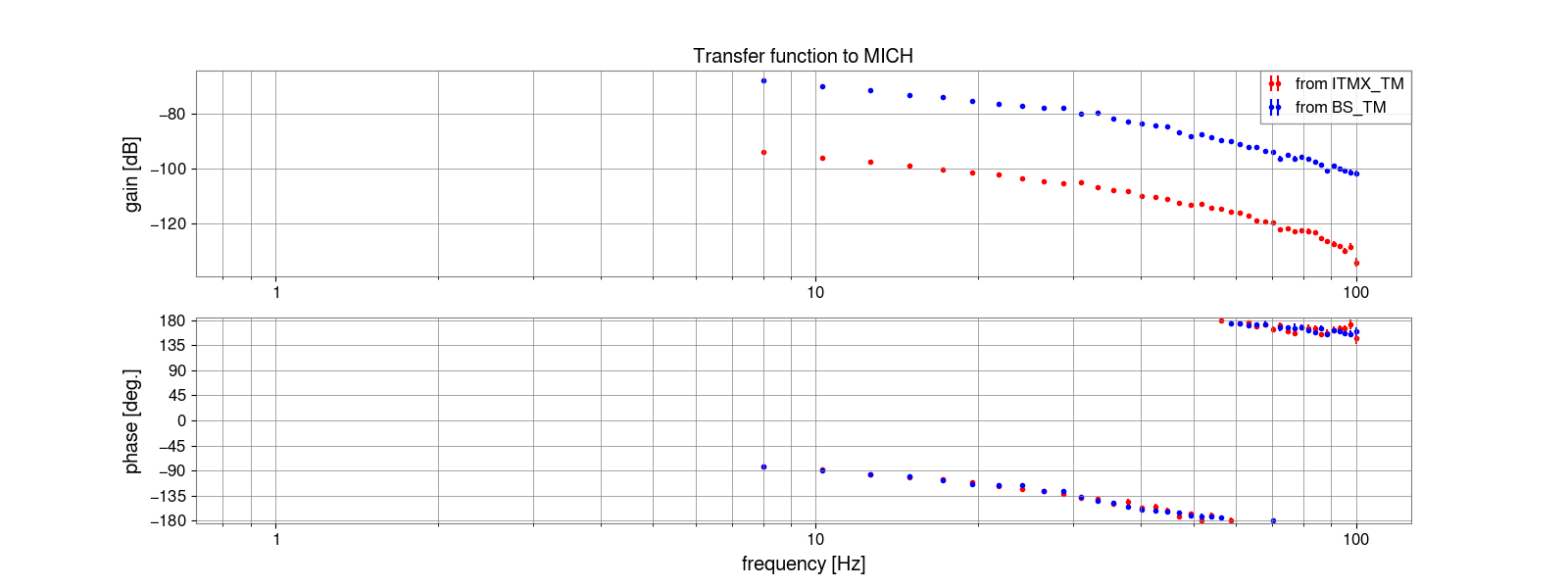
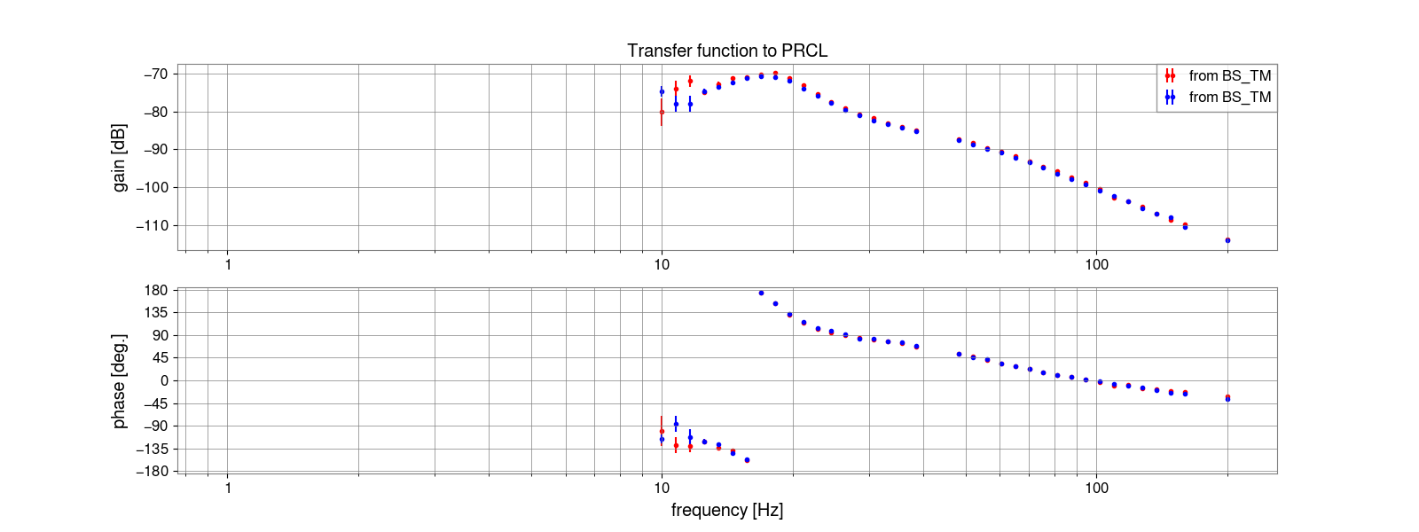
Following the same method as klog#34040 and klog#34033, we performed measurements to observe the changes in DC caused by differences in the number of whitening filter stages for ITMX-TM and BS-TM.
Measurement files (`/users/CAL/current/measurements/2025/0603/0920_*`):
0920_BS_TM_PRCL.xml : Whitening = 1 stage
0920_BS_TM_PRCL-1.xml : Whitening = 0 stage
0920_ITMX_TM_DARM_PRFPMI_WFOFF.xml : Whitening = 0 stage
0920_ITMX_TM_DARM_PRFPMI_WFON.xml : Whitening = 3 stages
- Each value is estimated based on JGW-L2314903.
- Estimated values by Pcal and Free-swing are consistent with each other at approximately 3%.
- Previous full measurement which is the reference of comparison is klog#34033.
- There is no significant change in all parameters.
- Numbers in parentheses indicate a number of engaged de-whitening filters.
- Low-frequency (<1Hz) zero/pole in disengaged de-whitening filters (see also klog#33874) are compensated based on circuit measurement only for ETMX in klog#34229 and klog#34244.
- So this effect must be considered for other suspensions.
| Free-swing | XPcal | Diff. from prev. | Figures | |
|---|---|---|---|---|
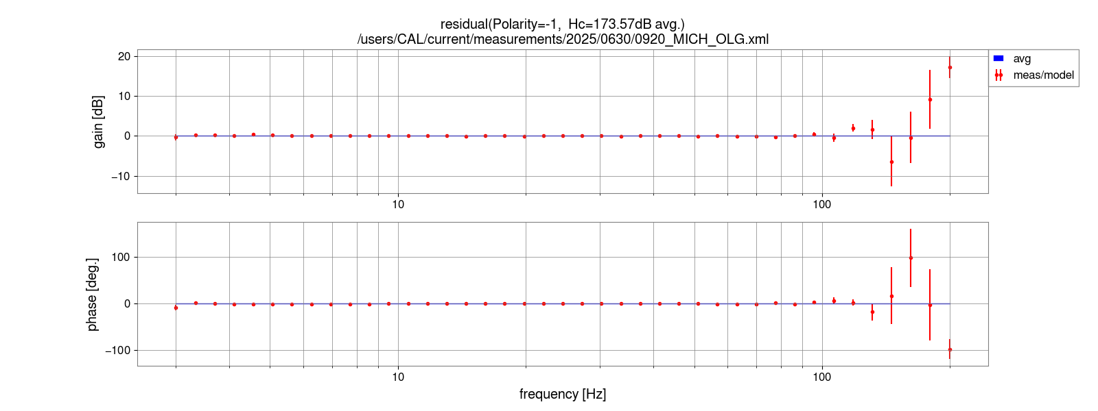
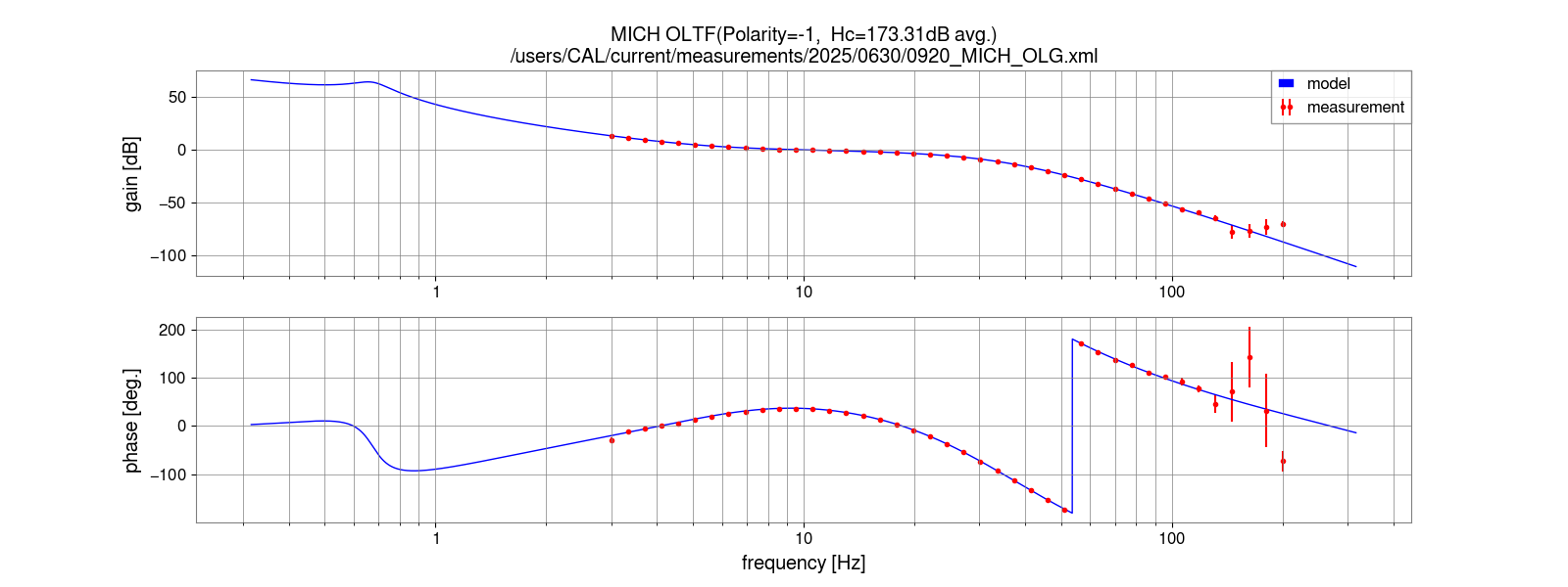
| H_mich | 1.115e+09 +/- 0.0067e+09 | N/A | -2.8% | Fig.1 |
| A_BS(0) | 6.180e-11 +/- 0.039e-13 | 6.000e-11 +/- 0.048e-11 | +0.8% (Free-swing) | Fig.2-3 (for Free-swing) |
| A_ITMX(0)/A_BS(0) | 0.04956 +/- 0.00038 | same as left | -0.2% | Fig.4-5 |
| A_ITMX(0) | 3.063e-12 +/- 0.030e-12 | 3.3583e-12 +/- 0.0043e-12 | +0.7% (Free-swing) | |
| A_ITMX(3)/A_ITMX(0) | 1.1292 +/- 0.0018 | same as left | +0.1% | Fig.6-7 |
| A_ITMX(3) | 3.459e-12 +/- 0.035e-12 | 3.3583e-12 +/- 0.0043e-12 | +0.7% (Free-swing) | |
| A_ETMX_TM/A_ITMX(3) | 1.1456 +/- 0.0011 | same as left | -7.9% | Fig.8-9 |
| A_ETMX_TM | 3.962e-12 +/- 0.040e-12 | 3.8574e-12 +/- 0.0033e-12 | -0.6% (XPcal) | Fig.10-11 (for XPcal) |
| A_ETMX_IM/A_ETMX_TM | 42.1 +/- 2.4 | N/A | -7.8% | Fig.12-13 |
| A_ETMX_IM | 1.670e-10 +/- 0.097e-10 | 1.68e-10 +/- 0.10 | -8.7% (XPcal) | Fig.14-15 (for XPcal) |
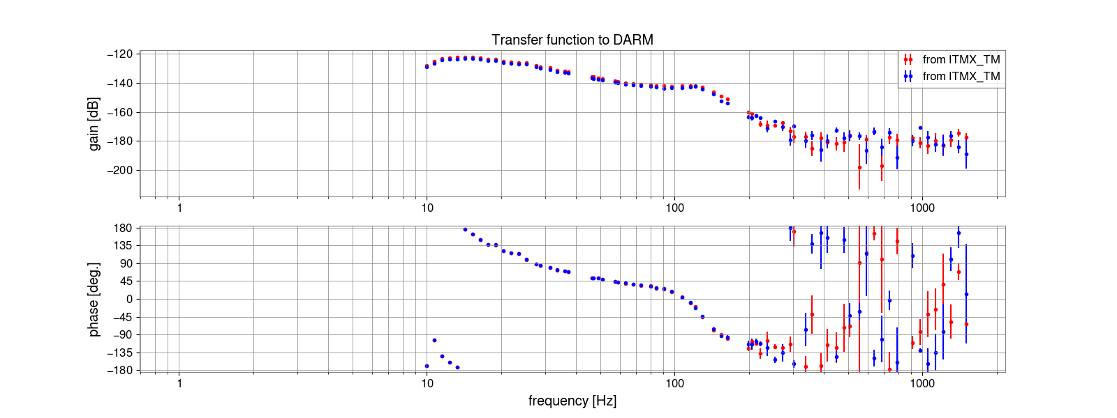
| H_DARM | 2.211e+12 +/- 0.023e+12 | 2.2775e+12 +/- 0.0071e+12 | +0.9% (XPcal) | Fig.16-19 |
| 1/H_DARM | 4.522e-13 +/- 0.048e-13 | 4.391e-13 +/- 0.014e-13 | N/A | |
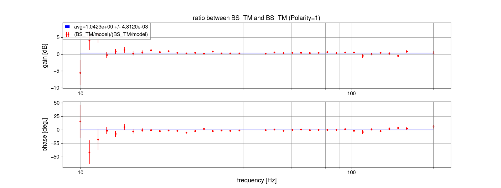
| A_BS(1)/A_BS(0) | 1.0423 +/- 0.0048 | same as left | +0.5% (Free-swing) | Fig.20-21 |
| A_BS(1) | 6.441e-11 +/- 0.050e-11 | 6.254e-11 +/- 0.057e-11 | +1.3% (Free-swing) | |
| H_MICH | 4.628e+08 +/- 0.036e+08 | 4.767e+08 +/- 0.044e+08 | +9.8% (Free-swing) | Fig.22-25 |
| 1/H_MICH | 2.161e-09 +/- 0.017e-09 | 2.098e-09 +/- 0.019e-09 | N/A | |
| A_PRM(1)/A_BS(1) | 27.21 +/- 0.12 | same as left | +1.0% | Fig.26-27 |
| M2P FF gain | 0.03675 +/- 0.00016 | same as left | N/A | |
| A_PRM | 8.764e-10 +/- 0.078e-10 | 8.509e-10 +/- 0.086e-10 | +2.3% (Free-swing) | |
| H_PRCL | 2.057e+09 +/- 0.018e+09 | 2.118e+09 +/- 0.021e+09 | +4.3% (Free-swing) | Fig.28-31 |
| 1/H_PRCL | 4.862e-10 +/- 0.043e-10 | 4.720e-10 +/- 0.048e-10 | N/A | |
| A_ITMX(3)/A_BS(1) | 0.05369 +/- 0.00049 | same as left | N/A | |
| M2D FF gain | 18.6 +/- 3.2 | same as left | N/A |
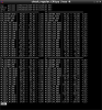
Here is a update of the 8 blasting between 2025/06/18 03:22:49 UTC and 2025/06/26 13:59:52 UTC. The plots are available at DAC wiki.
- 6 times: lockloss occurred from OBSERVATION state
- The the amplitude of the seismic motion was large enough to make the lockloss.
- Even though the bomb size was 6.2 kg (which is relatively small), the lockloss occurred. I guess this is because the blasting point is approaching to the KGRA tunnel.
- 2 times: interferometer was in down state or during lock acquisition.
Operators name: Takaaki Yokozawa, Hiroshi Takaba, Dan Chen
Shift time: 9-17 (JST)
Check Items:
- VAC: No issues were found.
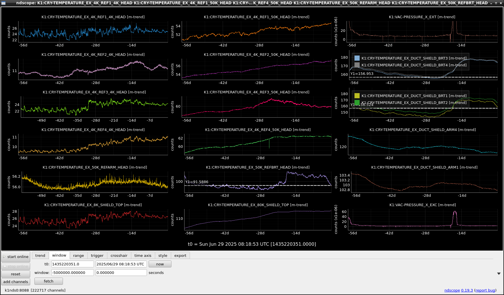
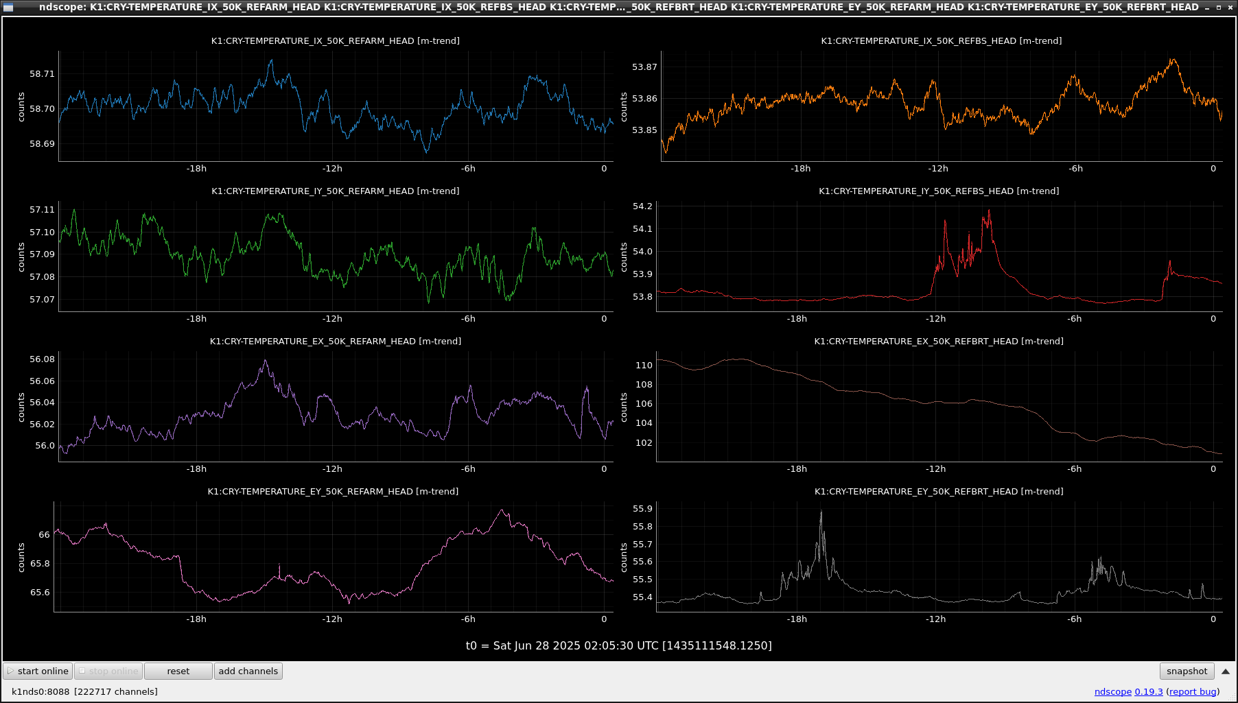
- CRY cooler: Temperature of EX 50_REFBRT went down by 6K between 6/29 16:00 and 6/30 10:00. No other movement.
- Compressor: No issues were found.
IFO was used by CAL group during the day.
After their works, the state was set to be CALIB NOT READY.
[Dan, Hido, Sawada, Yamamoto, Ushiba]
Abstract:
Gain tuning of MICH2DARM, MICH2PRCL, and PRCL2DARM FF were performed.
All update seems fine.
Detail:
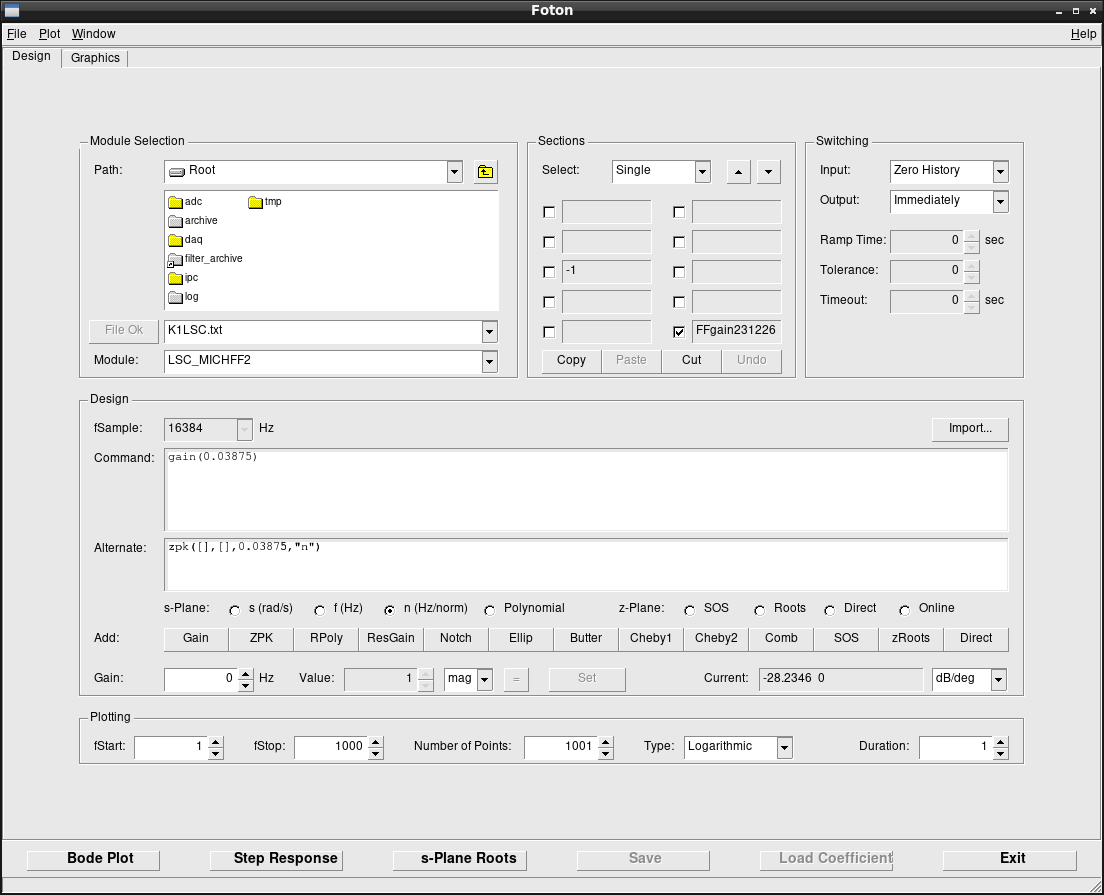
First, calibration team measured the actuator efficiency ratio of MICH2PRCL/PRM2PRCL.
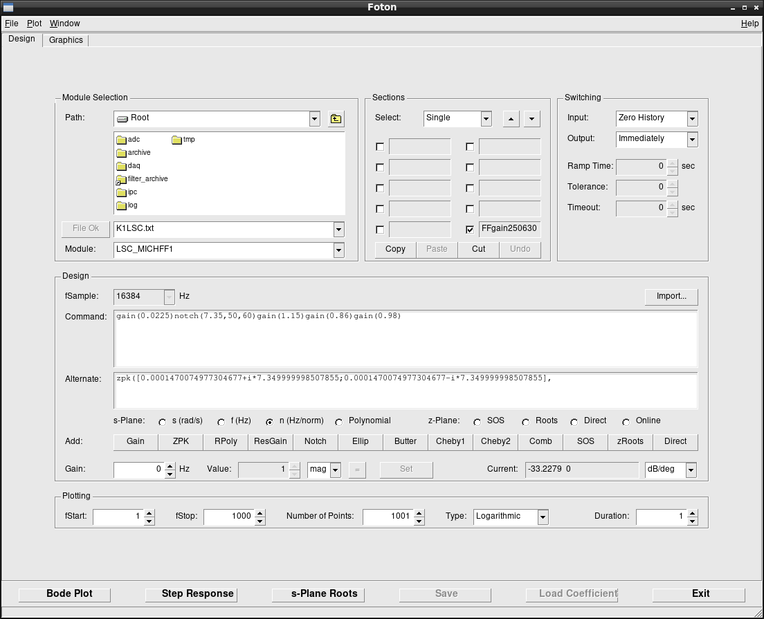
The new value was 0.03675 and FM10 of LSC_MICHFF2 filter bank was updated.
Figure 1 and 2 show the filters before and after the update, respectively.
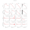
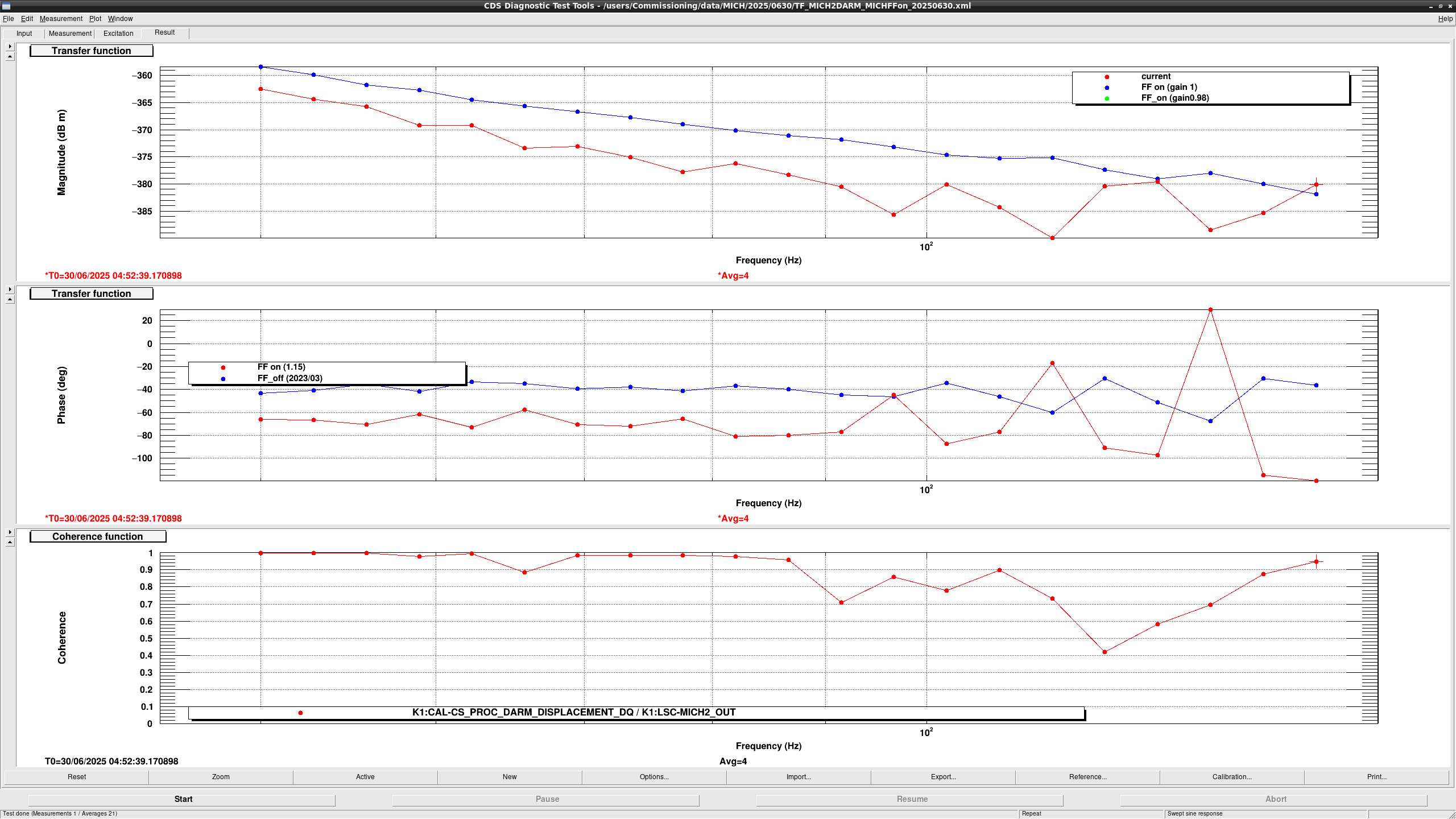
Then, I measured MICH2DARM coupling with several FF gain to tune the MICH2DARM FF gain (fig3).
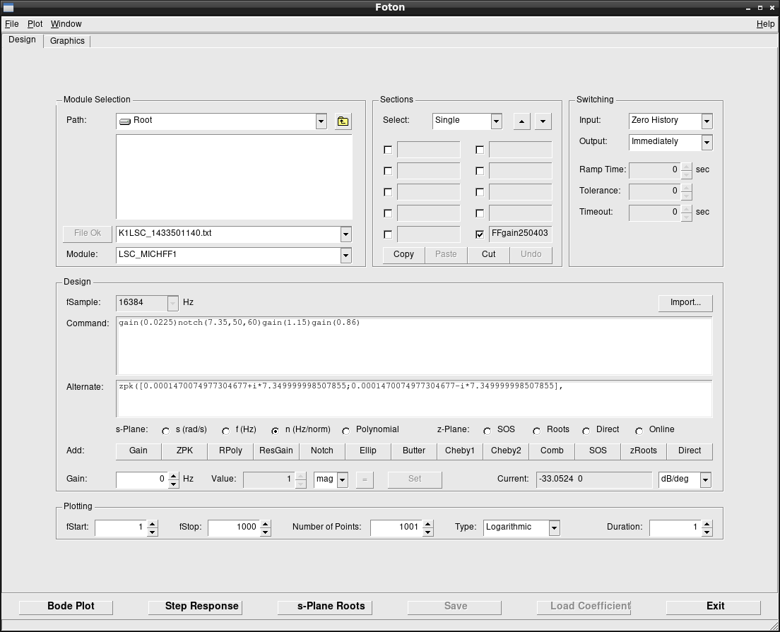
MICH FF performance seems better when MICH FF gain is 0.98, so I implemented the gain of 0.98 at FM10 of LSC_MICHFF1 filter bank.
Figure4 and 5 show the filters before and after the update, respectively
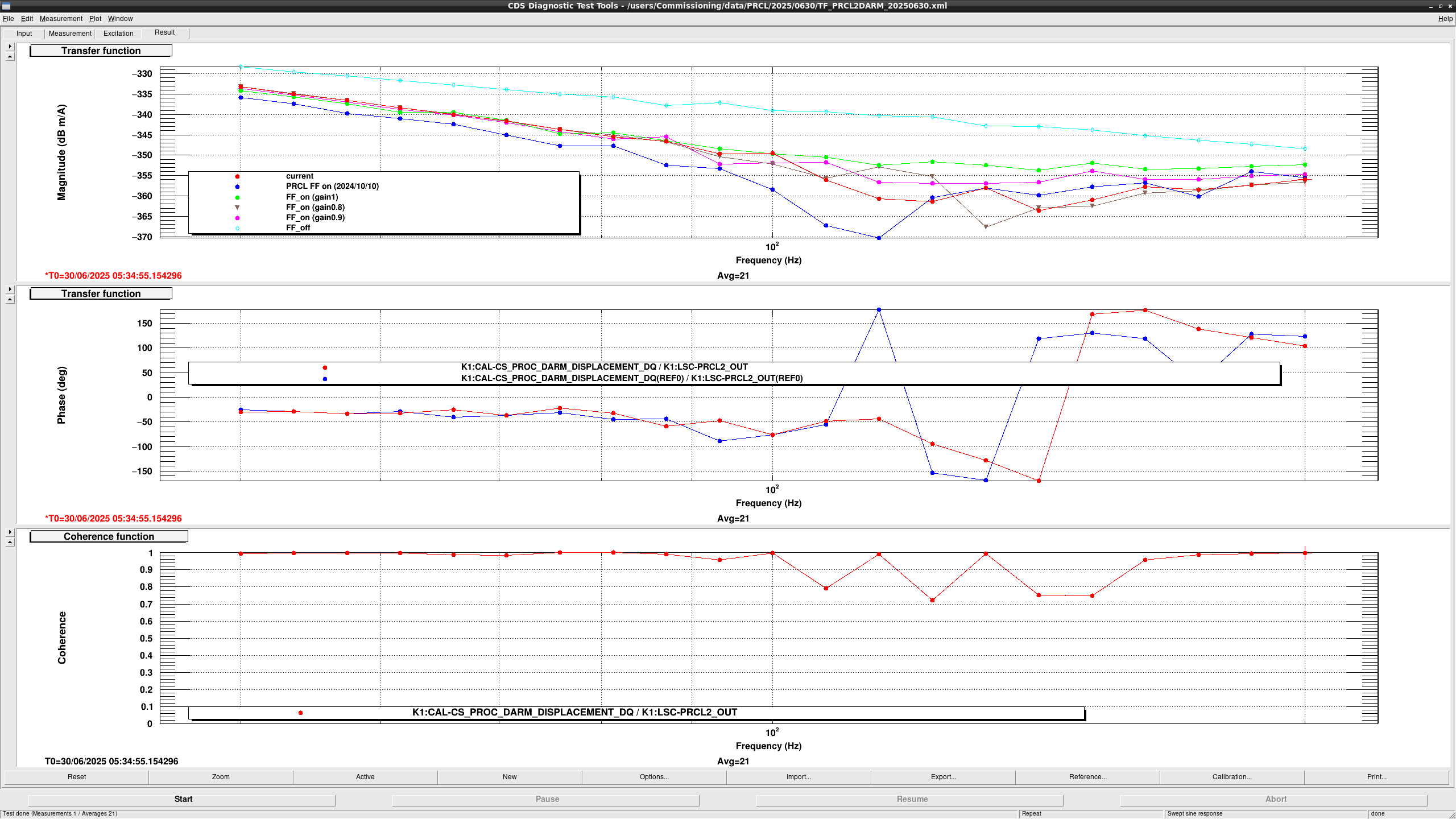
After that, I measured PRCL2DARM coupling with several FF gain (fig6).
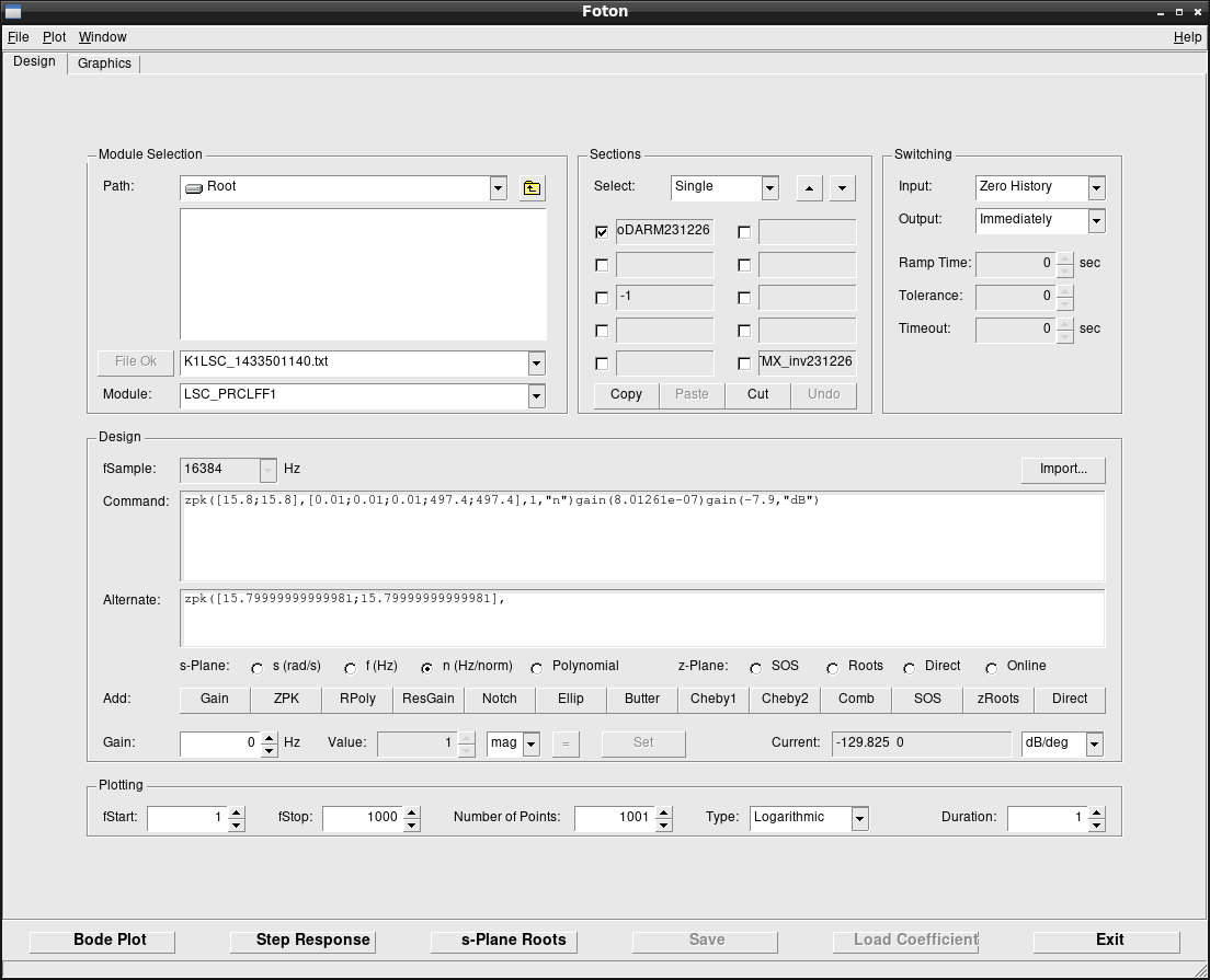
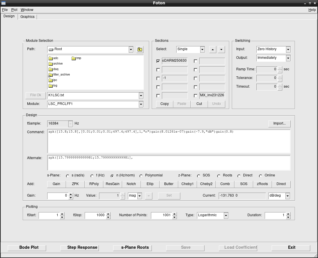
Though the low frequency performance is worse than before, the best gain seems 0.8, so I update FM1 of LSC_PRCLFF1 filter bank.
Figure 7 and 8 show the filters before and after the update, respectively.
For further tuning of PRCL2DARM FF, we may need to modify the filter shape and it takes a time, so I didn't performit today.
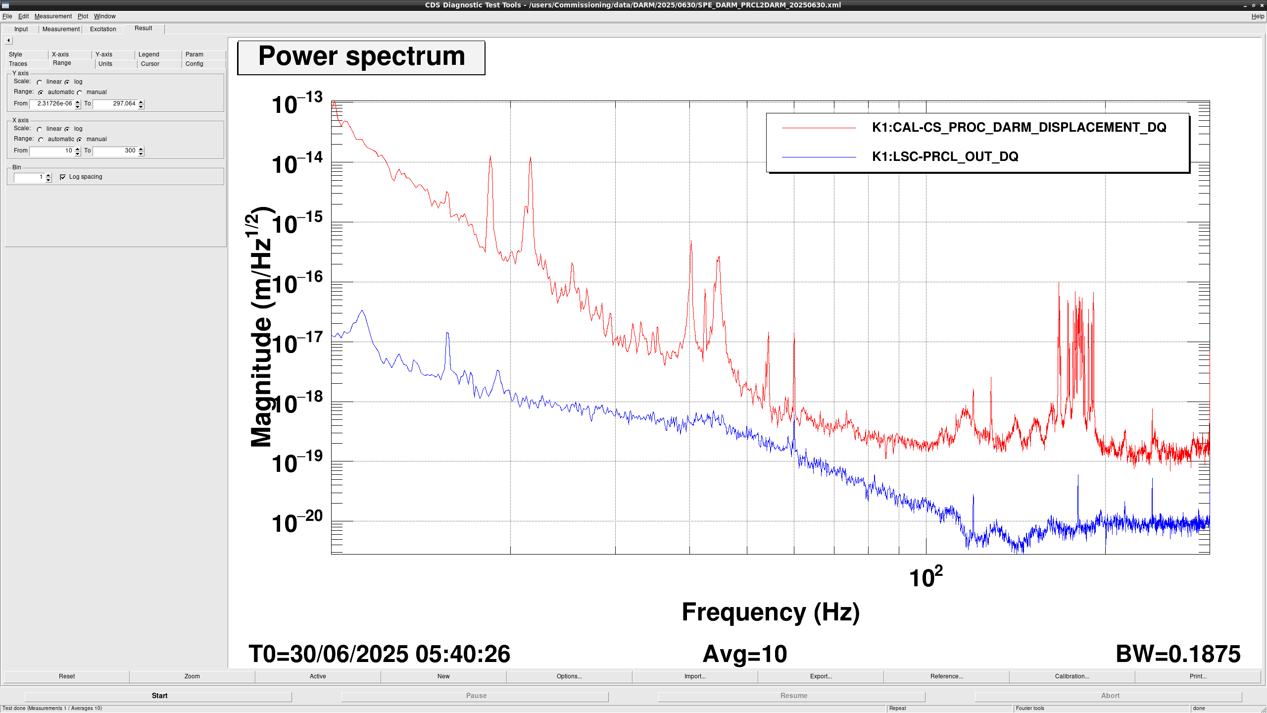
Since current PRCL2DARM noise budget cased on the today's measurement is low enough (fig9), the current situation should be fine.
Since all updates are done by overwriting current FF filters, no SDF change happens.

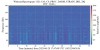
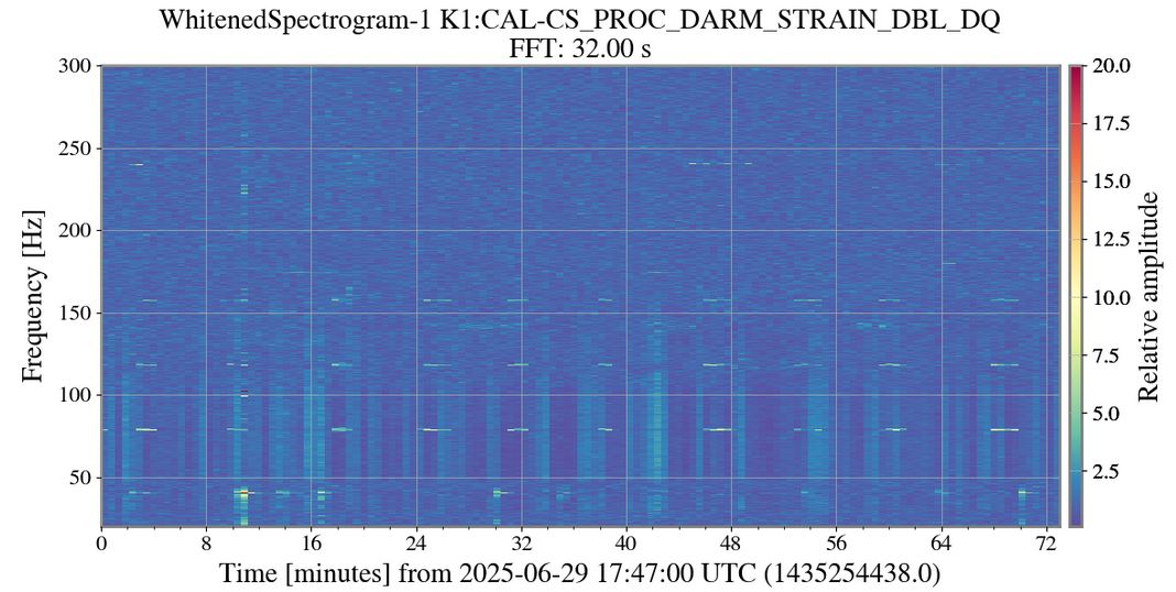
Still I cannot find the critical reason, but I found the 80 Hz peak appeared in about every 7-8 min and high frequency in 120 Hz and 160 Hz
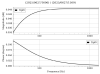
5 days have passed since the last recovery. No problem has happened until now. So, the heat up inside the 19-inch rack could be the reason.
The cryocooler 1st head temperature for the BRT side finally started decreasing as shown in Fig.1. So the temperature of BRT1,2,3,4 also started decreasing.
Operators name: Ikeda, Hirose
Shift time: 9-17 (JST)
Summary:
Check Items:
* VAC: no problem
* CRY: no problem
=> As reported in klog34404, Ikeda-san wrote a script to compare the temperature at AM10:00 with that at PM4:00 of the previous day as related to klog34401.
* TEMP: no problem
=> Data of K1:PEM-TEMPERATURE_FIELD_EXA_IR was no value.
IFO state (JST):
09:00 The shift was started. This status was OBSERVING.
10:00 LockLoss due to the earthquake
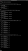
Result from check_IFO_status.py:
Large earthquake arrived within 3 hours.
Please check IFO status again after 30 minutes.
10:30 Result from check_IFO_status.py:
Large earthquake arrived within 1 hours.
Please check IFO status again after 30 minutes.
11:00 Result from check_IFO_status.py:
Large earthquake arrived within 1 hours.
Please check IFO status again after 30 minutes.
11:17 OBSERVING
11:42 LockLoss due to the earthquake
Result from check_IFO_status.py:
Large earthquake arrived within 1 hours.
Please check IFO status again after 30 minutes.
12:09 OBSERVING
16:17 LockLoss due to the earthquake
Result from check_IFO_status.py:
Large earthquake arrived within 1 hours.
Please check IFO status again after 30 minutes.
16:47 Result from check_IFO_status.py:
Large earthquake arrived within 1 hours.
Please check IFO status again after 30 minutes.
17:00 This shift was finished. The status was "LOCKING".
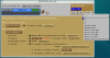
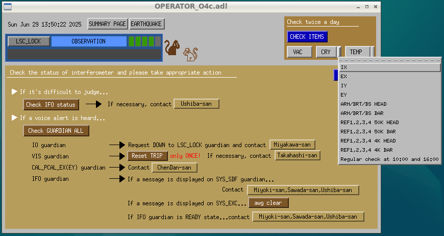
Since comparing the "cooler unit temperature changes" between 16:00 the previous day and 10:00 the current day was time-consuming, we added a script to perform the check automatically.
/users/OBS/O4c/script/check_regular_CRY.py
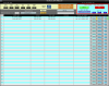
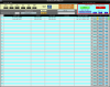
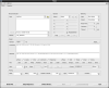
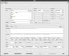
Sitemap - Commissioning Dock → OPERATOR → Beside CRY → Regular check at 10:00 and 16:00 (Fig-1)
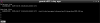
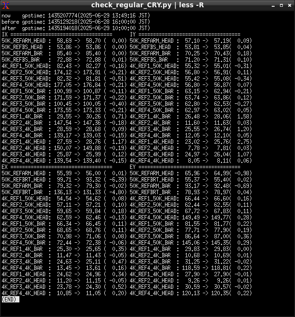
When the terminal opens, an image like Fig-2 is displayed.
The numbers in parentheses indicate the temperature change, and if the change exceeds 10 K, it is displayed in red text (this is expected behavior, though not yet confirmed).
You can open it at any time, but only the most recent data from 10:00 or 16:00 will be displayed.
Please make sure to open it after 10:00 or 16:00 when performing the check.
A reference image has been attached in the "1029 O4C Check Items during Shift" document.
Operators name: Hirose, Ikeda
Shift time: 9-17 (JST)
Summary:
Check Items:
* VAC: no problem
* CRY: no problem
=> Data from the previous day was not available, so NDSCOPE was used to research the data.
* TEMP: no problem
IFO state (JST):
09:00 LockLoss due to the earthquake
09:14 OBSERVING
11:19 LockLoss due to the earthquake
12:04 OBSERVING
15:12 LockLoss
Result from check_IFO_status.py:
IFO is stable enough (duty cycle for the past 3 hours is 98%).
Please check IFO status again after 30 minutes.
19.923444271087646
15:42 Check after 30 min.
Result from check_IFO_status.py:
IFO is stable enough (duty cycle for the past 3 hours is 83%).
Please check IFO status again after 30 minutes.
2.8863821029663086
15:44 OBSERVING
17:00 OBSERVING
Other Work
K-Log#34401
=> Added ndscope template for the purpose of checking values since the previous day's values were not captured.
Ikeda, Hirose
During the observation shift, there is a “Cryocooler Temperature Change” item in the dairycheck items.
The task is to record the temperature of the cryocooler at AM10:00 and PM4:00 during the Saturday and Sunday shifts, and to compare it at AM10:00 with the previous day's PM4:00, and at PM4:00 with the same day's AM10:00.
However, in the case of the AM10:00 check on Saturday, we need to compare the temperature of the cryocooler unit with the temperature at PM4:00 on Friday.
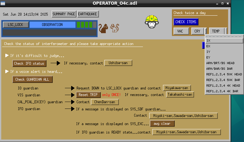
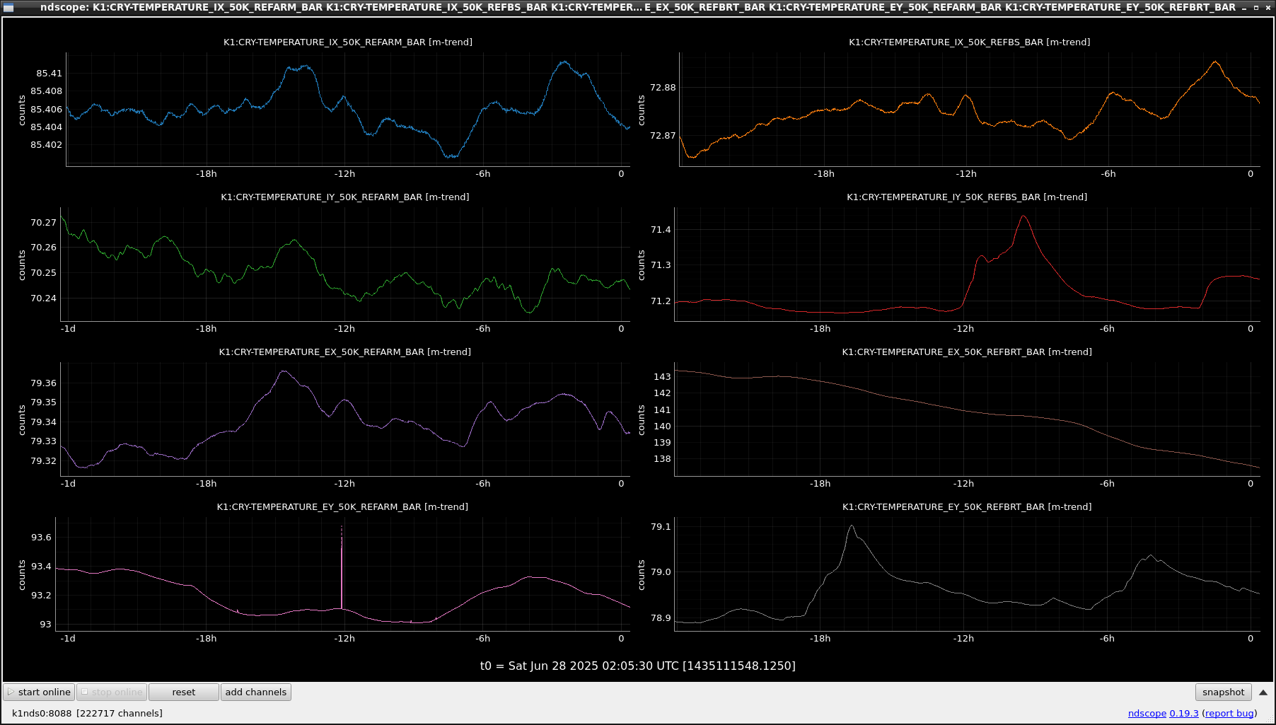
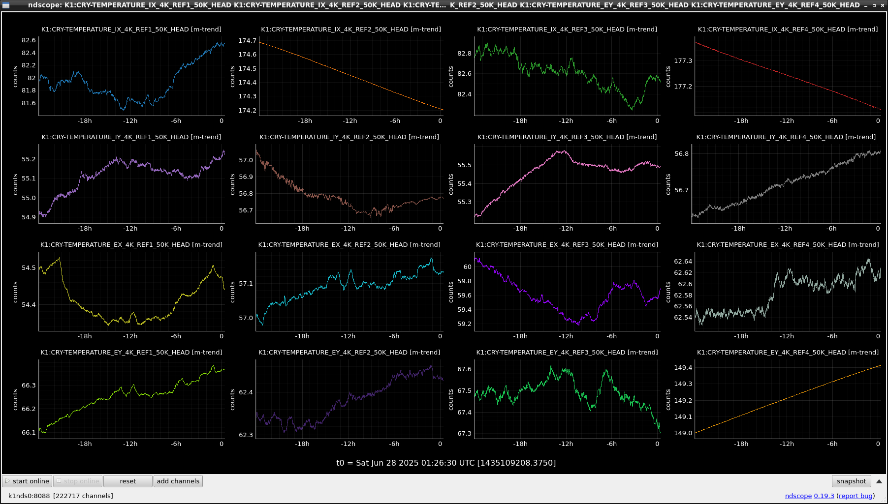
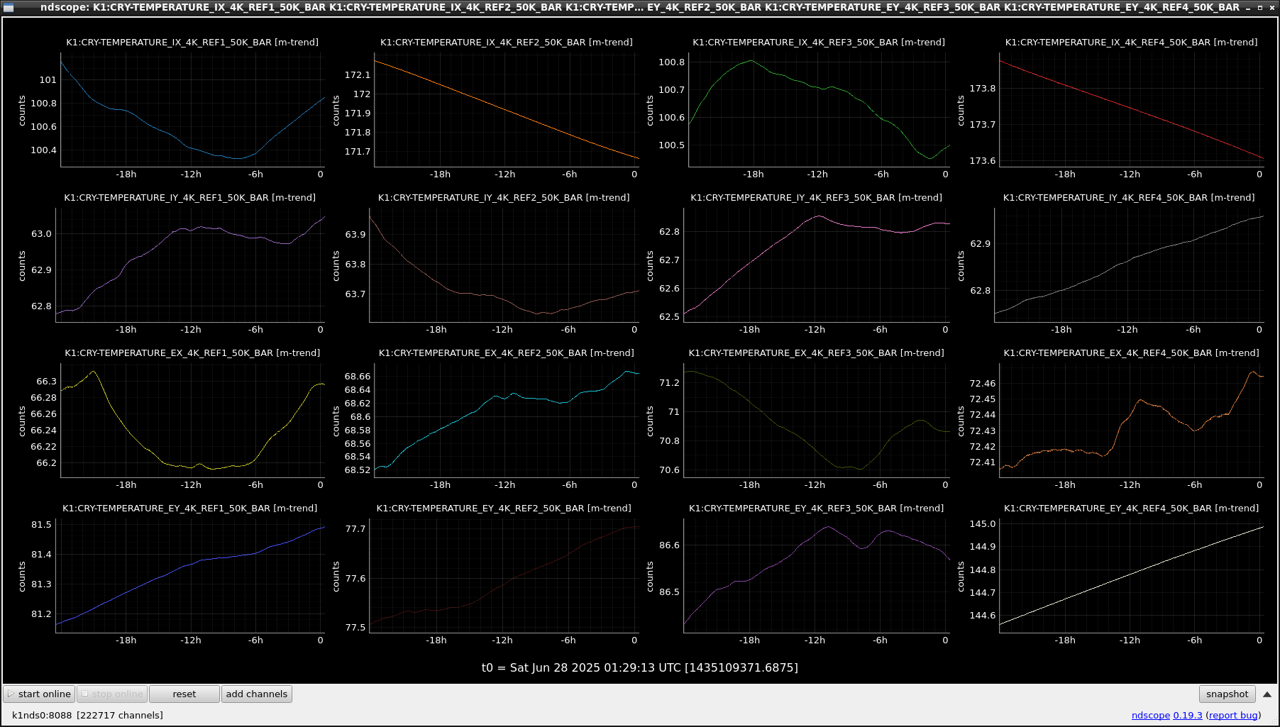
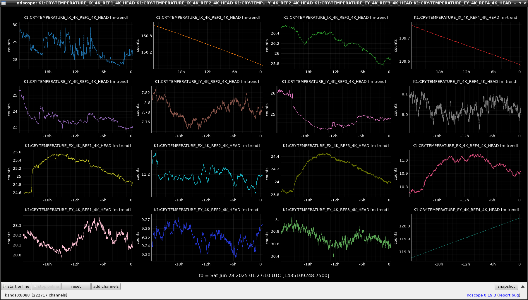
We created ndscope templates to see the temperature changes of cryocoolers and set it to medmscreen.(FIG1)
OPERATOR_O4c.adl->the side part of "CRY"->"ARM/BRT/BS HEAD(FIG2)", "ARM/BRT/BS BAR(FIG3)", "REF1,2,3,4 50K HEAD(FIG4)", "REF1,2,3,4 50K BAR(FIG5)", "REF1,2,3,4 4K HEAD(FIG6)", "REF1,2,3,4 4K BAR(FIG7)"

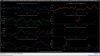
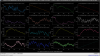
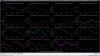
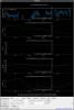
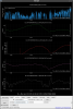
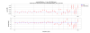
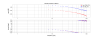
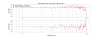
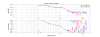
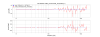
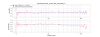
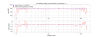
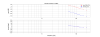
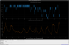
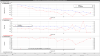
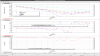
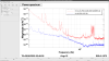
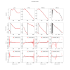
Fig.1. showed the spectrum and coherence between PDA3 RF45 I
(Blue) 2025/06/28 00:21:00 6.2 Mpc
(Red) 2025/06/28 01:55:00 7.0 Mpc
As you can see, some unknown 140 Hz peak disappeared, and several coherence was detected in CARM out-of-loop PD.
So, If noise subtraction to this data was performed, we expect to subtract a lot.
/data/LVK/low-latency/ll_merged/K1_NoGap/K-K1_llhoftNoGap-########-###.gwf
are set to split files if there are missing frames, and to generate files at 4096 seconds if there are no missing frames.
Also,
/data/LVK/low-latency/ll_merged/K1/K-K1_llhoftNoGap-########-4096.gwf
is keeping to store data as before.
Therefore, the file will be duplicated, but I will leave the previous one for a while someone may be using it.
Time stamp of the visitors(27+2 pepole) who entered center preroom and xarm.
(Monitored with Ikeda-san.)
15:00? center preroom
15:22 center parking area
15:24 Xarm in
15:30 Xarm out
15:30 out of mine
15:40 Mine shutter closed
We turned ON the OBS INTENT flag around 18:49 JST, June 27, 2025 after the approval of Ushiba-san.
CAL group
We did the calibration measurements.
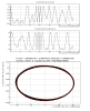
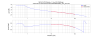
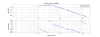
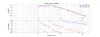
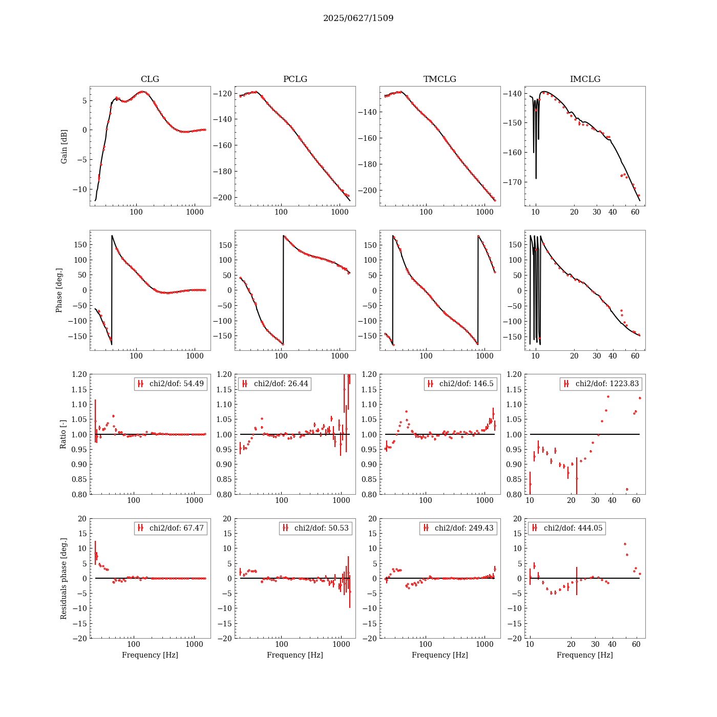
Estimated parameters taken while visitors were present are as follows.
H_etmxtm = 3.850142293e-14 @10Hz ( 0.52% from previous measurements)
H_etmxim = 1.621508136e-14 @10Hz ( 3.2% from previous measurements)
Optical_gain = 2.126800024e12 ( 0.63% from previous measurements)
Cavity_pole = 18.183601559 Hz ( -0.16% from previous measurements)
Previous values are listed in klog#34310.
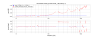
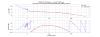
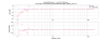
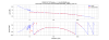
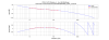
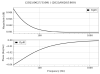
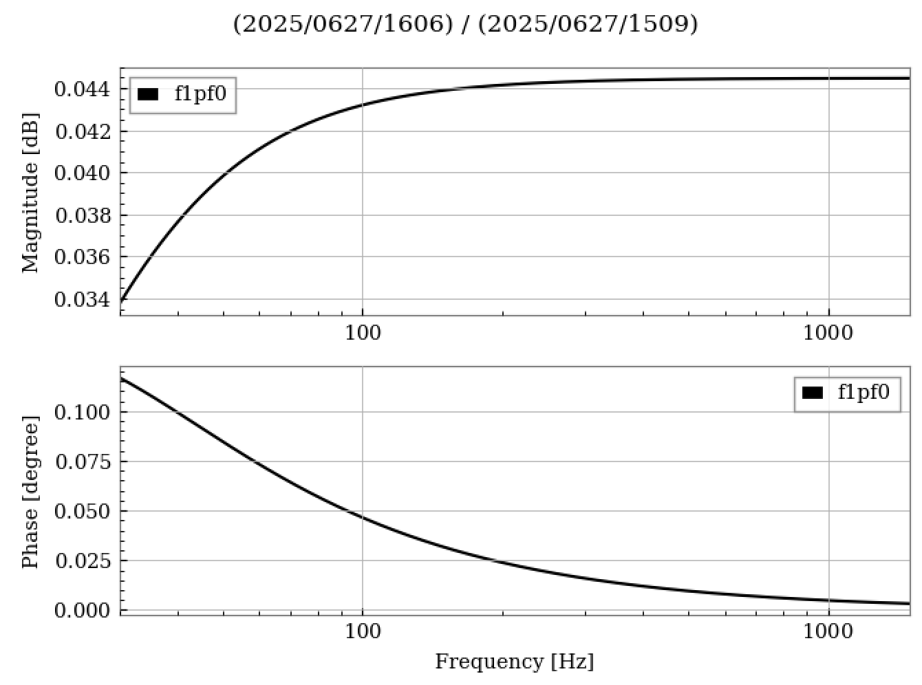
Fig. 2 and Fig.4 shows the ratio of the sensing functions estimated.
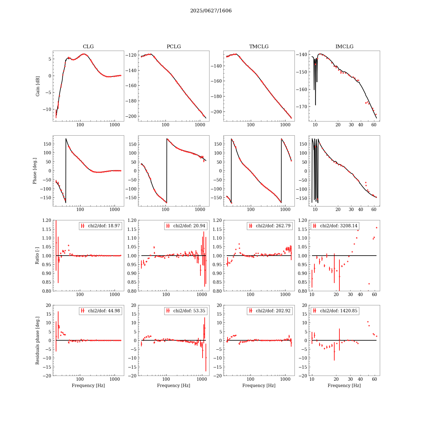
Post-tour measurement results (inside the mine) are as follows.
H_etmxtm = -3.830386471e-14 @10Hz ( -0.51% from above measurements)
H_etmxim = -1.565605347e-14 @10Hz ( -3.44% from above measurements)
Optical_gain = 2.127919074e12 ( 0.05% from above measurements)
Cavity_pole = 18.267333924 Hz ( 0.46% from above measurements)
All detected changes are coming from the planned commissioning activities.
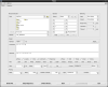
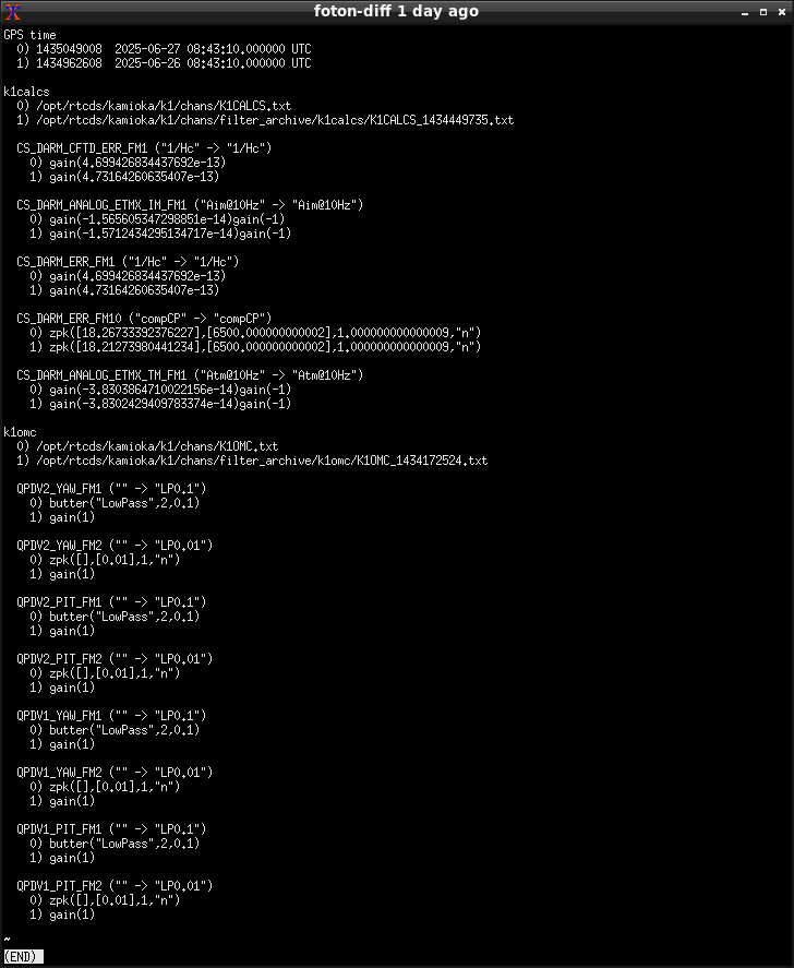
- Changes in foton Fig.1 are related to klog#34393 (k1calcs) and klog#34386 (k1omc).
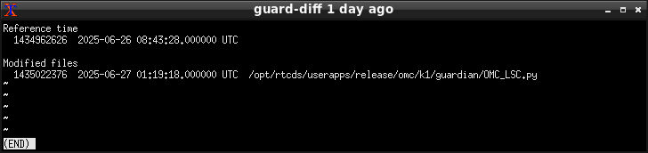
- Changes in guardian (Fig.2) are related to klog#34386 (k1omc).
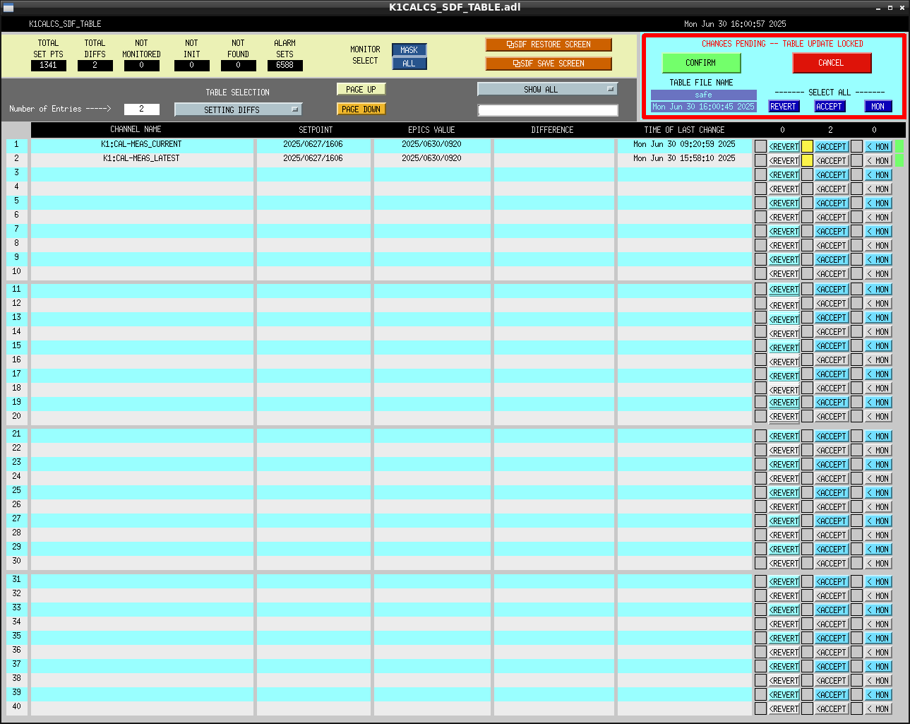
- Changes in SDF tables shown in Fig.3 are related to klog#34393 (k1calcs), klog#34386 (k1omc), and klog#34391 (k1calex, k1caley).
- No changes in the model (Fig.4).
As a result of our discussion in the CAL group, we decided not to update the line tracking parameters this time.
This line tracking is for online use only and does not affect the LL.
Finally, I raised CFC_LACTCH and IFO guardian moved from CALIB_NOT_READY to READY.

The parameters were updated based on the results from `0627/1606`.
From the current results, it is assumed that the influence of visitors is minimal (at least, no variations larger than the weekly fluctuations were observed).
Time stamp of the visitors(27+2 pepole) who entered center preroom and xarm.
(Monitored with Ikeda-san.)
15:00? center preroom
15:22 center parking area
15:24 Xarm in
15:30 Xarm out
15:30 out of mine
15:40 Mine shutter closed
The parameters were updated based on the results from `0627/1606`.
From the current results, it is assumed that the influence of visitors is minimal (at least, no variations larger than the weekly fluctuations were observed).
All detected changes are coming from the planned commissioning activities.
- Changes in foton Fig.1 are related to klog#34393 (k1calcs) and klog#34386 (k1omc).
- Changes in guardian (Fig.2) are related to klog#34386 (k1omc).
- Changes in SDF tables shown in Fig.3 are related to klog#34393 (k1calcs), klog#34386 (k1omc), and klog#34391 (k1calex, k1caley).
- No changes in the model (Fig.4).
As a result of our discussion in the CAL group, we decided not to update the line tracking parameters this time.
This line tracking is for online use only and does not affect the LL.
Finally, I raised CFC_LACTCH and IFO guardian moved from CALIB_NOT_READY to READY.

