Reports 1-1 of 1 Clear search Modify search
IOO (OMC)
yoichi.aso - 21:53 Monday 10 July 2023 (25932) Print this report
OMC DCPD circuit noise

Yokozawa, Aso

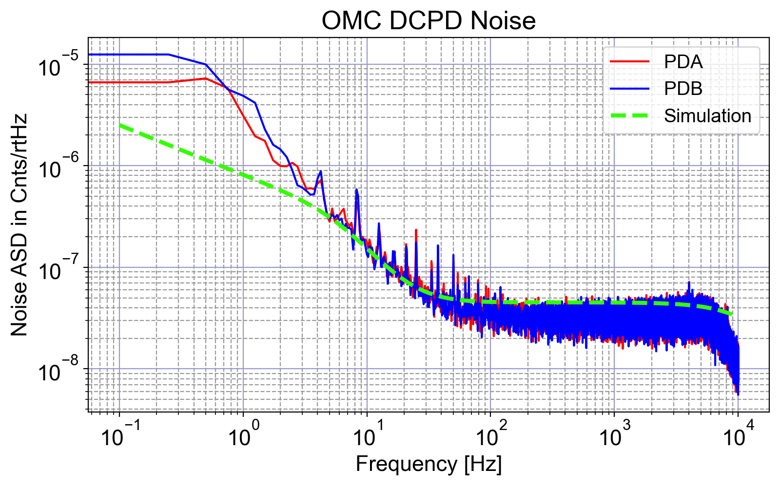
We measured the circuit noise of the OMC DCPDs by disconnecting the PDs from the transimpedance amplifiers.
To do so, we removed the D-Sub connector from the PDs to the DCPD pod.

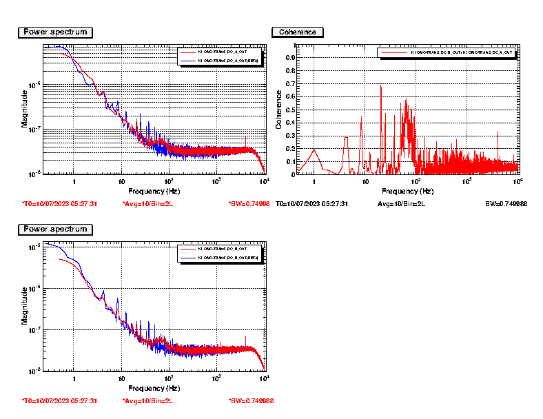
The plot below shows the measured DCPD circuit noises along with the noise prediction from a circuit simulation.

The measured noise is consistent with the circuit simulation.
The circuit simulation files can be found here.

Then we found that the noise level breathes around 100Hz as shown below.


When the noise bump appears around 100Hz, the two PDs have some coherence.


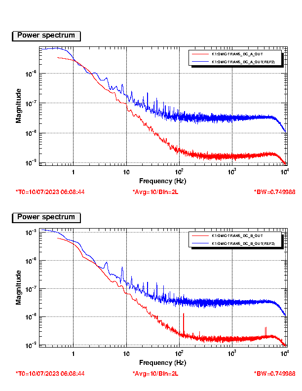
We then disconnected the DCPD circuit from the whitening filter and grounded the inputs to the whitening filter.
As shown below, the noise was reduced by an order of magnitude.
We also did not see any noise bump around 100Hz even if we waited for 10-20min.


Images attached to this report
Comments to this report:
takaaki.yokozawa - 8:40 Tuesday 11 July 2023 (25941) Print this report
I checked the correlation between 100 Hz bump and some PEM channels.
Around the noon time, as reported in klog25932, DCPDs were disconnected from circuit.

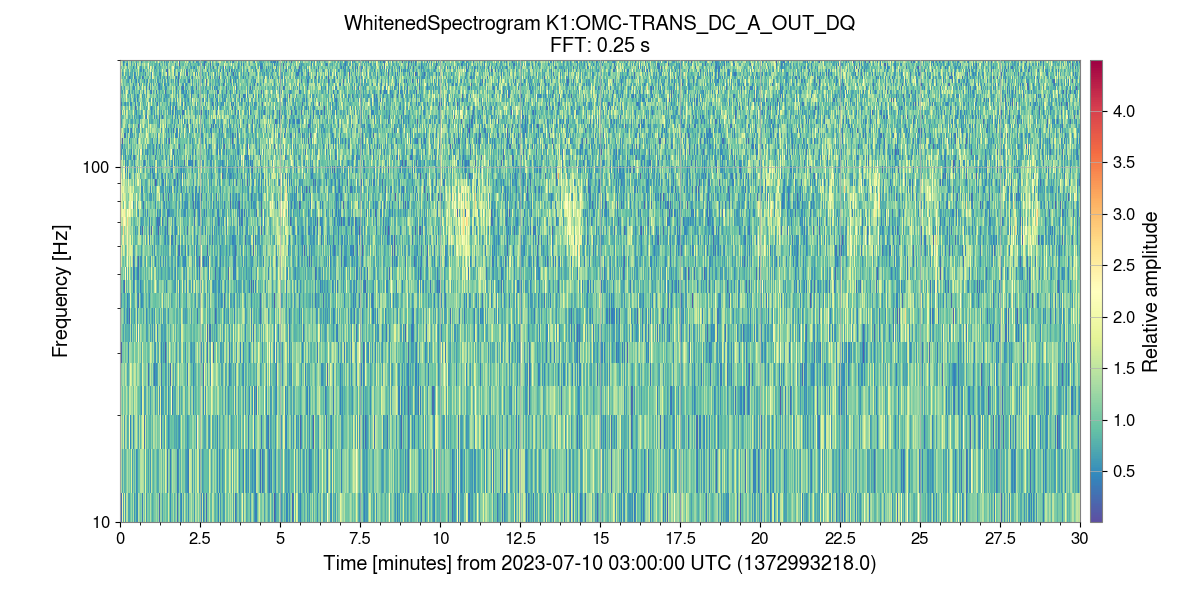
Fig.1. OMC DC PD A (20 min whitened spectrogram)
As you can see, there are four(?) glitches in 20 min

Fig.2. Voltage monitor at OMC chamber
There are some glitches, but just a chance coincidence? (Frequency is also different)

Fig.3 Voltage monitor at AS table
Similar situation from voltage monitor at OMC chamber

I also checked the microphone, accelerometer and seismometer, but no significant glitch detected.
 
Images attached to this comment
yoichi.aso - 18:42 Tuesday 11 July 2023 (25949) Print this report

I continued the investigation into this noise.

Short Cable Test
We took out the DCPD pod, containing the transimpedance amps, from the OMC chamber and put it near the OMC rack. Then connected it to the DCPD driver with a short D-Sub cable of 3m or so.
As shown in the attachment, there is no bump and I did not see any breathing behavior.
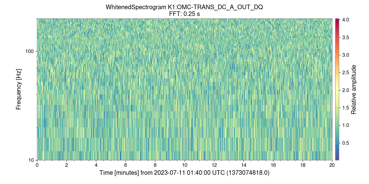
The whitened spectrogram also shows this. When the pod was in chamber, you can see sporadic noise increase near 100Hz.

When the pod is outside of the chamber, we don't see any such bump.

Long cable test

We replaced the cable to a long one (50m long) to see if there is any change.
There was no change in the noise level. Moreover, the 4Hz harmonics disappered when the pod was taken out of the vacuum.
50m cable spectra

PD connected

Then we put the DCPD pod back to the chamber and connected the PDs.
As the measured spectra show, the noise bump around 100Hz is much larger and broader.
It also breathes and never completely goes away. Also the 4Hz harmonics is clearly visible.

Oscilloscope observation of the signal

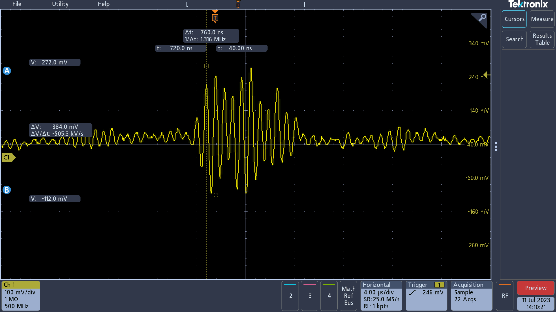
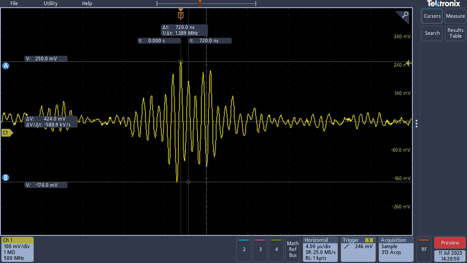
I connected an oscilloscope to directly observe the signal from the DCPD circuit to check if there is any high frequency oscillation or not.
The connection scheme was basically the same as this. I used an oscilloscope instead of the FFT analyzer or Moku. The gain of the SR560 was set to 100.

In this measurement, the DCPD pod was put back into the chamber. I compared the configurations with PD connected and disconnected.

I found 1.3MHz short oscillations. This oscillation exists both with and without PD.

With PD

Without PD

Since the size of the 100Hz bump is largely different with and without the PDs, this oscillation does not seem to be the cause of the bump.
Note that there is a gain of 100 in this measurement. The amplitude of the oscillation is a few mV rather than a few hundred mV.

Discussion

The fact that the bump disappeared when put outside of the chamber precludes the power supply as the cause of the bump.
The oscilloscope observation suggests that down conversion from high frequency noise is unlikely.
At this moment, the most likely cause of the problem is the electro-magnetic interference, probably caused by the fluctuation of the electric potential of the chamber.
We should test this hypothesis using an antenna and taking a correlation with the PD noise and the chamber voltage.

Images attached to this comment
Non-image files attached to this comment
yoichi.aso - 23:02 Wednesday 12 July 2023 (25965) Print this report

Akutsu, Yokozawa, Washimi, Tomaru, Takahashi, Aso

We have identified the source of the DCPD excess noise.
It was the cables outside of the chamber.

Cabling diagram for the OMC DCPD.

Bypassing the vacuum feedthrough flange

Routed a D-Sub cable from the DCPD driver on the rack directly to the DCPD pod without going through the feedthrough flange. Then we found that the DCPD noise was reduced drastically.

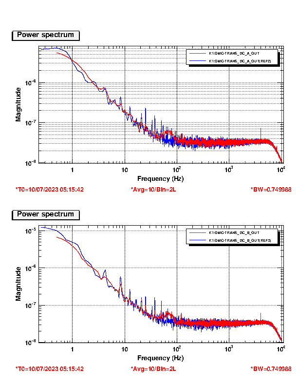
This is the original DCPD noise spectra.
This is when the feedthrough flange was bypassed.
Note that the 4Hz harmonics are gone. There is no coherence between the PDA and PDB.

Using the feedthrough but with a shorter cable

We then reverted the cabling configuration to use the feedthrough flange, but changed the D-sub cable connecting between the DCPD driver and the feedthrough from the one going around the ceiling of the clean booth to a shorter cable laid on the floor.

The noise spectrum looks like this.
The noise is still much lower than the original one. However, 4Hz harmonics are back. The floor noise is slightly higher than the reference.

Removing the ZSW connection

In order to remove the 4Hz harmonics and the residual floor noise, we disconnected the D-Sub cable connecting the BIO Converter and the feedthrough flange for ZSW.
Then we were able to remove the above excess noises as shown here.

The ZSW path is a problematic one because only the signal is provided from the BIO. The ground is provided from the DCPD driver. However, these two circuits are installed on different racks. The signal and GND goes through mostly different paths until they are conbined just before the DCPD pod. This will create a large ground loop.

In this test, the cable between the DCPD driver and the feedthrough was a short cable not going around the ceiling of the booth.

Reverting to the original D-Sub

 With the ZSW removed, we reverted the cable between the DCPD driver and the feedthrough to the original cable going around the ceiling.

The noise spectrum looks like this.
Even with the ZSW removed, the noise is stll bad. Maybe this cable is damaged?

Changing the cable to a newly installed one

In order to see if the original cable was damaged or not, we switched the cable to the one newly installed for the OMC geophones.
This cable also goes around the ceiling of the cleanbooth.

There result is this.
The noise is clearly bad.

Discussion

The lowest noise was achieved when the cable from the DCPD driver to the feedthrough goes on the floor rather than going around the ceiling. Removing the ZSW path is necessary to remove the 4Hz harmonics. 

It seems the D-Sub cable going around the ceiling receives a lot of noise, probably from the other cables going together. It could also get noise from the FFUs or LED light. We need to consider how to route the cable for sensitive signals, because laying cables on the floor is also not a good idea.

To solve the problem of the ZSW path, we should convine the ZSW signal and other DCPD signals into a single D-Sub. This should be possible by changing the GND pin from 9 to 5 and using 9 for ZSW. In addition to this, we probably need to connect the GND of the DCPD driver and the BIO converter. However, this could create another ground loop because those circuits are on different racks.

All the above measures can be done outside of the vacuum chamber. Therefore, we don't need to delay the vacuum pump down of the OMC chamber.
Non-image files attached to this comment
Search Help
×

Warning

×