Ushiba, YamaT, Akutsu (remote): following 23900 and 23901.
Abstract
Run bruco to get some hints on how to reduce features around 100-300 Hz in the sensitivity. Our first step would be to deal with CARM. Beam jitter treatment at the input optics and stray-light treatment around REFL should follow.
Inspecting channels having high coherence
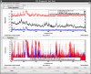
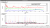
The 100-300 Hz range seems to be critical for reaching 1 Mpc. So we wanted to reduce the spectral features here first. Bruco results suggested CARM as the first suspect. For example,
LSC-REFL_PDA1_RF45_I_OUT_DQLSC-CARM_SERVO_{FAST,SLOW}_DAQ_OUT_DQLSC-MCL_OUT_DQ
had high coherence. In addition, beam jitter monitoring/control channels
IMC-IMMT1_TRANS_QPDA{1,2}_DC_PIT_OUT_DQPSL-PZT2_PIT_SUM_OUT_DQ
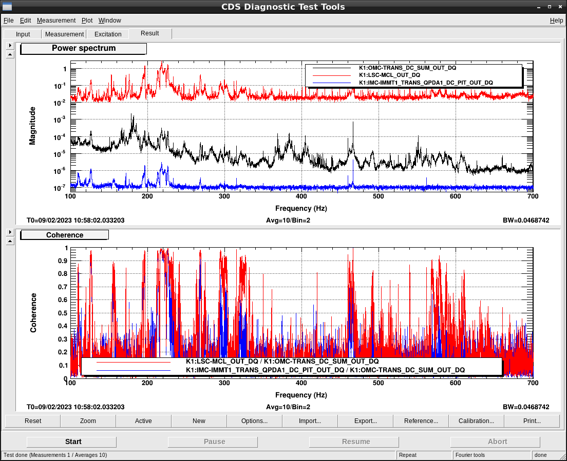
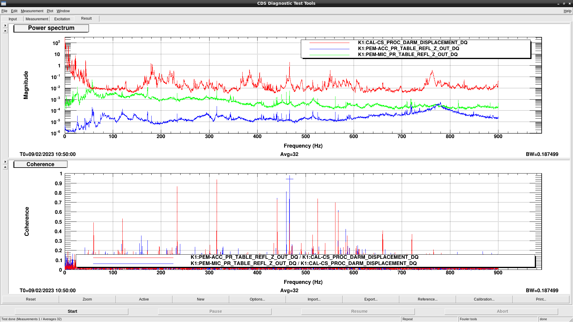
showed also high coherence. For example see Fig. 1.
Hypotheses and tests
Hypothesis 1: frequency noise would be converted to the beam jitter through MCL feed around. To test this hypothesis, we set a notch filter for CARM MCL path at around 220 Hz to see whether the spectral feature here would disappear or not. Unfortunately, no effect. The feature remained not only in DARM but also beam jitter channels such as IMC-IMMT1_TRANS_QPDA1_DC_PIT_OUT_DQ. So this beam jitter would be there without being induced via the path: CARM MCL to IMC pitch (L2P coupling). When IFI pick off monitor is completed, we may be able to obtain additional clue.
Hypothesis 2: the beam jitter would be induced due to IMC ASC. To test this hypothesis, we simply turned off IMC ASC, but no effects.
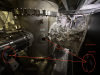
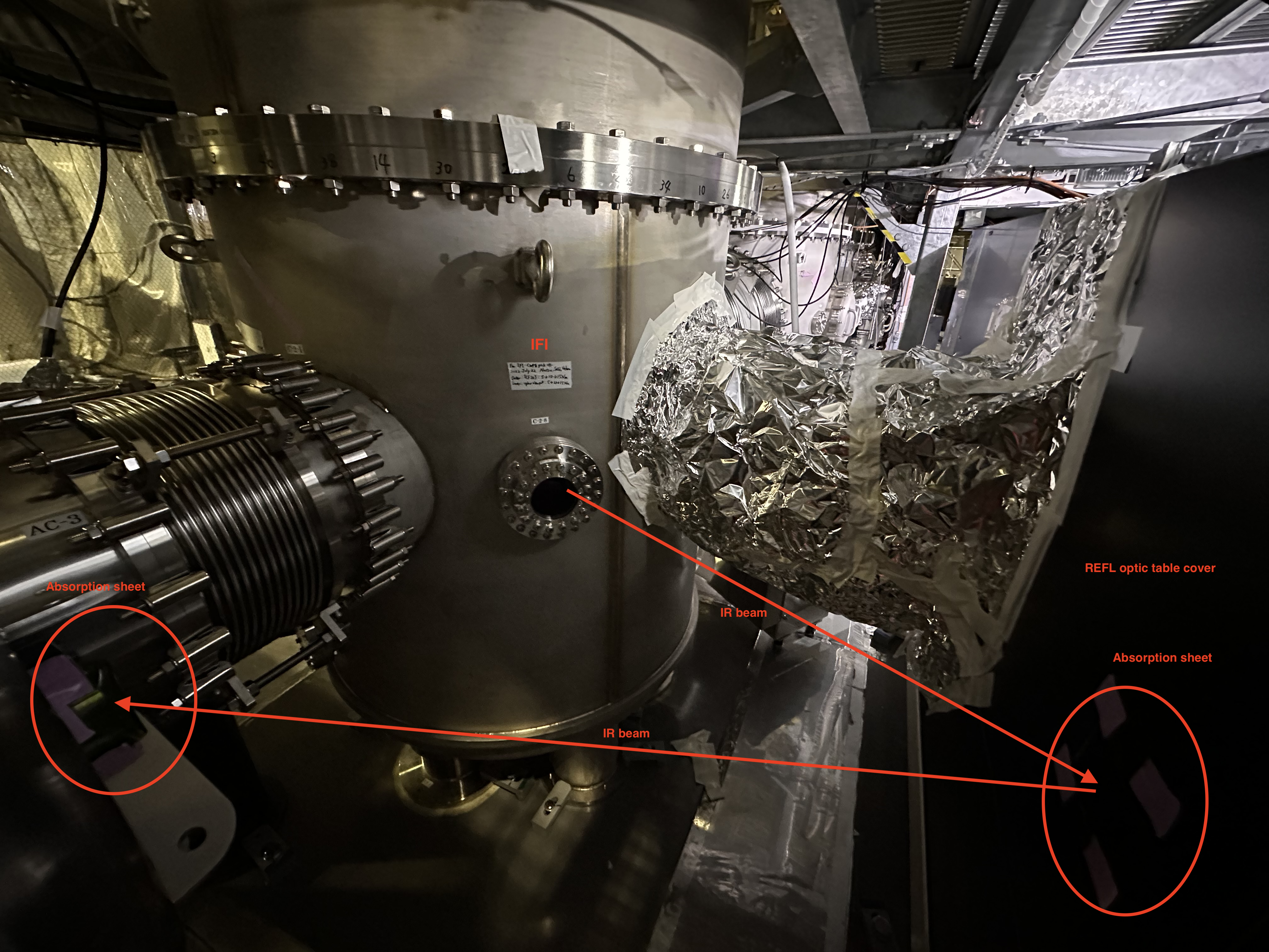
Hypothesis 3: the beam jitter would be due to scattered light at input optics such as undumped light for the IFI pick off. To test this, we need to enter the tunnel to deal with the current ad-hoc setup. To be done later.
Hypothesis 4: the beam jitter would be originally in the PSL room. To test this, we tried to see newly set-up QPD on the PSL table but the signal channels had not been DQ at the required rate. To be done later.
Discussion
Assuming the beam jitter would be real, what is the senario that the beam jitter would be converted to DARM through PRC? PRC would convert the beam jitter to amplidude modulation (or vice versa... which is larger?), but so far we could not find strong clue of such amplitude modulation in, for example, POP_FORWARD SUM (note that this PD is within PRC). Maybe this feature would be too faint. Need more careful investigation. Before entering PRC, can we have additional clue whether this would be real beam jitter? For example, ISS channels such as PSL-ISS_FIRST_SERVO_PDA_{INF,RIN}_OUT_DQ showed small coherence but not large. Anyway, for effective discussion, it would be better to take time to make noise budget first.
Anyway, as mentioned above, we already know there would be undumped beam of the IFI pick off. Also we know that stuffs on the REFL table have not been organized yet; setting proper beam dumps at proper locations to dump ghost beams, and cleaning up every unused or loosen screw or part; mechanical parasitic resonances should not be underestimated.
The situation might improve if we can improve S/N of CARM. The power on RFPD for REFL RF45 seems too small (a few x 0.1 mW?) now. Powering-up itself can be done by rotating the relevant HWP in front of this RFPD, but simultaneously we need to reduce gain of the servo. Today (On Feb 9)we tried it during PRFPMI-OMC lock but failed - gain reducing seemgly made large shock to the CARM loop. We may need to re-consider gain allocation of this servo for this purpose.