[Nakano, Enomoto]
We estimated the noise coupling from sensing noise at REFL to DARM. In particular, shot noise and PD dark noise.
1. Noise coupling from CARM to DARM:
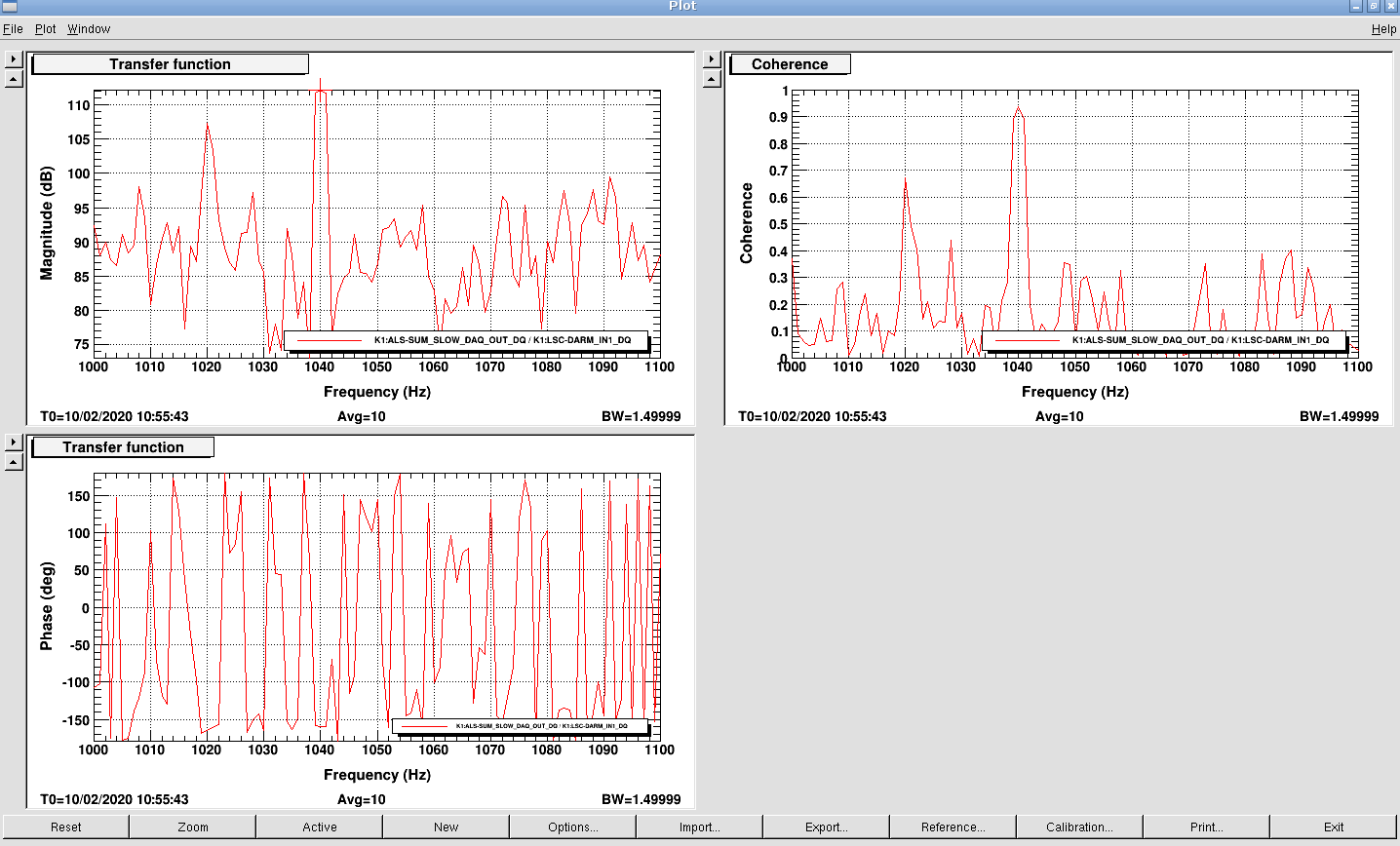
We inject sinesodial signal at 1040 Hz from CARM IN2 (via DGCARM connected to Summing node), and measured the transfer function from SUM_SLOW_OUT_DQ to DARM_IN1.
The measured coupling (DARM_IN1 / CARM_IN2) was -112 dB (First figure).
By taking various calibration factors into account, the coupling from CARM IN1 to DARM in [m] was derived as 3 x 10⁻¹⁰ [m/V]
2. Shot noise estimation:
As we know how much power is hitting on the REFL PD, it is rather easy to describe the shot noise level in [W/sqrt(Hz)].
So, we estimated the gain from RF power [W] to the demodulator output [V]; Optical power [W] --> photodiode [A] --> RFPD output [V] --> Demodulator output [V]
(i) photodiode:
We assumed the responsivity to be 0.7 A/W.
(ii) RFPD:
Combining the measurement result of transimpedance (1910675) and simulation of modified RFPD (REFL PDA1), we estimated the transimpedence to be 500 Ω.
(iii) Dual I&Q demodulator (High bandwidth):
We measured the response of an I&Q demodulator that is same type to what is installed for REFL sensing.
We put 10dBm signal to LO (45MHz), and put -10dBm (=200mVpp) signal to RF Input (45.001MHz), and then monitored the I and Q outputs of the demodulator.
The amplitude of each output was 1.16Vpp at 1kHz, meaning that the gain of the demodulator was inferred to be 5.8.
In total, with 3mW on the REFL diode, the shot noise level was calibrated to be 7.1 x 10⁻⁸ [V/sqrt(Hz)].
3. PD noise measurement:
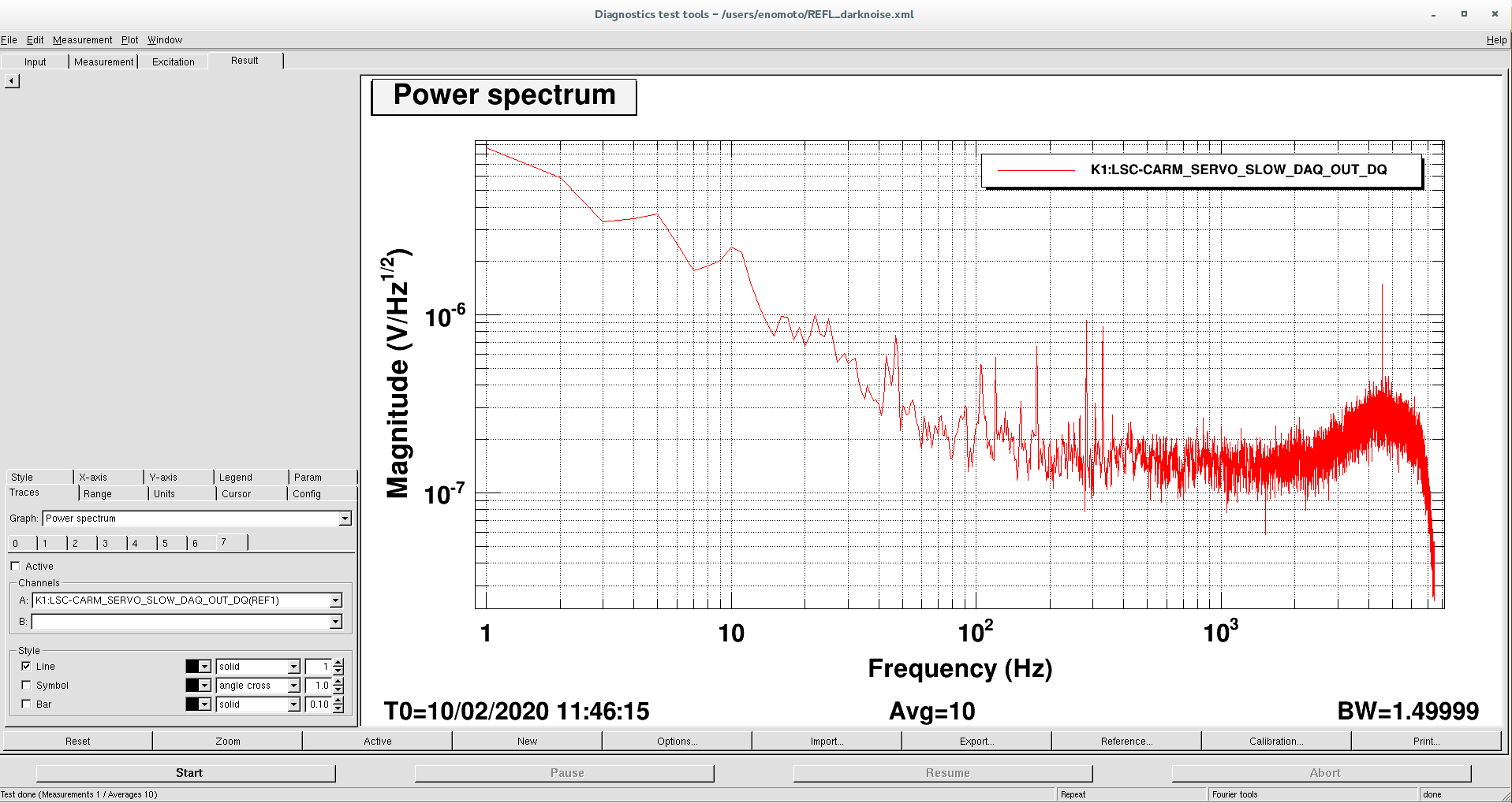
We measured the REFL PD circuit noise by using CARM board as a pre-amp.
The noise level is shown in the second figure.
4. Noise projection:
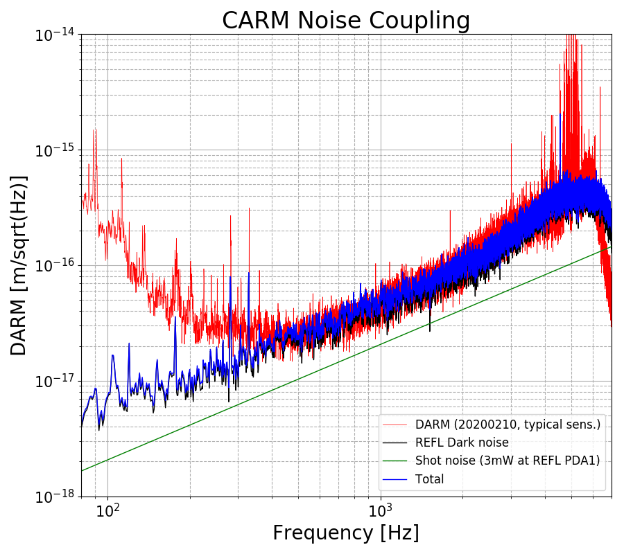
Combining the above results, we made the following projection plot, by assuming that the coupling is proportional to f
This clearly indicates that sensing noise at REFL port is limiting the sensitivity above ~400 Hz

