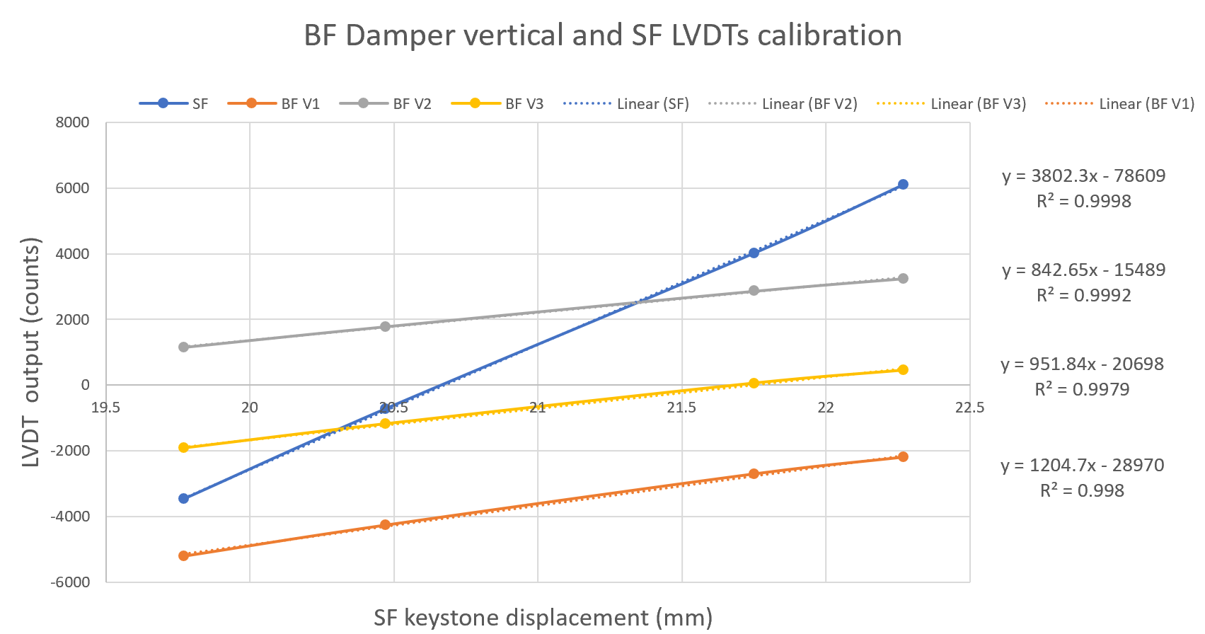
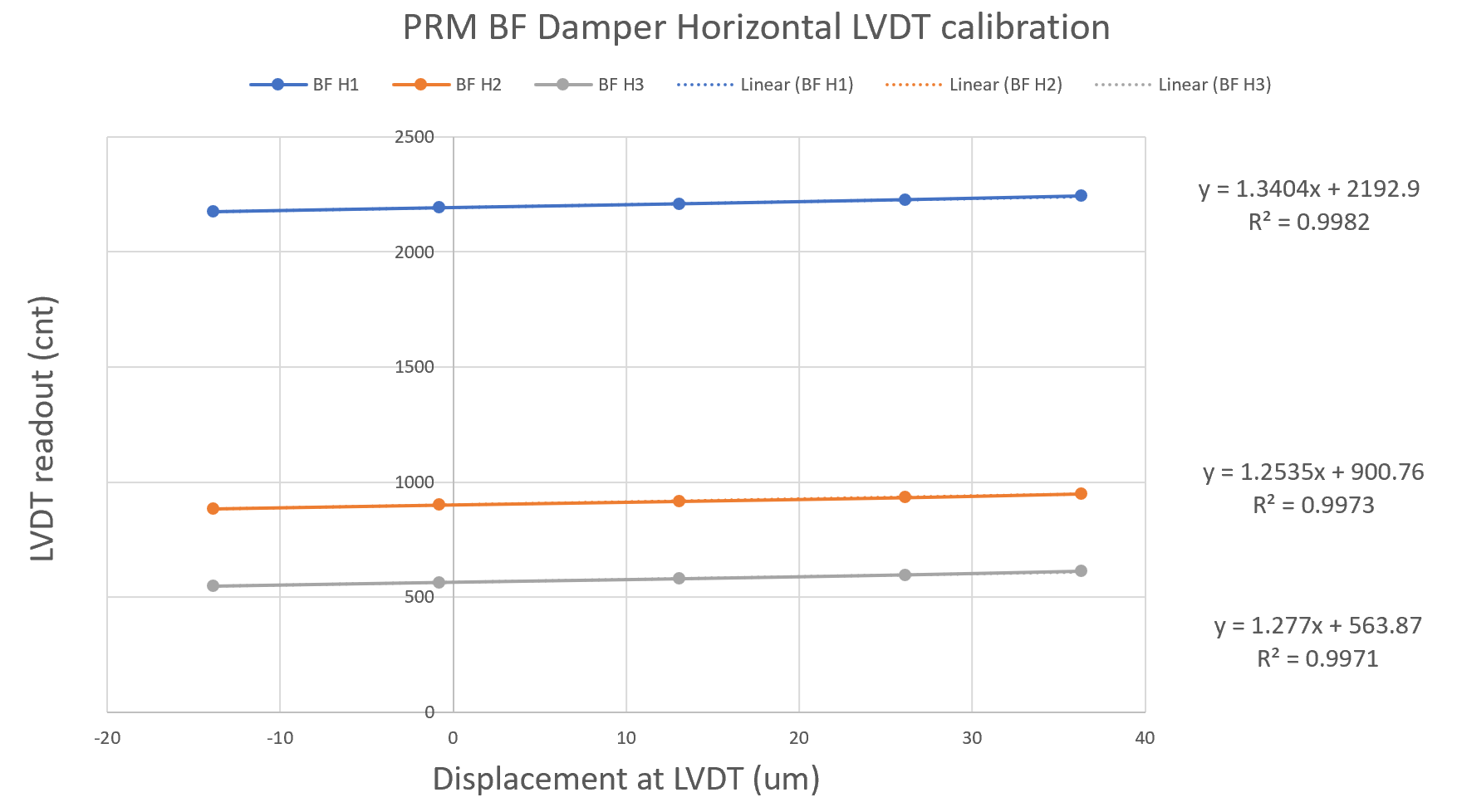
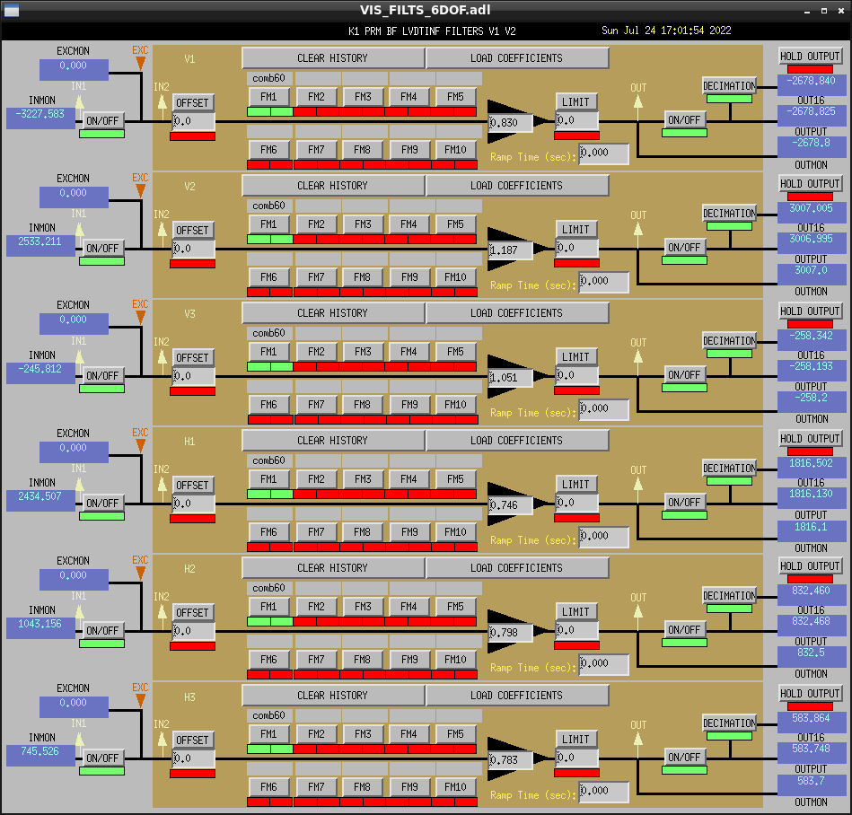
Summary: I calibrated the BF horizontal LVDTs.
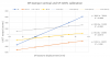
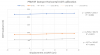
It is an approximate calibration because it relies on the oplev yaw readout, which I assume is reliable. In case we find it is not reliable, we can repeat the calibration if necessary.
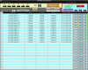
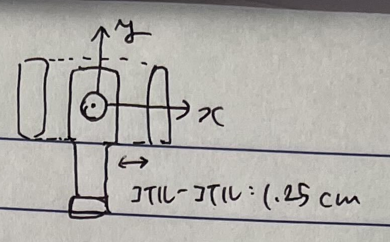
I converted the values in µrad to µm by multiplying by 408 mm / 1000, where 408 mm is the distance of the BF Damper LVDT to the centre of rotation (per JGW-D2113320-v5).
| Device | New calibration factor in Excel worksheet (cnt/um) | New calibration factor for medm screen (um/cnt) | Old calibration factor in medm screen (um/cnt) | Ratio New/Old |
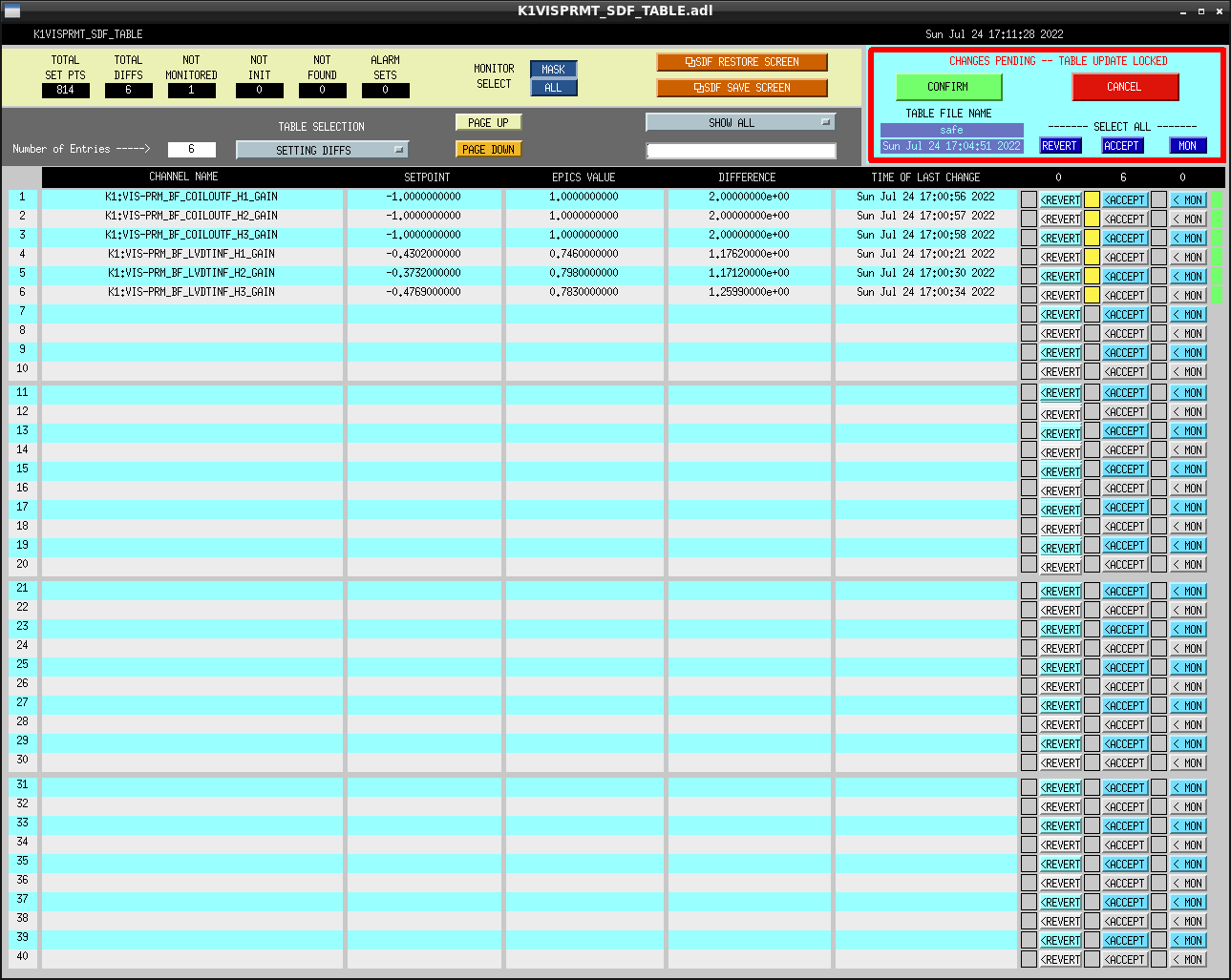
| BF H1 | 1.3404 | 0.746 | -0.430 | -1.7 |
| BF H2 | 1.2535 | 0.798 | -0.373 | -2.1 |
| BF H3 | 1.277 | 0.783 | -0.477 | -1.6 |
In average, the new calibration factors are 1.8 times larger than the old ones.
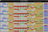
The old calibration factors have a minus sign. That is likely to make it consistent with the actuation at the BF Damper (see in the worksheet the actuation values used to move the BF Damper). However, it's not consistent with the oplev. I'll check the signs before committing the new values to the medm screens and the SDF.

