Related to 16690. R. Takahashi, Yano, K. Tanaka, Akutsu + Hirata; Hirata-san's report 16925; see also Takahahi-san's post 16922.
Abstract
To make the IMMT1 height in nominal, lowered the height of IMMT1 in 10 mm by replacing the base plate (from 25 mm thick to 15 mm) under the suspension bottom plate.
Preparation
- Detached a K400 seal flange off the IMM chamber in -Y direction for increasing accessibility to the IMMT1 suspension and the surroundings.
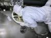
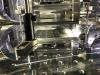
- Detached a broken beam dump (Fig. 1) that was in front of the IMMT1 suspension (see 15543) to catch a strange ghost beam (P-pol) from the IFI; for widening the work area.
- Detached all (three) black shield plates off the IMMT1 suspension structure (see here for the drawings; see 7595 and 7599 for the installation in the past) so that we could access the contained pendulum. And detached L-angle brackets as well, because we needed the M12 screw holes that were used to fix the angle brackets. The next time we attach these shields would be after any visual inspection for the suspension will be completed.
Fixing the IMMT1 mirror
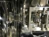
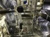
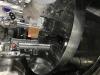
Takahashi-san fixed the IMMT1 mirror (Fig. 2). He also brough a (some?) restrait and attached it (Fig. 3) to limit the bellows vertical springs; this made the intermediate mass (IM) fixied-ish(?), according to him.
Replacing the base plate under the IMMT1 suspension structure
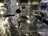
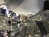
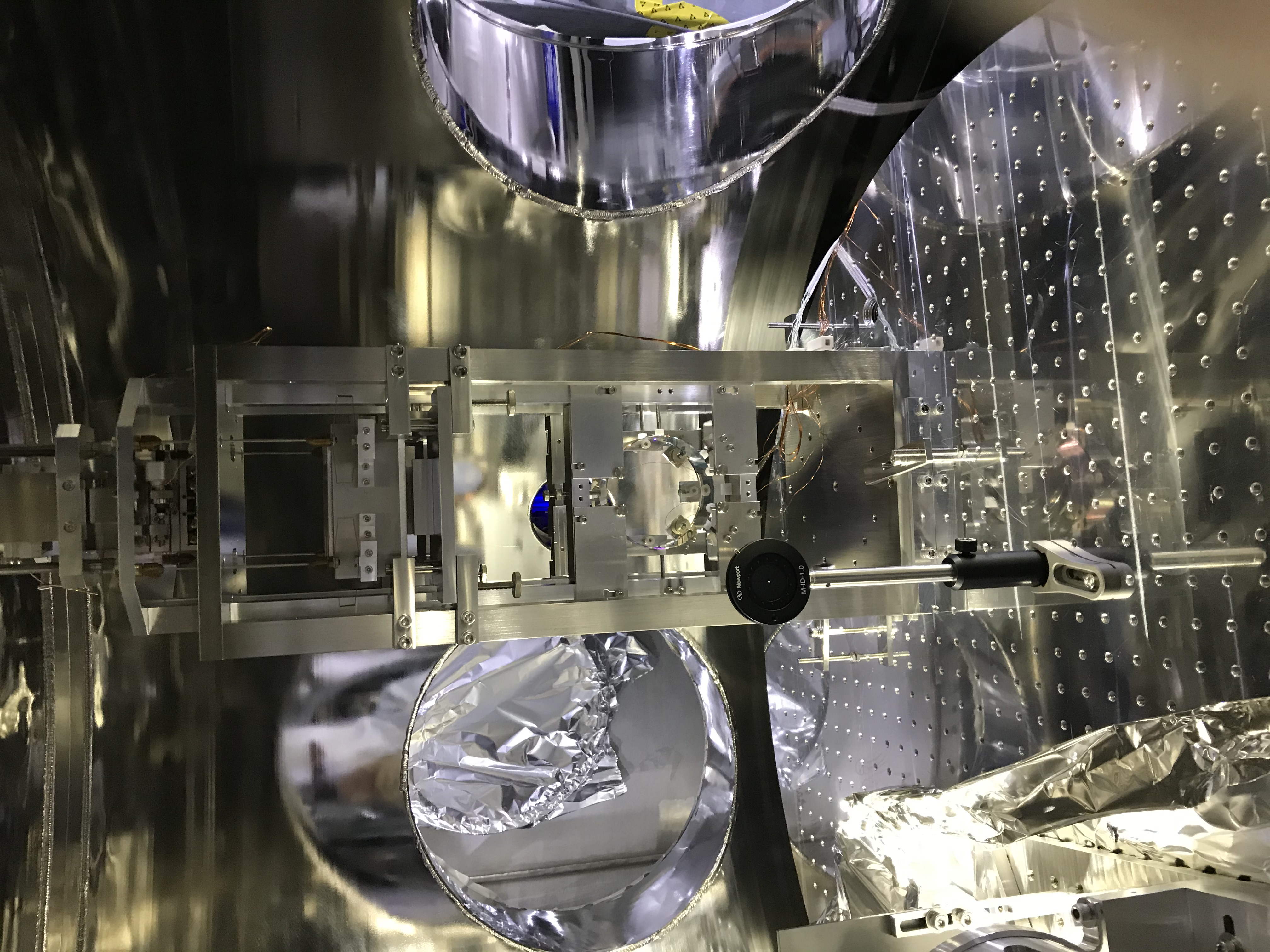
With a jack jis designed by Yano-san (Fig. 4), we lifted up the whole IMMT1 suspension structure (Figs. 5 and 6). The jig needed the M12 screw holes on the pillars of the suspension structure, that is why we detached the L-angle brackets as described above. Firstly we thought the jacking-up height would be sufficient with 0.1 times a few mm or so. But immediately we leaned that the base plate mechanically interfered against the pedestal for an iris that I put the other day, when we tried to take out the base plate from -X direction; I never wanted to move the iris, as it is a "marking stone" (oki-ishi) for the past optical axis (see 16728).
We jacked up more to somehow overcome the pedestal's the outer-most diameter, but it got stuck and I could not take it out. Finally we learned that the base plate could be taken out from the opposite side, i.e. +X side somehow!! Felt likely a chie-no-wa (a traditional 3D puzzle to disentangle entangled complicate stuffs) or jigoku-gumi (a traditional wooden architecture with which the building is hard to disassemble)
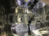
Then we inserted a new base plate (15 mm thick; the drawing to be uploaded...) under the bottom of the IMMT1 suspension structure (Fig. 7). Again with the jack jig, we lowered the suspension structure on the new base plate. Using three dog clamps the suspension structure was fixed tightly to the top surface of the optical bench together with the base plate (Fig. 8). By the way, note that the suspension will be rotated in yaw soon for proper initial alignment of the IR beam into the main interferometer.
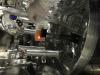
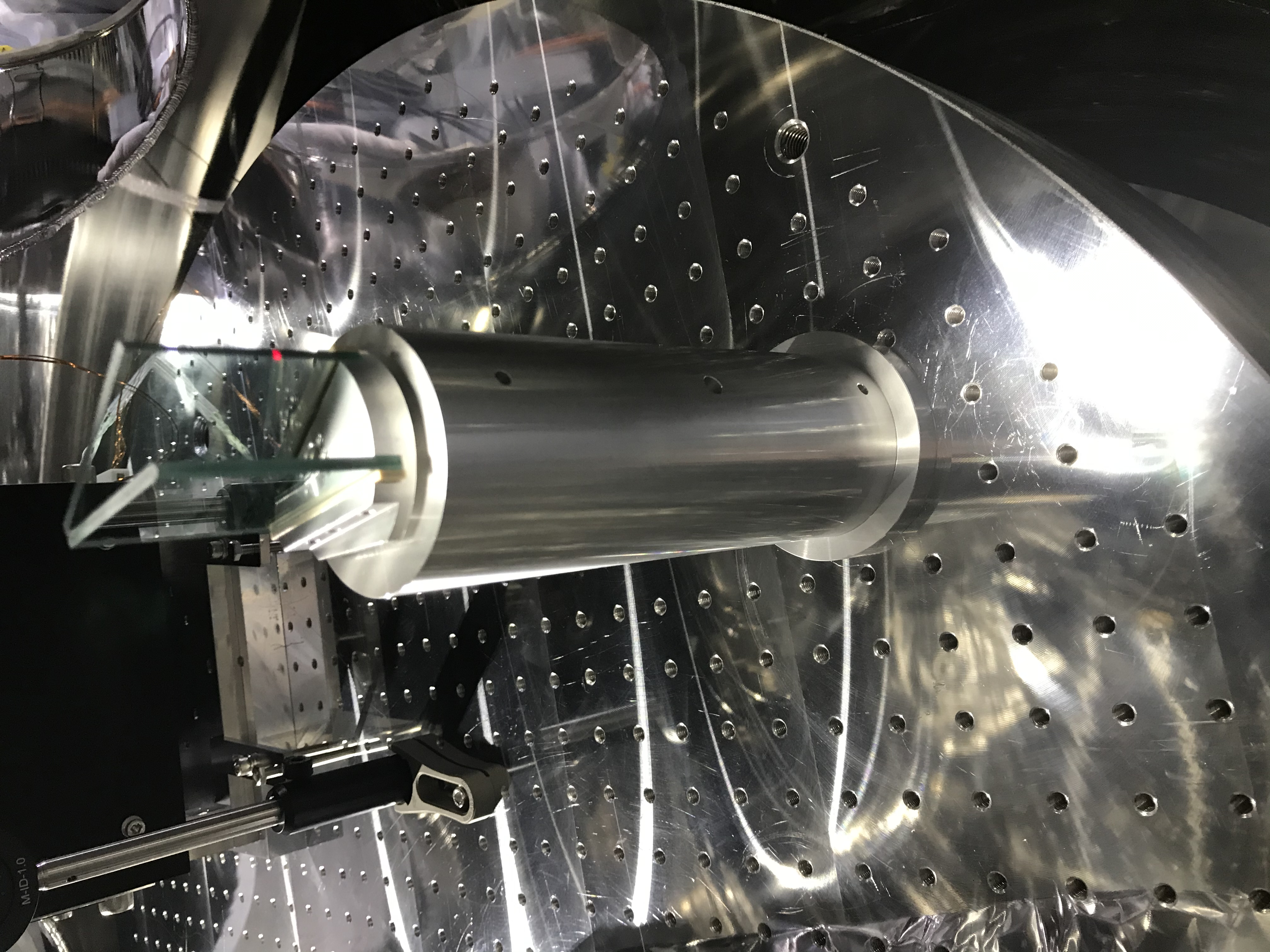
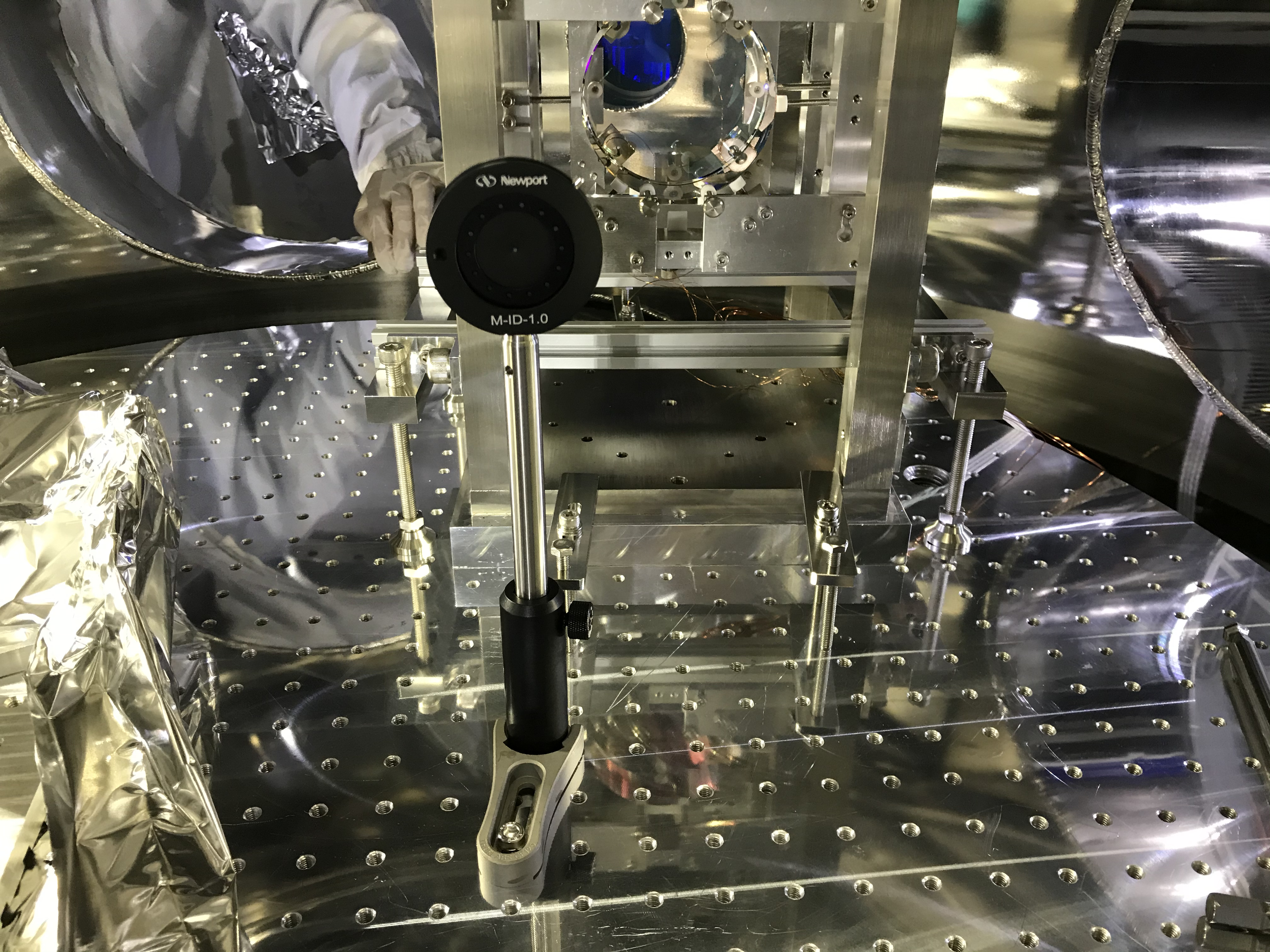
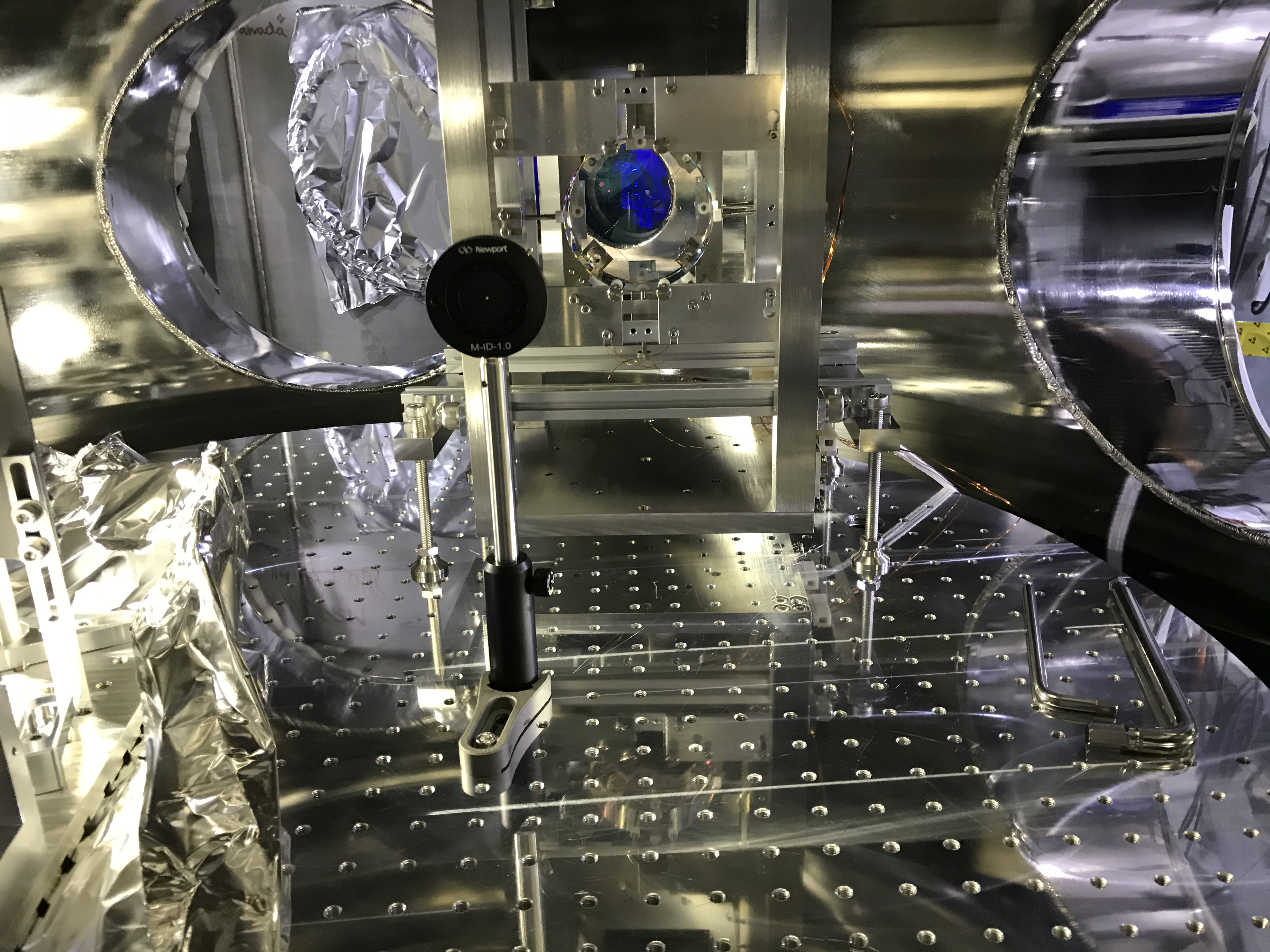
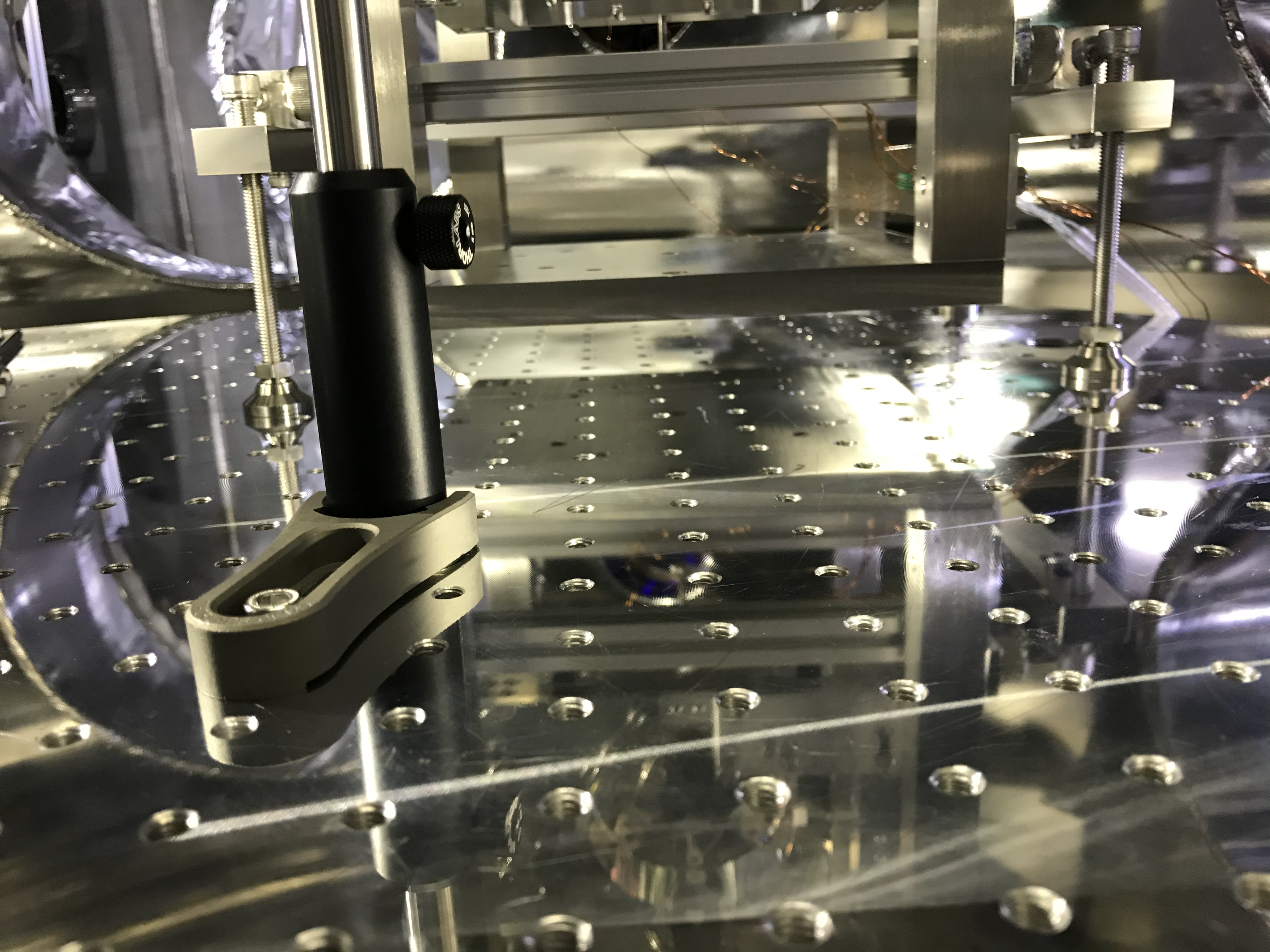
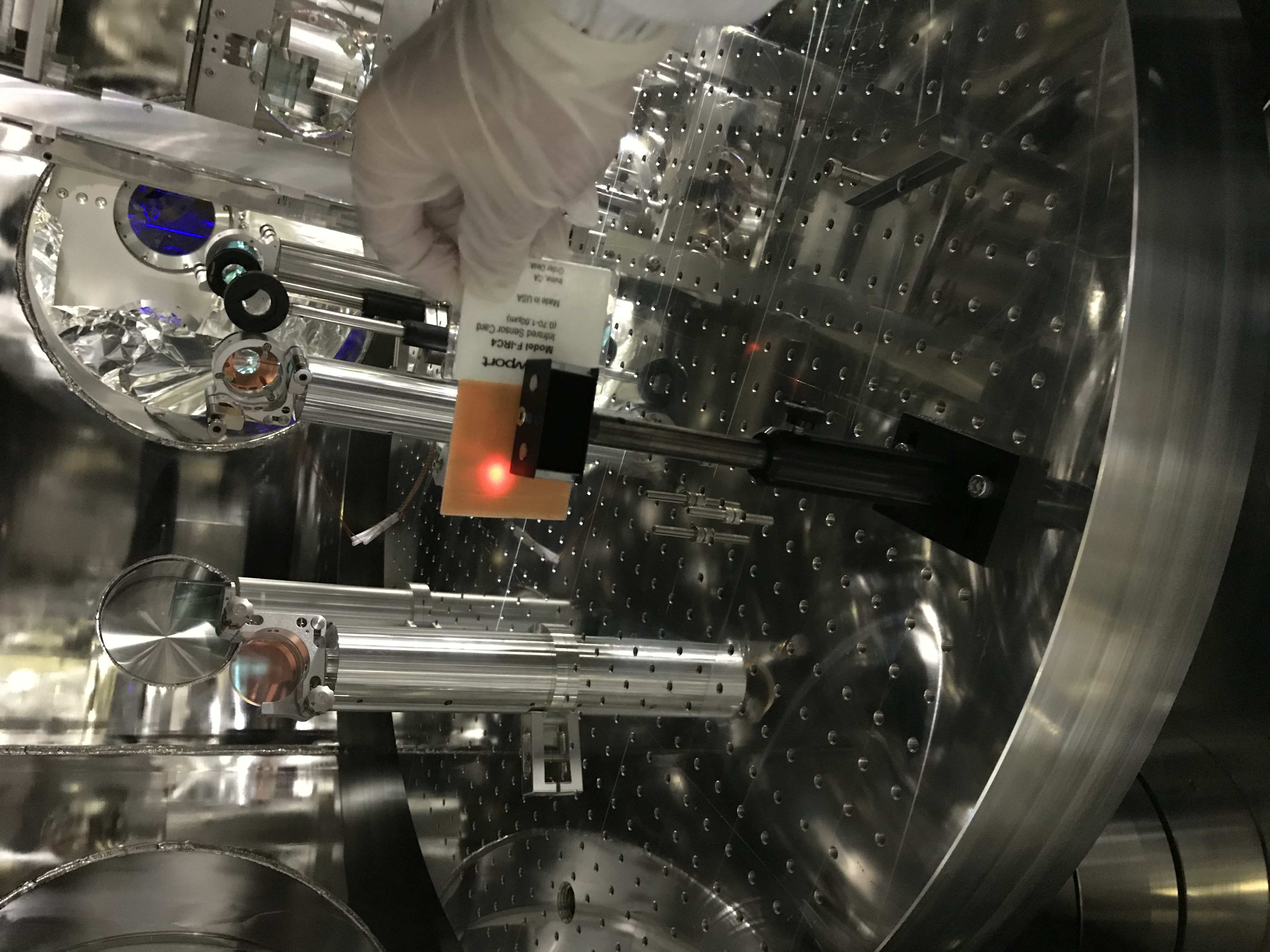
To check the unwanted rotation of the structure, we input the IR laser beam. The reflected beam from IMMT1 was slightly rotated, but the amount was small (Fig. 9). We relocated the beam dump to catch this beam as of today (Fig. 10).
Setting positioners around the IMMT2 suspension
For the next work, in the IFI chamber, we set positioners around the IMMT2 suspension. Also attached some metal stuffs for limiting the move direction of the suspension; actually these metal stuffs are just dog clamps found there. Hopeing these stuffs can limit the IMMT2 suspension so that it can move only in -Y-ish direction (firstly we like to achieve a parallel move along the side surfaces of the base plate under the suspension.)
