K. Tanaka, Akutsu
Abstract
Tweaked STM2 to reflect the IR light beam to IMMT1, and re-arrange the optics on the IMMT1_TRANS optical bench and the QPD.
Details
We carefuly looked around the things on the IMMT1T bench as of today. Thanks to Miyakawa-san, a heavy structure has been already removed (see 16616). We ad-hoc-ly considered a tentative (but forevere???) setup on this optics bench. There are:
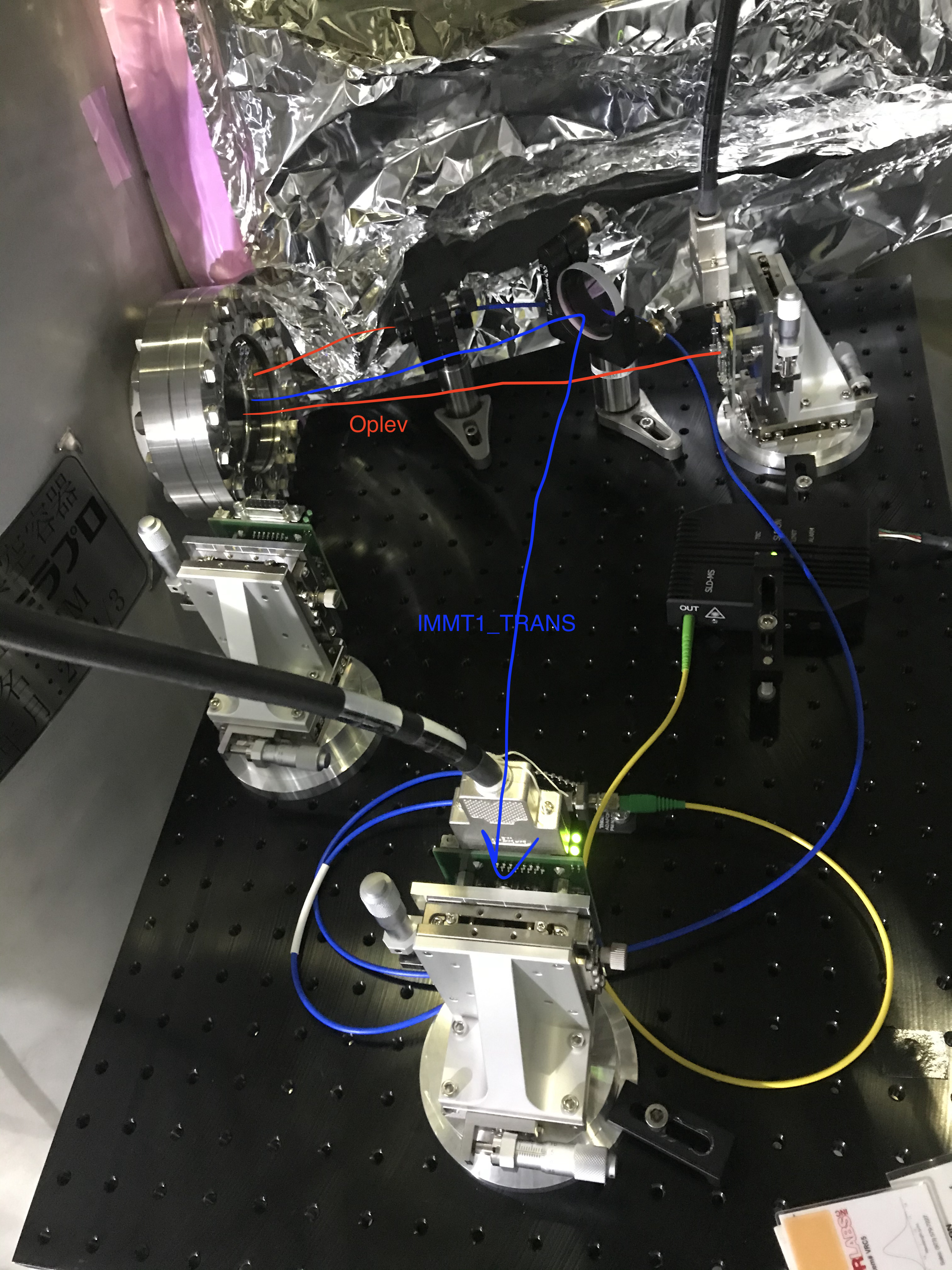
- IMMT1 oplev (tilt)
- IMMT1_TRANS (forward) QPD for input beam poiting.
By the way, as the IFI has been already detached, the beam reflected at STM2 was just hitting the IMMT1 suspension structure (see 16690). So we tweaked the STM2 to have the reflected beam wentto the (roughly) center of IMMT1. I was worried that the reflected beam from STM2 might be clipped with one of the iris diaphrams put for preserving the optical axis (see 16690), but luckly that did not happen. But we removed an SiC aperture from the IFI chamber, and stoked in the shelf close to the MCF chamber, as the SiC aperture was in the way of our alignment work.
Using the transmitting beam from the AR of IMMT1, we were able to complete the tentative optics setup on the IMMT1_TRANS bench. The result is shown in the attached figure. Because the separation between the oplev reflected beam and the IMMT1_TRANS foward beam, we put an ad-hoc steering mirror (of 2inch) in the optical path of the IMMT1_TRANS. The holder may have to be replaced with a more stable one.
We measured beam powers (with a Thorlabs' PD-type power meter, the same one introduced here) at some points:
- In-between STM2 and IMMT1 HR: 0.348-0.345 W
- After the IMMT1 chamber viewport: 0.778 mW
- After the steering mirror in front of the QPD for monitoring the IMMT1_TRANS beam: 0.764 mW
So, IMMT1 transmission seems ~0.22%, while 0.3% is a nominal designed value with the nominal aangle of incident according to this wiki. Note that, in the near future, most of the power will be picked off to the ISS beam path. Because the incident angle of the main IR beam to IMMT1 would not be nominal today, the transmissivity might not be consisten with each other. Let's see.
Notes
- The beam size on the IMMT1_TRANS QPD seemed large. According to here, the theoretical value is 2.5413mm radius. The measurement will be done later.
- As Miyakawa-san reported in 16616, the pylon for the IMMT1T (and IMMT1 oplev) is a bit shaky. Revisit this later.
- Some optical parts were removed from the IMMT1T bench, and as of today they were brought around the table near MCF. I do not know tomorrow.
- The reflection from the IMMT1 hits one of the pillars of the IMMT2 suspension cage, and makes scattered light now; to be dumped. I waas worried if some iris diaphrams that I put might clip the beams but that does not happen. Lucky.