Yano, Akutsu After detaching the K400 flange from the IFI chamber (see here).
Abstract
Took out the IFI and its base plate from the vaccum chamber. Later, we will lower its total height 9.9 mm (0.39 inch) by machining the base plate. Note that the one that had been assembled in a wrong height was IFI as noted in JGW-D1503538-v5, but in reality, rather, we will modify the base plate for easiness. (it is not still easy, though.)
Preserving the optical path 1
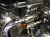
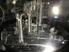
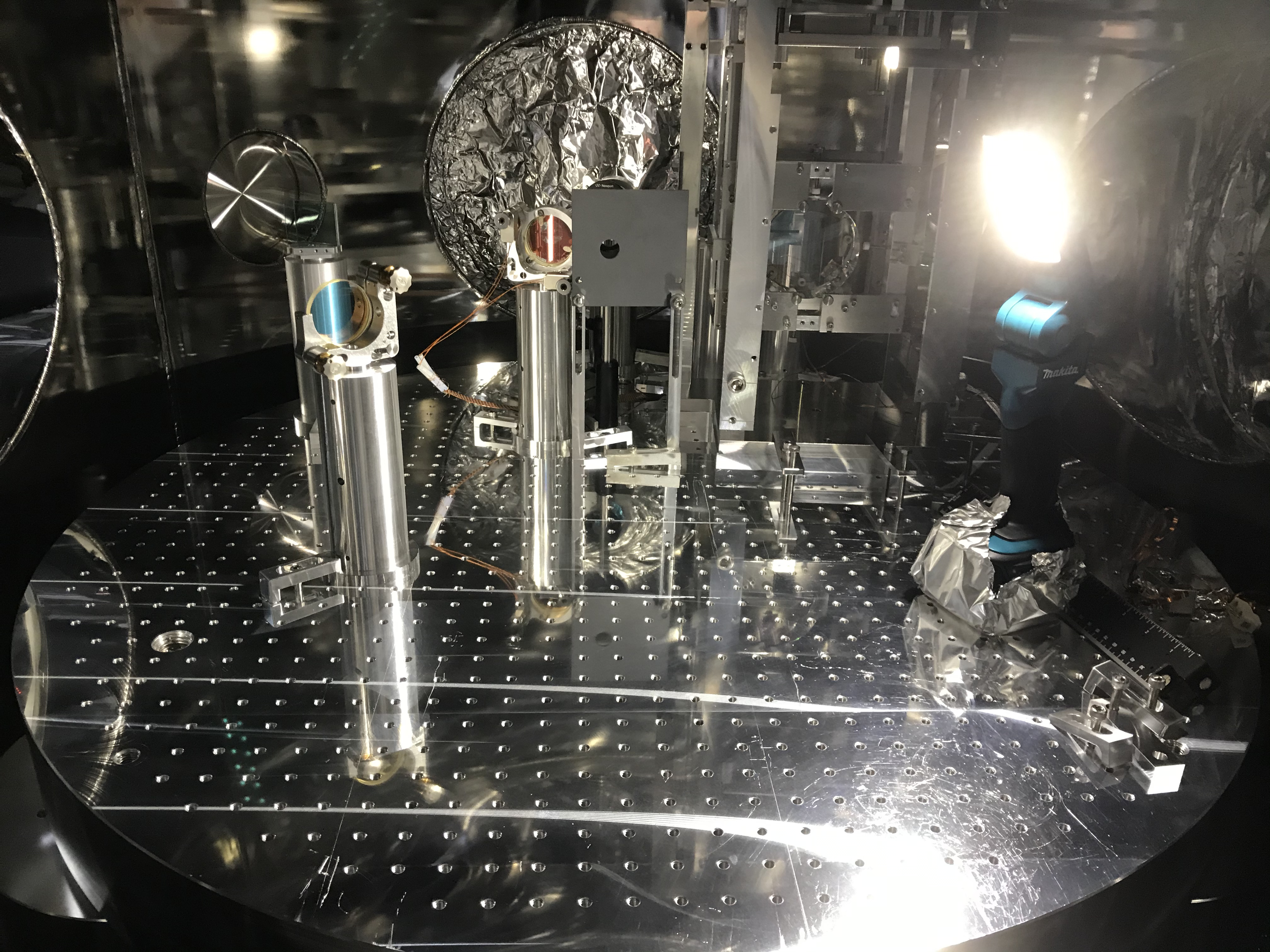
Continued from 16626, we put three iris diaphragms each in front of STM1, STM2, and the first aperture made of SiC by referring the transmitting beam from IMC; the lock was so stable to do these works! (Fig. 1). Actually, to tweak the iris at STM2, we needed to remove the K400 flange (see here).
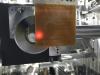
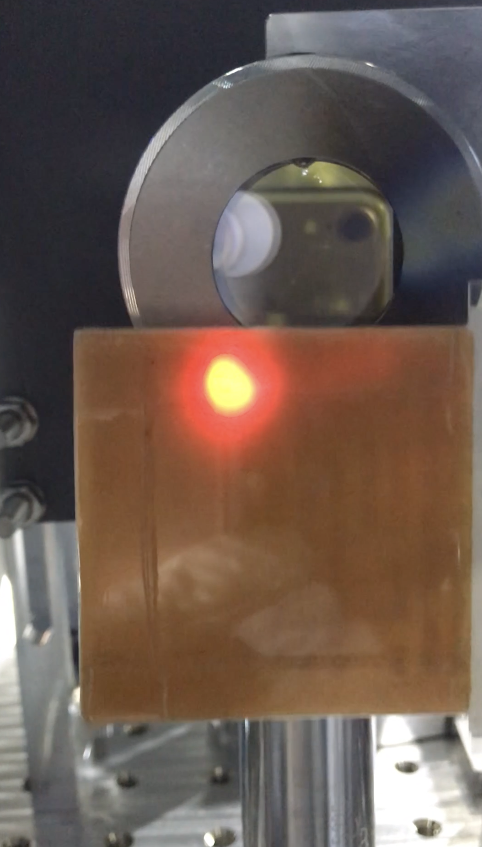
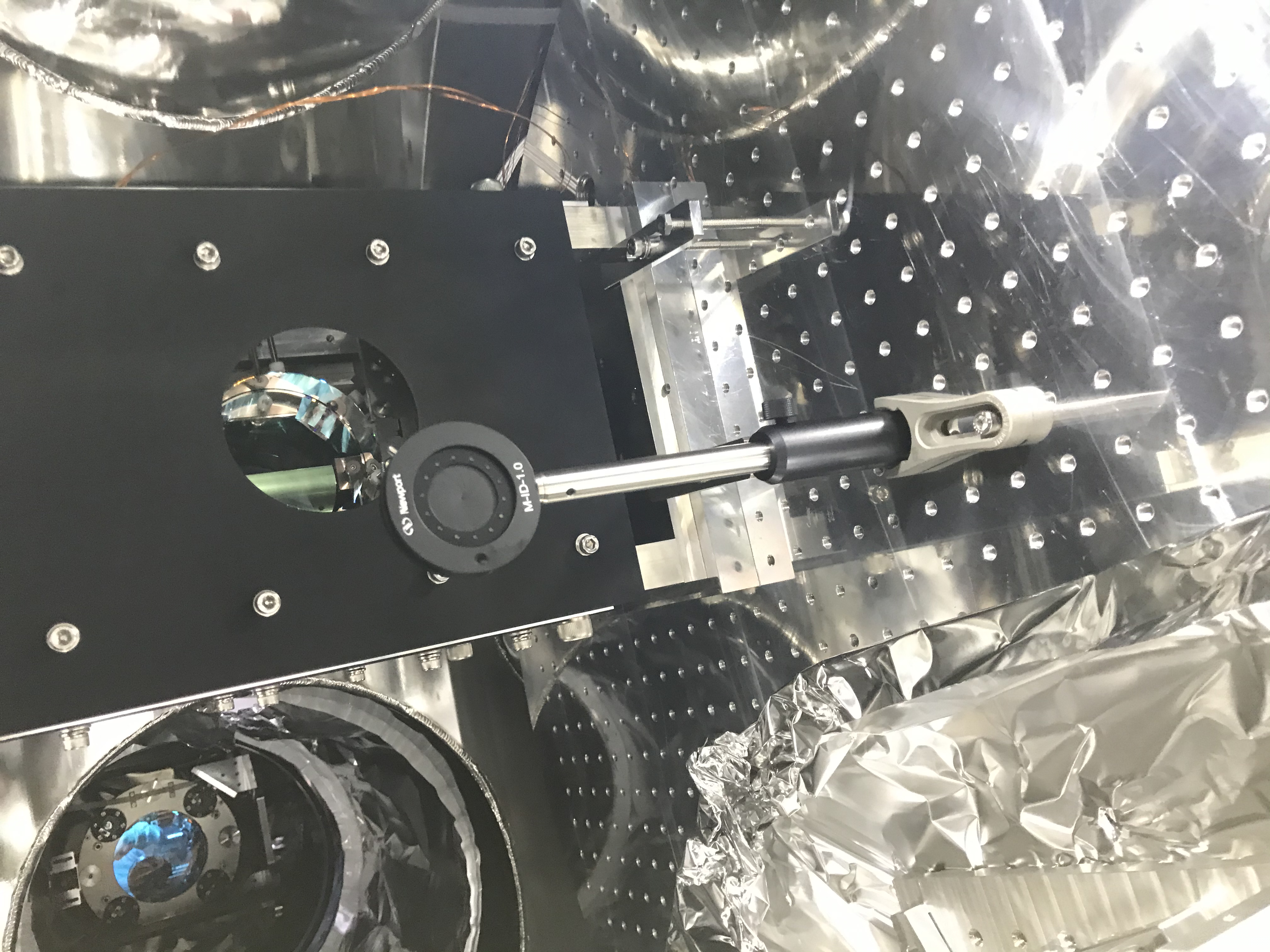
By the way, when opening all these iris, the beam transmitted the IFI (slightly lower than the center, Fig. 2), and reached IMMT1, then IMMT2, then PRM, and finally come back to the IFI and illuminated the CWP2 holder (Fig. 3).
Scribbling the base plate
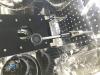
Then, with a scribble needle, we copied the outer shape of the IFI assy to the top surface of the base plate somehow. Dut to that the bottom of the IFI assy has some grooves periodically, the scribbled lines were also jumpy. We also measured some relative position and alignment so on. We also made scribble lines of the outer shape of the base plate to the top surface of the optical table in the IFI (may be this was not need, though I loved being more information).
Detaching the IFI and the base plate
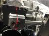
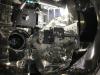
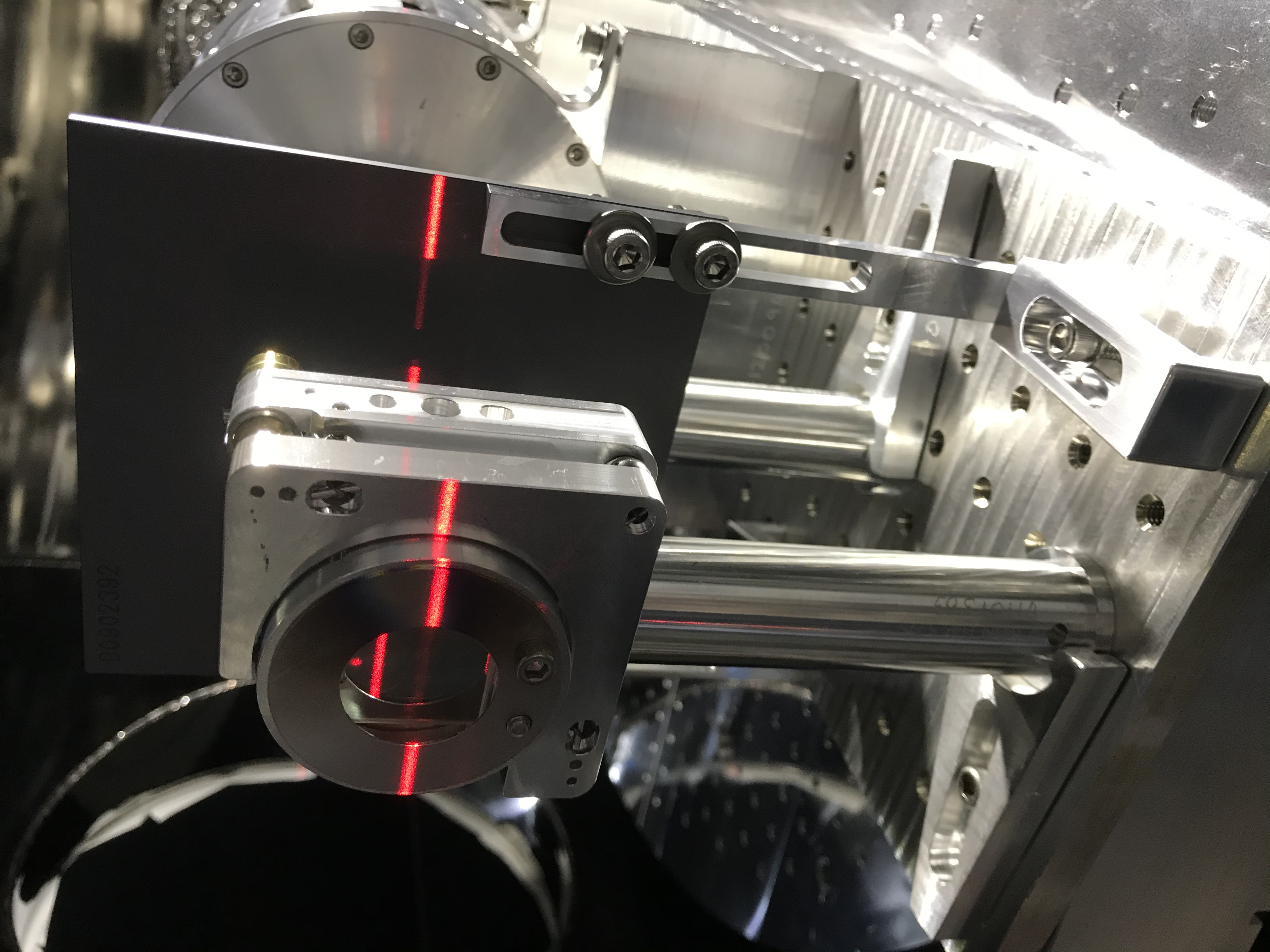
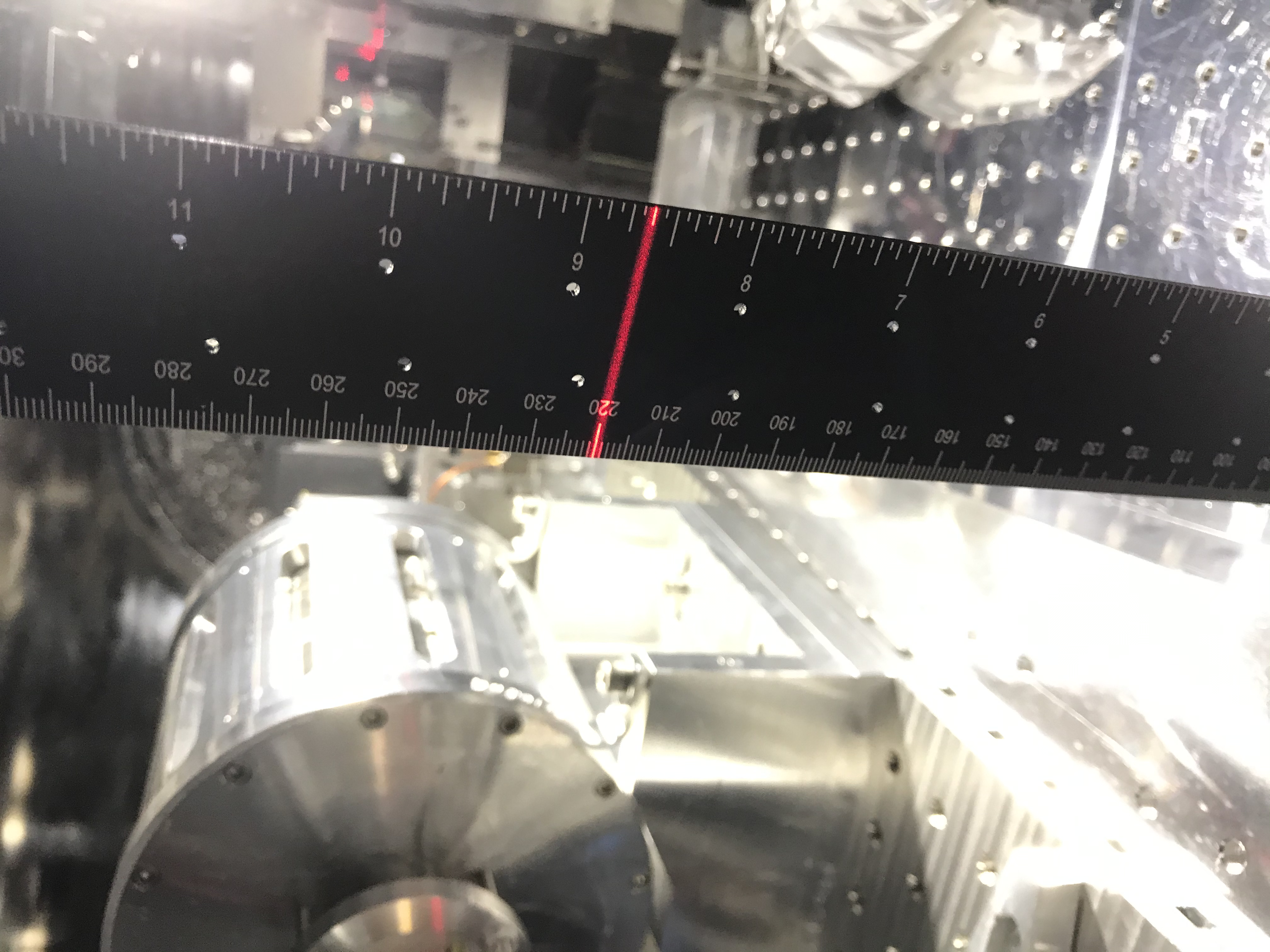
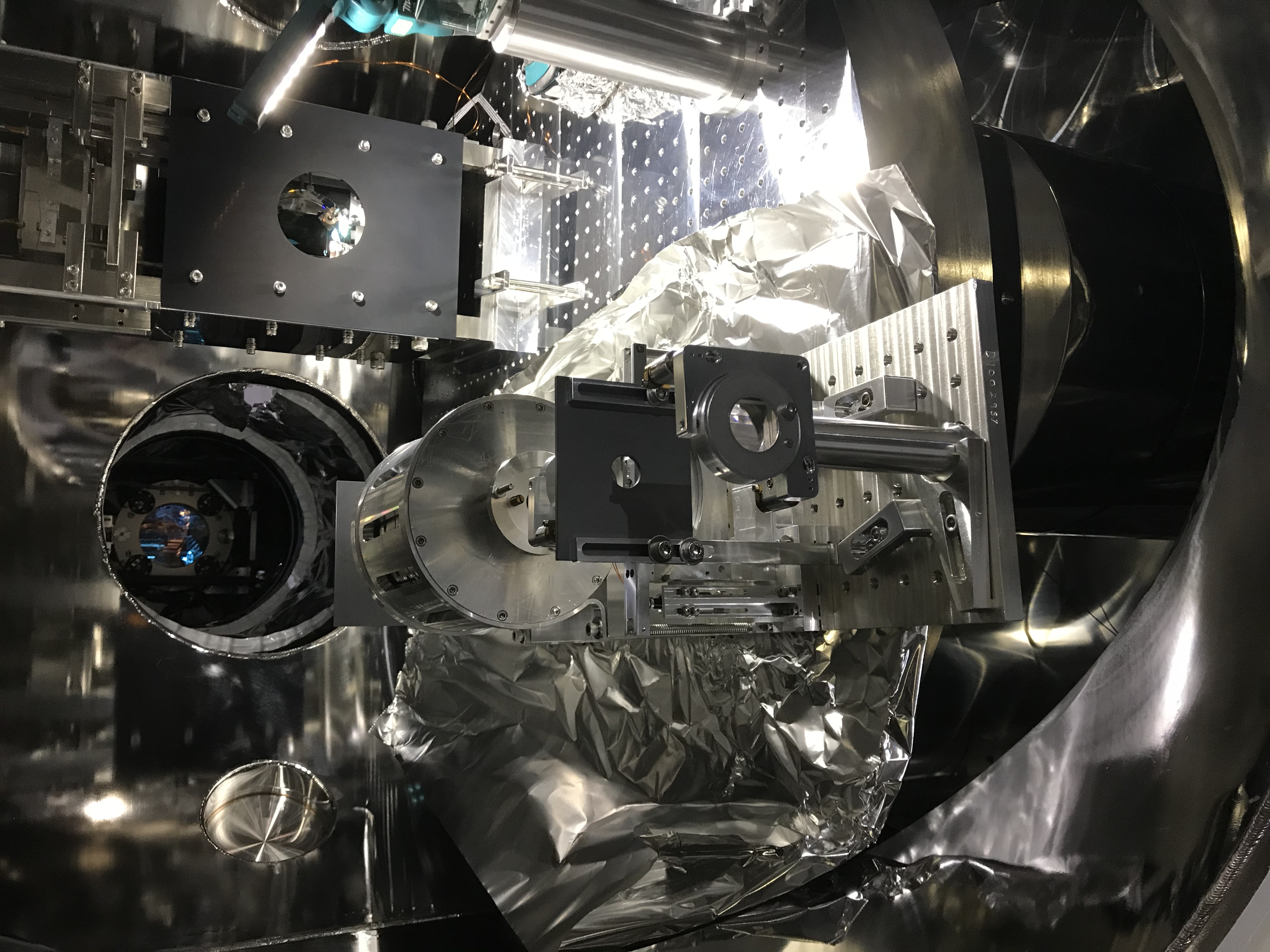
With our human arms, we lifted up the IFI assy and moved it into the IMM chamber; an aluminum sheet was underneath the IFI assy. It was heavy... By the way, before moving the IFI, we did the final check of the height mismatch of the IFI, and seems around 1 cm (Figs. 4 and 5), which is consistent with our thought. Now it is in the IMM chamber (Fig. 6)
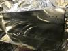
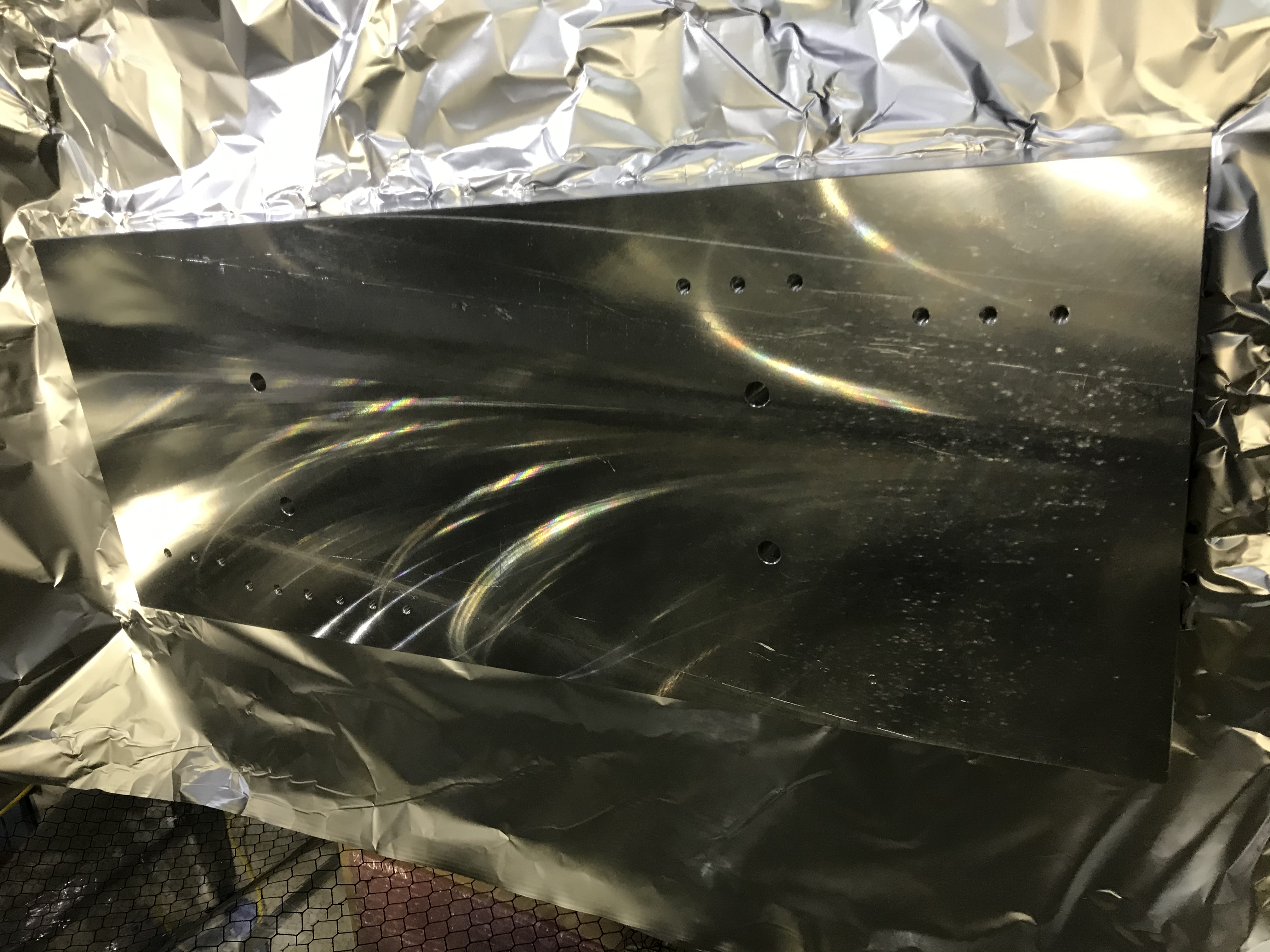
The outlooking of the base plate was haevy, but it was light than our imagine. So we detached (Fig. 7) and packed it; will be sent to Mitaka for machining. Now the IFI chamber becomes cleaner (Fig. 8).
Preserving the optical path 2
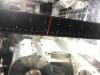
After detaching the IFI at all, we put an iris to make a reference for the beam without IFI. This iris will be an important reference when we will get back the IFI soon (Fig. 9).
Notes
- We need to move the IMMT2 suspension anyway (see 15799). For this work, the IFI may have been an obstacle, so detaching the IFI would help the workability.
- The IFI was fixed with four dog clamps, which should be re-designed when we will get back the IFI assy, because they may not be usable. The new dog clamps should be adjustable in the height.
- The IFI base plate was fixed with four screws directly to the optical table. Seems the oversize of the hole was not large, so it would be ok for the preciseness, but maybe too severe for the actual installation. It is a little bit hard to adjust the base plate on the optical table to the level of the required preciseness. Maybe using positioners might be helpful.
- To continue the IMC-ASC experiment, the reflected beam from STM2 should be tweaked so that it hits the center of IMMT1. Later on. Soon.
