[M. Honjo, Michimura]
We have reduced the PD gains for TMSX and TMSY polarization monitor PDs to avoid saturation in 10 W PRFPMI operation.
Power at TMS PDs seems to have half the power than estimation for some reason (as was the case in 2018 and 2022).
Summary of PD whitening situations:
X_IR_PDA1: 0 dB, no whitening gain, no whitening filters
X_IRSPOL_PDA1: 0 dB (was 10 dB), no whitening gain, 2-stage whitening filter
X_IRPPOL_PDA1: 10 dB (was 30 dB), no whitening gain, 2-stage whitening filter
HWP angle: 20 deg
Y_IR_PDA1: 0 dB, no whitening gain, no whitening filters
Y_IRSPOL_PDA1: 0 dB (was 10 dB), no whitening gain, 2-stage whitening filter
Y_IRPPOL_PDA1: 20 dB (was 30 dB), no whitening gain, 2-stage whitening filter
HWP angle: 80 deg
See klog #30902 for previous settings. Note that X and Y have different settings now.
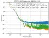
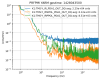
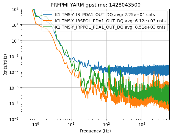
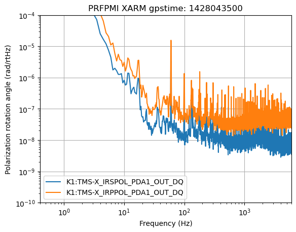
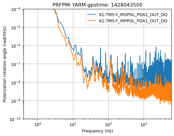
Calibrated polarization spectra:
- We calibrated measured spectra into polarization rotation angle using the factor described in klog #30885. But with following changes
if ARM=='X':
PDp2Rad=1/(4*(300.7-16.3)*np.sin(4*np.deg2rad(20-10.1)))*10**(20./10) # Calibration from klog #30113, but calibration was done in 30 dB, but now in 10 dB
PDs2Rad=1/(4*(297.0-19.7)*np.sin(4*np.deg2rad(20-54.7)))*10**(30./20) # Calibration from klog #30113, but calibration was done in 30 dB, but now in 0 dB
PDp2Rad/=130*10.8/1.1/2 # 130 for PRFPMI instead of single arm, 10.8/1.1 for input power difference, 2 for installation of additional BS in TMS (klog #32183)
PDs2Rad/=130*10.8/1.1/2
elif ARM=='Y':
PDp2Rad=1/(4*(358.0-24.1)*np.sin(4*np.deg2rad(80-72.5)))*10**(10./20) # Calibration from klog #30827, but calibration was done in 30 dB, but now in 20 dB
PDs2Rad=1/(4*(352.0-24.2)*np.sin(4*np.deg2rad(80-117.4)))*10**(30./20) # Calibration from klog #30827, but calibration was done in 30 dB, but now in 0 dB
PDp2Rad/=130*10.8/1.1/2 # Same with X (klog #32181)
PDs2Rad/=130*10.8/1.1/2
See attached for the original data in counts and the calibrated data for X and Y.
TMS power budget:
- Using the following, power transmitted from ETMX and ETMY would be 420 mW and 395 mW, respectively. Since we have 4 BSs to IR_PDA1 now (JGW-T1808962), power at IR_PDA1 would be 26.2 mW and 24.7 mW, respectively.
PIMC=10.8
PRG=13.0
BS=0.5
T_ITMX=0.444/100 # PhysRevApplied.14.014021
T_ETMX=6.8e-6 # PhysRevApplied.14.014021
T_ITMY=0.479/100 # PhysRevApplied.14.014021
T_ETMY=6.92e-6 # PhysRevApplied.14.014021
RTLX=50e-6 # Round-trip loss klog #30823
RTLY=60e-6
def cavitypowertransmission(T1,T2,L):
L=L-T2 # Remove ETM transmission from round-trip loss
t1=sqrt(T1)
t2=sqrt(T2)
r1=sqrt(1-T1)
r2=sqrt(1-T2)
rloss=sqrt(1-L)
return (t1*t2)**2/(1-r1*r2*rloss)**2
T_XARM=cavitypowertransmission(T_ITMX,T_ETMX,RTLX)
T_YARM=cavitypowertransmission(T_ITMY,T_ETMY,RTLY)
P_TMSX=PIMC*PRG*BS*T_XARM
P_TMSY=PIMC*PRG*BS*T_YARM
- During 10.8 W PRFPMI lock
K1:TMS-X_IR_PDA1_INMON = 10200 cnts
K1:TMS-Y_IR_PDA1_INMON = 9530 cnts
These corresponds to 10.6 mW for X and 9.83 mW for Y, using 40/2**16 V/cnts, 1.5e3 Ohm transimpedance gain, and 0.39 A/W for PDA100A2. These are roughly a factor of 2.5 smaler than the estimated power above.
Past TMS power measurements and discussions:
- According to measurements in October 2022 (klog #22456, klog #22339), power around RLNS2 was 529 uW for X and 480 for Y with 2.9 W input, single arm. For 2.9 W single arm, using T_PRM=0.135 (JGW-L1605744), they should be 1170 uW for X and 1100 uW for Y. Here, measured values are a factor of 2.2 smaller. Note that these measurements were done with a power meter. So, the discrepancy is consistent between power measurement methods.
- This was also the case in December 2018 (klog #7415, klog #7419).
- Note that all the calculations above assume 100% modematching of IMC transmission to the main IFO. This should be a good approximation due to DARM shot noise estimates and past modematching measurements.
- We are consistently loosing half the power since 2018. Something inside BRT???
Next:
- Redo polarization calibration under 10 W PRFPMI configuration
- Set HWP angle to reasonable values and make PD gains same for X and Y

