[Yuta Michimura, Haoyu Wang]
Following the work at TMSX klog #30113, we did similar work for TMSY yesterday.
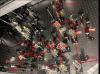
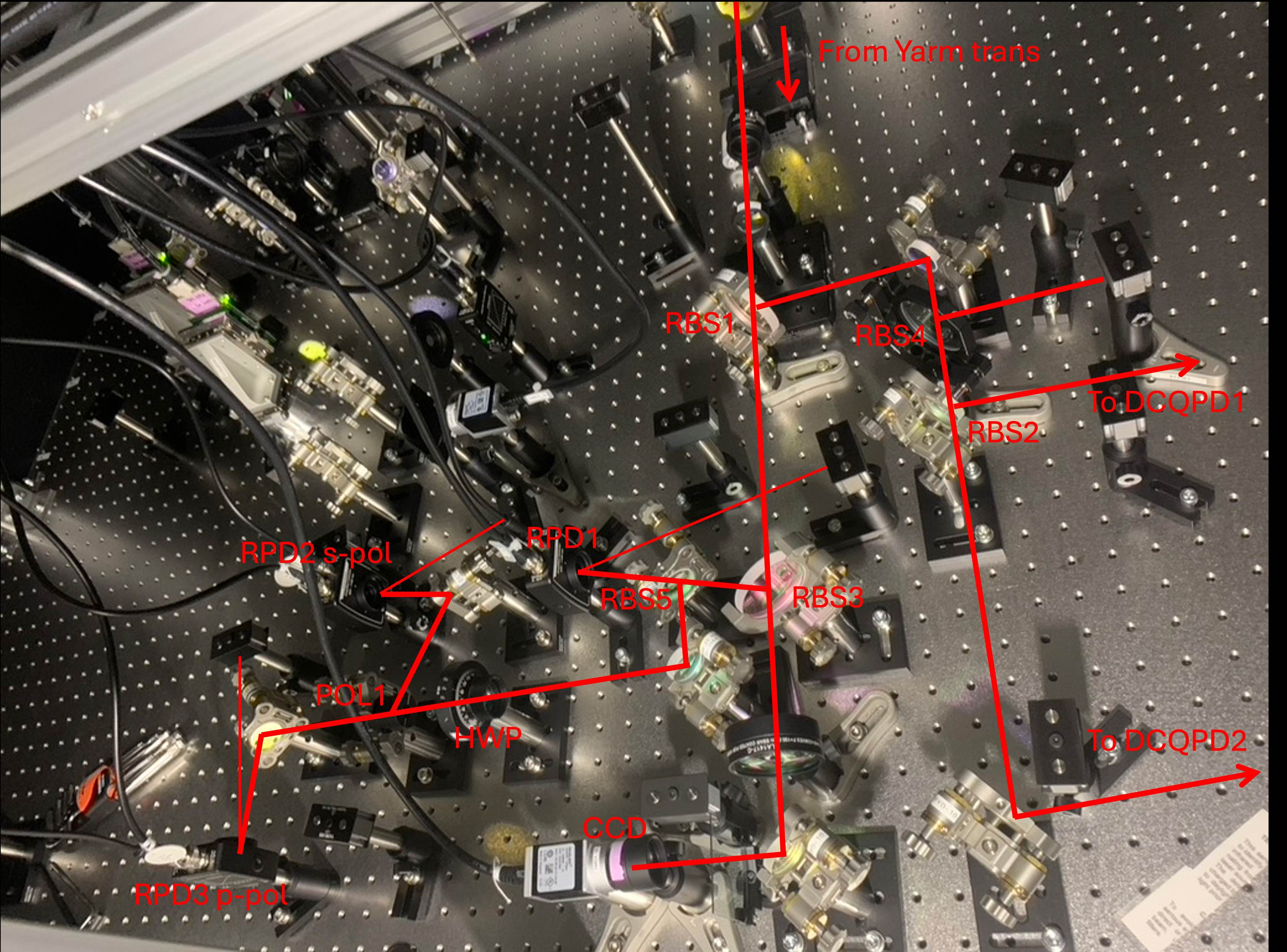
The latest configuration can be found in JGW-T1808962-v20. We replaced RBS1, RBS3 and RBS5 on the IR main beam with non-polariazing beam splitters from sigma-kk. RBS1 and RBS3 are 2-inch. RBS5 is 1-inch.
Since we replaced RBS1, we realigned the beam going to the two DCQPDs. The alignment process is done without the attenuator RBS4. After the alignment, we put the attenuator back. There may be slight offsets in the yaw signals of DCQPDs due to the transmission of the BS, but should be very small.
We aligned the IR PD (RPD1), s-pol PD (RPD2), p-pol PD (RPD3) and the CCD. Reflected beams from these sensors are properly dumped. The gains of the 3 PDs are kept the same (0 dB for IR PD, 30 dB for s/p-pol PDs).
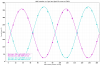
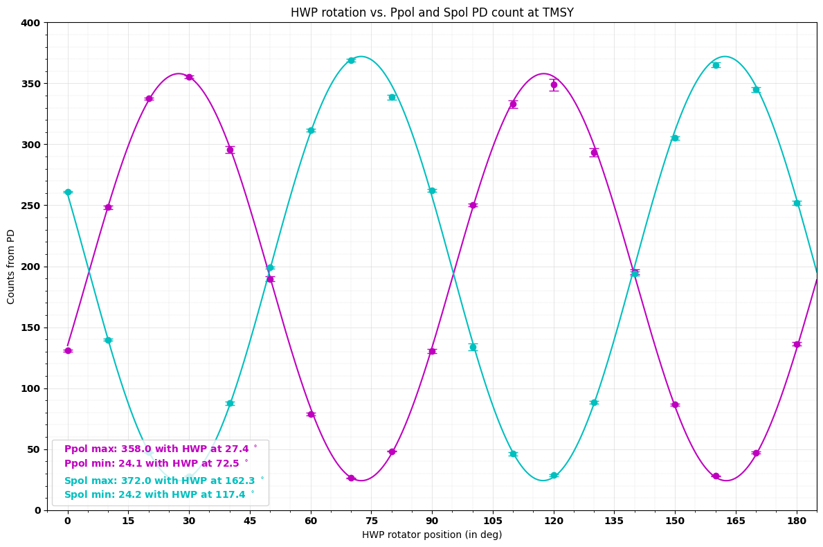
Fig 2 shows the fitting of the power change of s/p-pol PDs when rotating the HWP for TMSY. The HWP rotation for min Ppol is 72.5 deg. We set the rotation of HWP at 80 deg so that there is a small potion of light at p-pol PD.
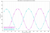
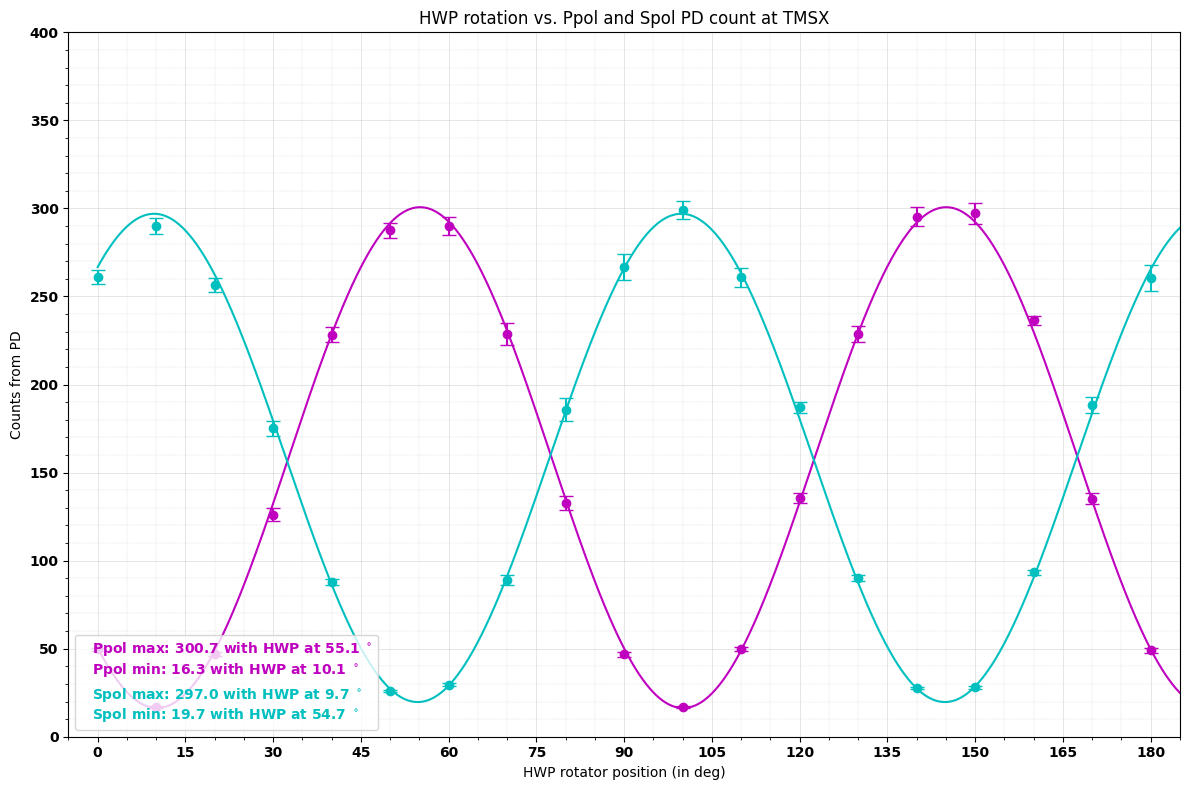
For comparison, the fitting for TMSX is shown in Fig 3.
Somehow, the max p-pol power is smaller than max s-pol power at TMSY. But at TMSX, the max p-pol power is slightly larger than max s-pol power. We suspect this is because the incident angles on PDs are different, since we found PD reading will change slightly when the incident angle is slightly changed from normal incidence.