Reports 1-1 of 1 Clear search Modify search
MIF (General)
Haoyu Wang - 22:49 Tuesday 25 June 2024 (30113) Print this report
Replacement of optics at TMSX

[Yuta, Shalika, Kenzaburo, Haoyu]

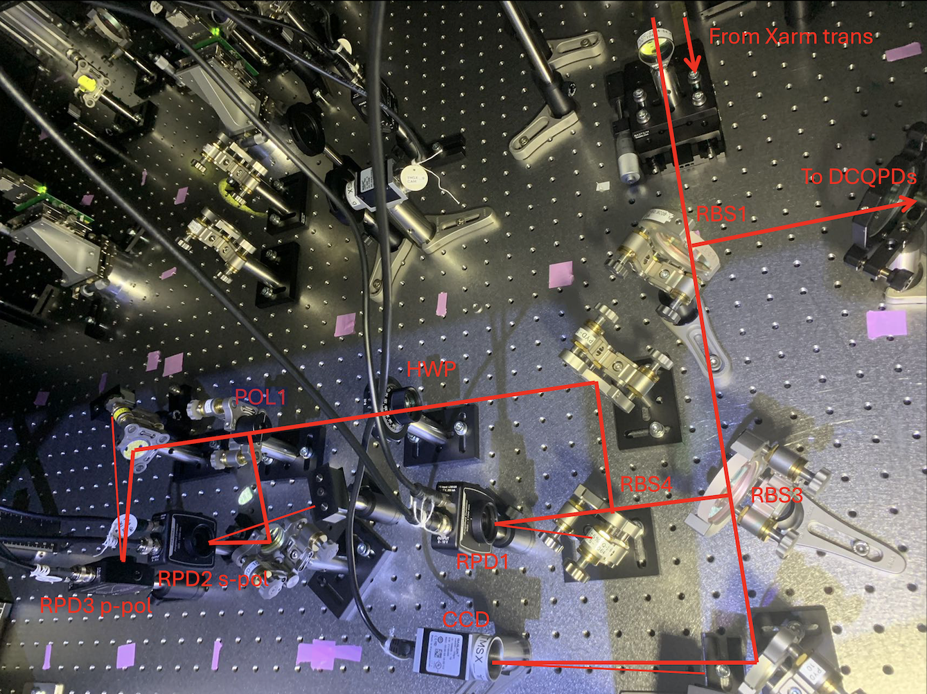
(The new layout at TMSX can be found in JGW-T1808962-v18, also shown in Fig 1.)

We replaced all BS (RBS1, RBS3 and RBS4) on the IR main beam with non-polariazing beam splitters from sigma-kk. RBS1 and RBS3 are 2-inch. RBS4 is 1-inch.

Since we replaced RBS1, we realigned the beam going to the two DCQPDs. The alignment process is done without the attenuator (the BS between RBS1 and RBS2). After the alignment, we put the attenuator back. There may be slight offsets in the yaw signals of DCQPDs due to the transmission of the BS, but should be very small.

We aligned the IR PD (RPD1), s-pol PD (RPD2), p-pol PD (RPD3) and the CCD. Reflected beams from these sensors are properly dumped.

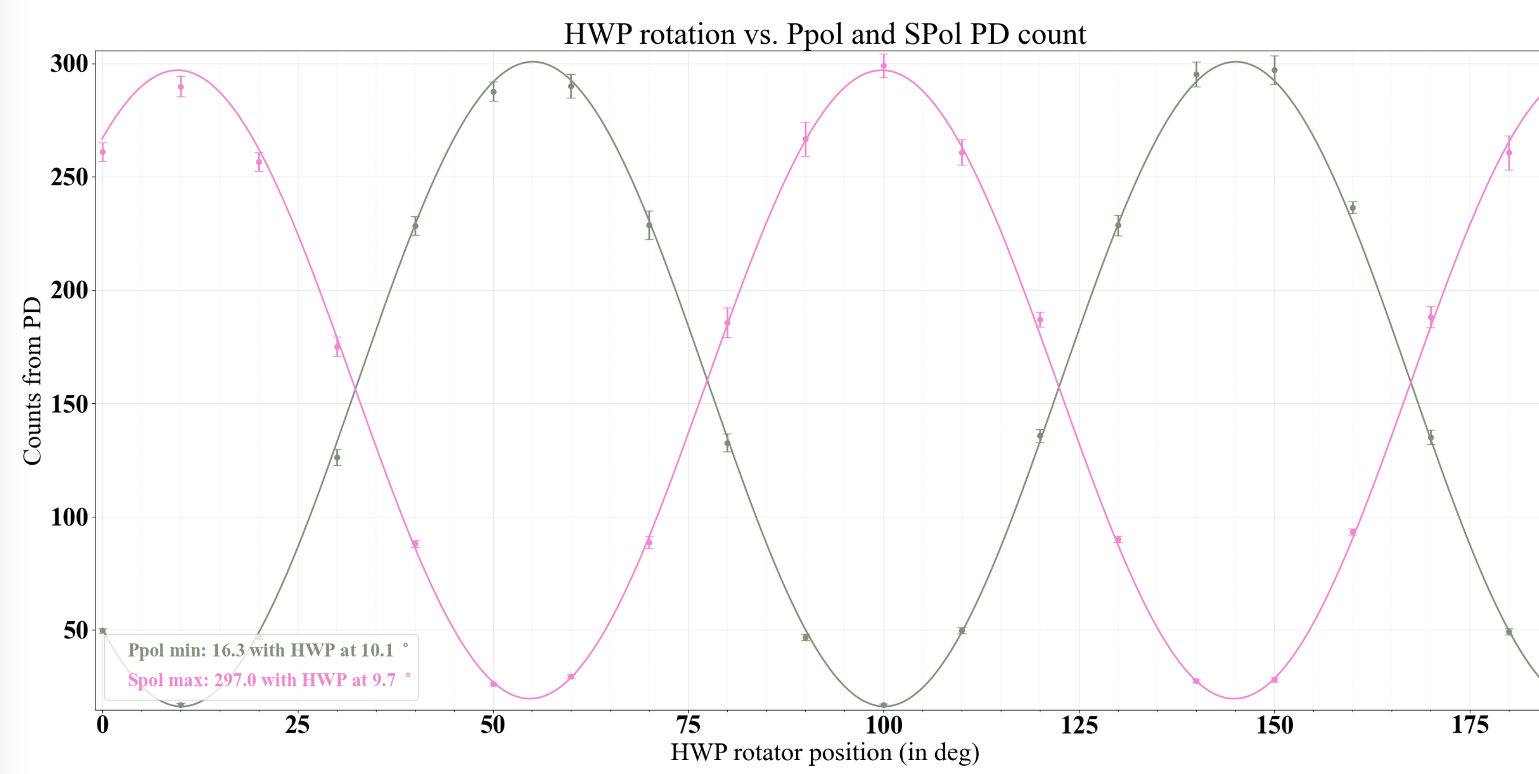
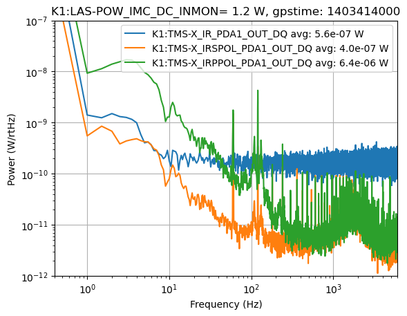
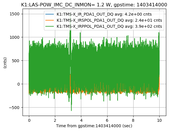
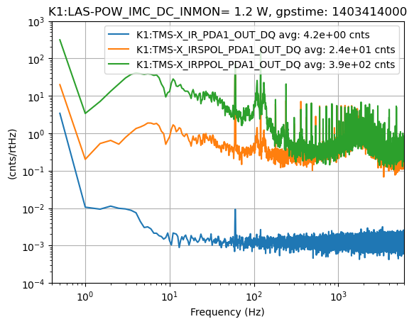
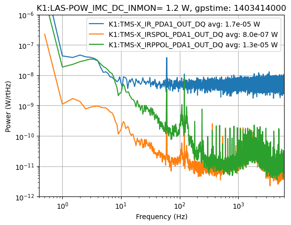
Cannels of s-pol/p-pol PDs are added on the MEDM screen. We changed the HWP readings and checked the power changes of the two PDs. The gain of the two PDs are set as 30dB. Fig 2 shows the fitting of the power change. The HWP rotation for min Ppol(16.3) is 10.1 deg and max Spol(297) is 9.7deg. We set the rotation of HWP at 20 deg so that there is a small potion of light at p-pol PD and we are going to measure their noise performance tonorrow.

By the way, we found the IR beam height  from the periscope to RBS3 is around 2mm higher than 4inch. As the mounts for the lenses RLNS1 and RLNS2 are 4-inch height, the beam is not centered for the lenses. We didn't change this.

Images attached to this report
Comments to this report:
Haoyu Wang - 0:25 Thursday 27 June 2024 (30135) Print this report

We measured the power at each port with the power meter for IR beam with the IMC trans power of 1.2W. The configuration can be found in JGW-T1808962-v19. The power is almost consistent with the measurement before with 3W IMC trans power. After we replace the BS with non-polarizing BS from sigma-kk, the reflection is always smaller than transmission. The reflection is around (45±2)%.

Haoyu Wang - 0:11 Friday 28 June 2024 (30148) Print this report

[Yuta, Shalika, Kenzaburo, Haoyu]

We measured the noise spectrum of three IR PDs at TMSX.

Gain settings used in the measurement are:

IR PD gain 0 dB, no gain and no filter in the whitening filter.

IR S-pol and P-pol PDs gain: 30 dB, 0 gain in the whitening filter but 3 filter stages are applied.

The current HWP rotation allows most power goes to p-pol.

Fig 1 - Fig 4 show the measurements.

Fig 1: time series data of 3 PDs. Some signal is oscillating in s-pol and p-pol PDs. We think this is caused by the large whitening filter gains.

Fig 2: row spectrum in counts. There are peaks around 60Hz and 120Hz. We think this causes the oscillation.

Fig 3: calibrated spectrum in Volts. The IR PD's spectrum is flat (around 1e-6 V/sqrtHz) above 10Hz, which seems to be the ADC noise.

Fig 4: calibrated spectrum in watts. There is a factor of 2 problem. The real power is roughly 2 times of the value in the plot.

We think 3 filter stages in the whitening filter for s-pol and p-pol PDs are too much. Maybe 1 stage is good.

After this measurement, we turn off all the whitening filters. We need to check this spectrum again in the PRFPMI configuration.

Images attached to this comment
Haoyu Wang - 23:26 Friday 28 June 2024 (30170) Print this report

The voltage and power calibrations in Fig 3 and Fig 4 in the last comment were incorrect. The following figures show the correct calibration.

* Fig 1: time series data of 3 PDs showing the DC output. (No change)

* Fig 2: row spectrum in counts. (No change)

* Fig 3: Updated calibration of PDs in voltage.

- Assumption for calibration: the PD output range is ±20V and the ADC is 2^16 bit.

- IR PD setting: no PD gain, no whitening filter gain, 0 filter stage, 0.255 filter bank gain.

- IR S-pol setting: 30 dB PD gain, no whitening filter gain, 3 filter stages, no filter bank gain.

- IR P-pol setting: same as s-pol PD.

(1) IR PD DC output: 4.2 counts / (2^16 counts) * 40 V / 0.255 = 1.0e-2 V

(2) IR S-pol PD DC output: 24 counts / (2^16 counts) * 40 V = 1.5e-2 V

(3) IR P-pol PD DC output: 390 counts / (2^16 counts) * 40 V = 2.4e-1 V

* Fig 4: Updated calibration of PDs in watts.

- PDA100A2 data sheet: Responsivity 0.39 A/W, gain at 0 dB: 1.51e3 V/A, gain at 30 dB: 4.75e4 V/A

(1) IR PD DC power: 1.0e-2 V / (1.51e3 V/A) / (0.39 A/W) = 1.7e-5 W

(2) IR S-pol PD DC power: 1.5e-2 V / (4.75e4 V/A) / (0.39 A/W) = 8.0e-7 W

(3) IR P-pol PD DC power: 2.4e-1 V / (4.75e4 V/A) / (0.39 A/W) = 1.3e-5 W

Images attached to this comment
Haoyu Wang - 20:29 Monday 12 August 2024 (30822) Print this report

The rotation of the HWP is put back to 20deg (we forgot to put it back after last measurement).

Search Help
×

Warning

×