Reports 1-1 of 1 Clear search Modify search
IOO (General)
yoichi.aso - 18:55 Monday 16 October 2023 (27207) Print this report
OMC DCPD replacement work

Tanaka, Aso

We tried to replace the noise PD of the OMC trans (PD B) today.

Summary

We were able to swap the PD without moving anything in the chamber.
However, the replaced PD does not respond to the laser pointer.
Probably, the PD was broken during the can opening process.
We will prepare another PD (this time, opening the can more carefully) tomorrow.

Details

PD dark noise check before swap

As a reference, we measured the PD dark noise before doing anything.
To do this measurement, we swapped the in-air cable for the DCPD from the one running through the ceiling, which we know to cause a lot of noise, to a temporary cable on the floor.
https://klog.icrr.u-tokyo.ac.jp/osl/uploads/27207_1697448867_DCPD-Noise-Before-Swap.pdf

DCPD B is clearly noisier.

DCPD pre-amp noise

We then disconnected the PDs from the in-vac pre-amplifier to check the noise of the pre-amp itself.
https://klog.icrr.u-tokyo.ac.jp/osl/uploads/27207_1697448989_DCPD-PreAmp-Noise.pdf

The references are when the PDs are connected.
The pre-amp noise is fine.

Preparation for the PD swap

  • Locked the OMC bread board with 4 screws
  • Illuminate each PD with a laser pointer to identify which PD corresponds to B.
  • Opened the can of a PD with a Thorlab tool.
  • Put an aluminum foil sheet under the OMC so that small components cannot fall into screw holes.

Actual swap process

The DCPD was reasonably within the reach of my arms. So removing the old PD was easy.
It required some patience to install a new PD but it was possible.

Test of the new PD

We illuminated the PDs with a laser pointer to see the response.
The PDA responded but no response at all from the PDB.
Since PDB responded with the old PD, and changing the PD was the only thing we did after that, we think that the new PD is dead.
This can happen if we apply too much stress during the can opening process.
We will open another PD more gently tomorrow.

Inspection of the old PD

By looking at the surface of the old PD, we noticed that there is a white spot, possible from burning?
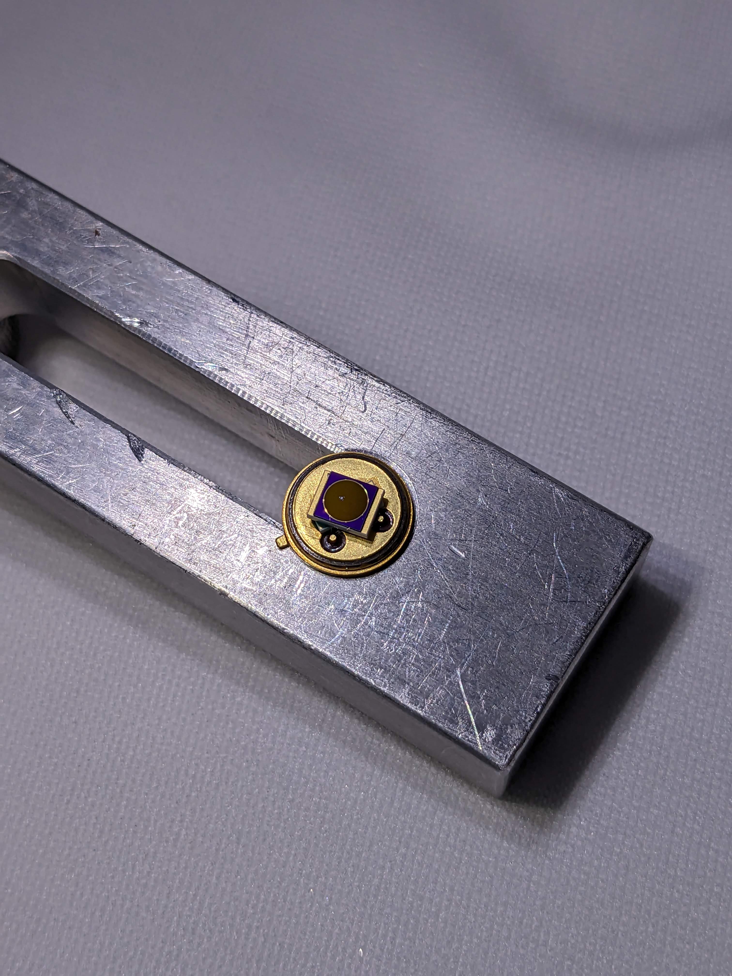
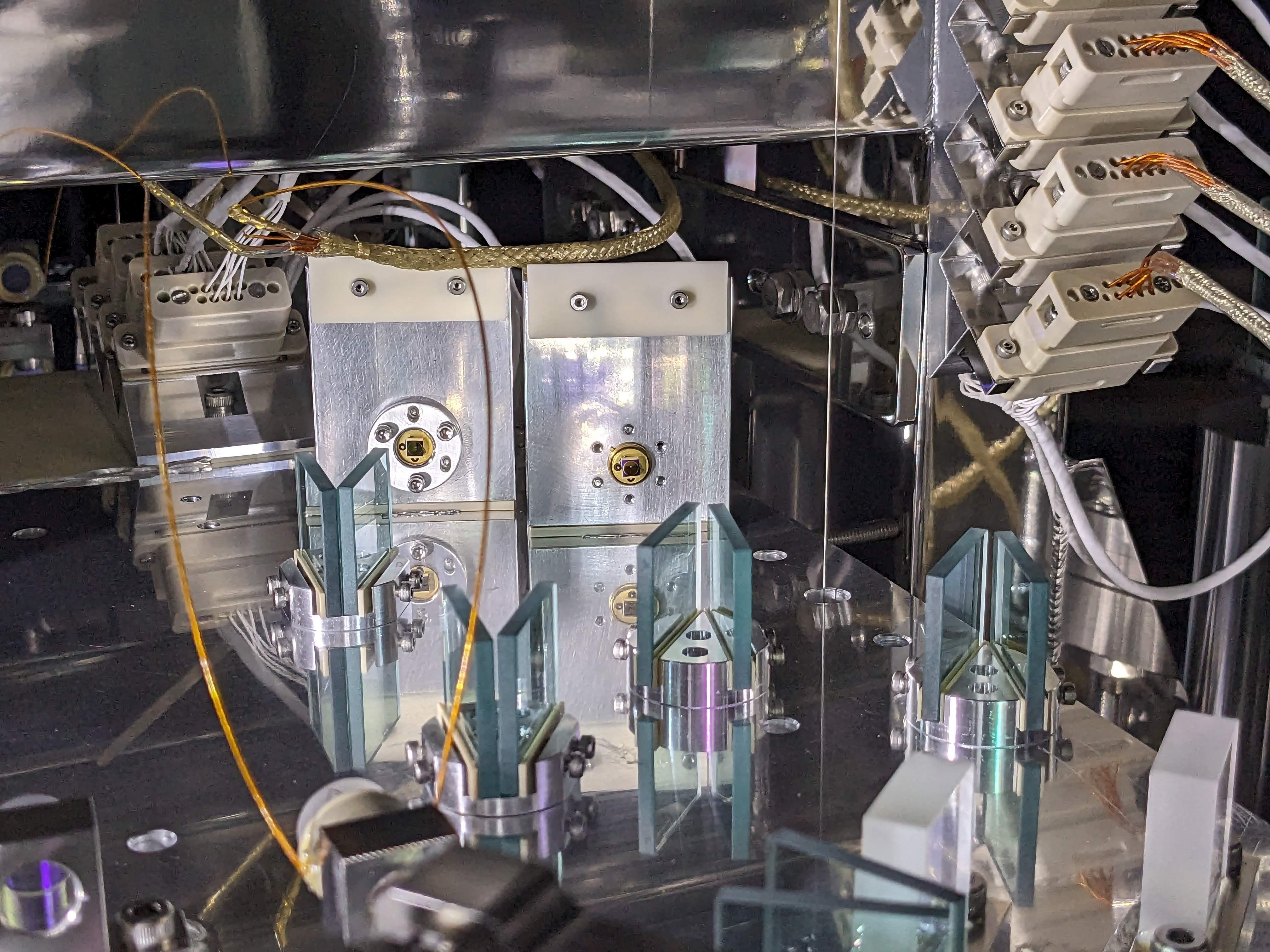
Actually, there is a similar white spot on the PDA too.
Images attached to this report
Non-image files attached to this report
Comments to this report:
yoichi.aso - 21:15 Tuesday 17 October 2023 (27234) Print this report

Takahashi, Aso

Summary

We replaced the two DCPDs successfully.
Both PDs respond to laser pointer illumination.
The dark noise spectra are as good as the original PDA.

Details

Initial failure

After yesterday's failure of the PD replacement, I opened another PD can much more carefully, spending more than 1.5 hours.
We inserted the diode to the holder, without closing the lid.
Then checked if the PD responds to a laser pointer at this stage.
It did. So we put a lid on the diode and tightened the screws.
After that, we checked the PD response again. This time, the PD showed no signal.
So, closing the lid somehow broke the PD

Cause of the failure

Here is our theory of how the PD died.
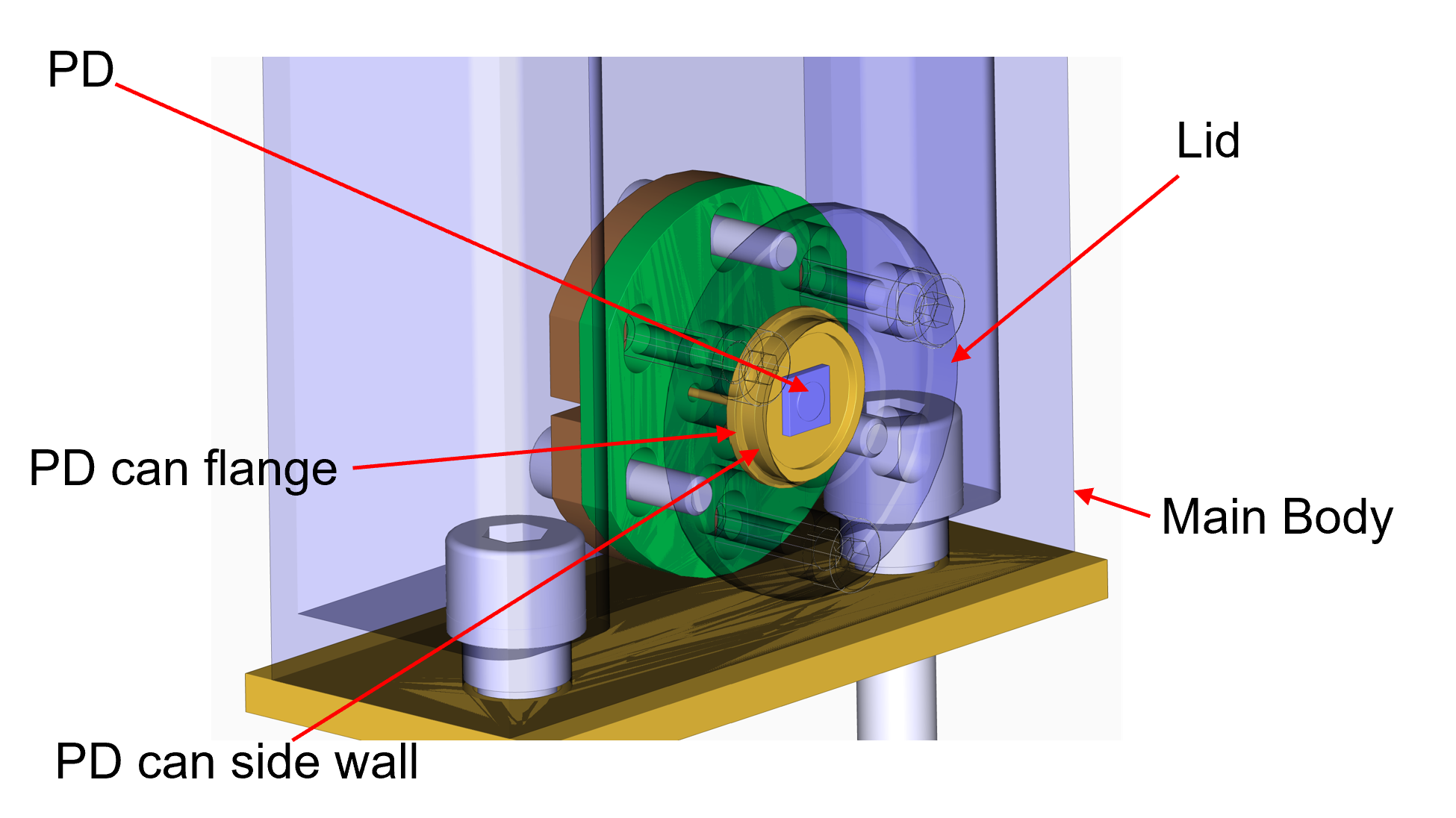
As shown in the figure below, the lid pushes the PD can on its flange to press the PD against the main body. There, the side wall of the PD can is supposed to fit in the central hole of the lid. However, it is a tight fit.


When assembling the PD holder by itself, it was easy to make sure that the side wall fits well in the hole. However, during the in-situ replacement of the PD, it was very difficult to make sure this, because the holder is upright and the access to it is severely limited. Therefore, there is a good chance that the lid crashes a part of the side wall when the screws are tightened. This can put a strong stress in the diode elements and damage them.


Solution

Since it is almost impossible to nicely align the PD can side wall and the tight hole of the lid, we decided not to put the lid after the PD replacement.


In this case, the diode is held by the three legs inserted into contact pins. They are sufficiently tight and it takes some effort to remove the PD. So I don't worry about the mechanical stability.

Ushiba-kun raised a question about the thermal conductivity between the PD and the holder.
It is a legitimate concern, since the PDs receive a few tens of mW each. 
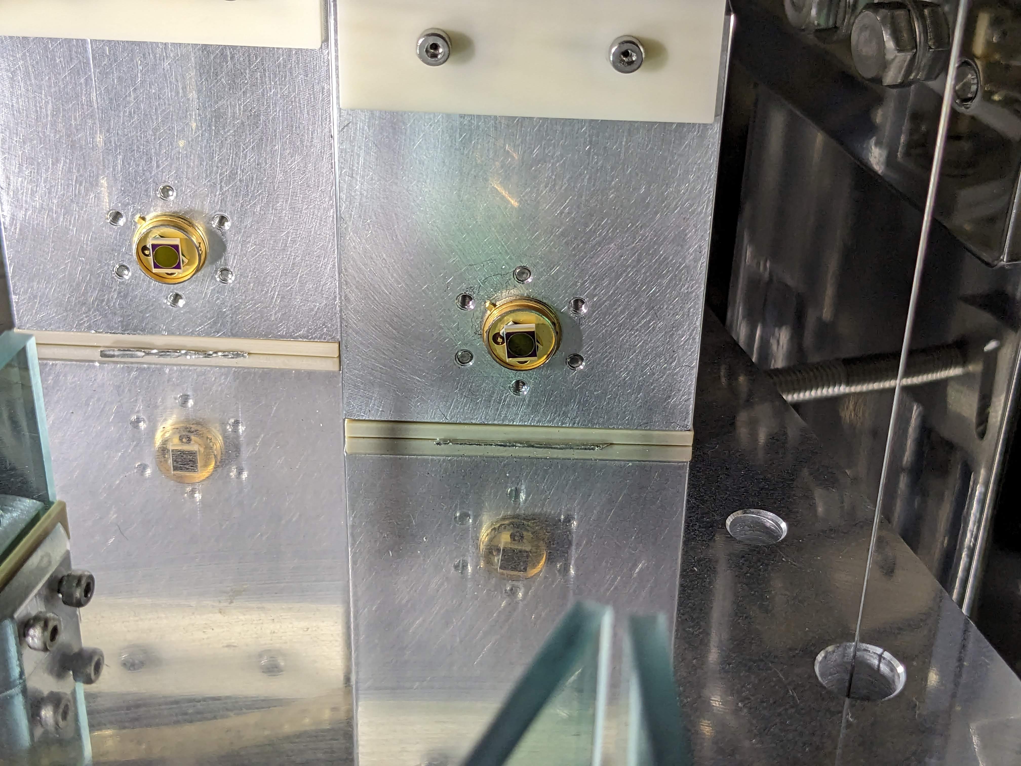
We don't have a definite answer to it. As shown in the photo, the PD can certainly contacts with the main aluminum body of the holder. However, the thermal conductivity is probably lower compared with when it is pressed by the lid.

Current state

For the moment, we left the PDs without the lids.
Both PDs respond to the laser pointer illumination.
The dark noise level is the same as the PDA noise before.
https://klog.icrr.u-tokyo.ac.jp/osl/uploads/27234_1697544797_DCPD-Noise-After-Replacement.pdf

We will unlock the OMC bread board and try to lock the OMC tomorrow to confirm the performance of the PDs.

Images attached to this comment
Non-image files attached to this comment
tomotada.akutsu - 7:04 Wednesday 18 October 2023 (27236) Print this report

Guessing several side effects or senarios due to OMC DCPD damaging, and one of them would be as follows, maybe. Assume that the damage would reduce the photocurrent with respect to the same received light power. Then the DARM offset required to achieve the same amount of the DC output should increase along with the growing of the damage; a positive feedback. The increase of the DARM offset would increase several coupling coefficient from the other unwanted DoFs to the DARM sensitivity maybe, and then the DARM sensitivity might got wrose and worse...

yoichi.aso - 18:19 Wednesday 18 October 2023 (27245) Print this report

Akutsu, Takahashi, Aso

Summary

We replaced the in-vac cable for the DCPD to a new one.
We released the OMC.
We installed the bread board dampers.
The OMC alignment was recovered.
We confirmed that the OMC can be locked.
The OMC transmission was about 95%.

Details

Cable replacement

We replaced the in-vac cable connecting the feedthrough flange and the DCPD pre-amp with a new cable.

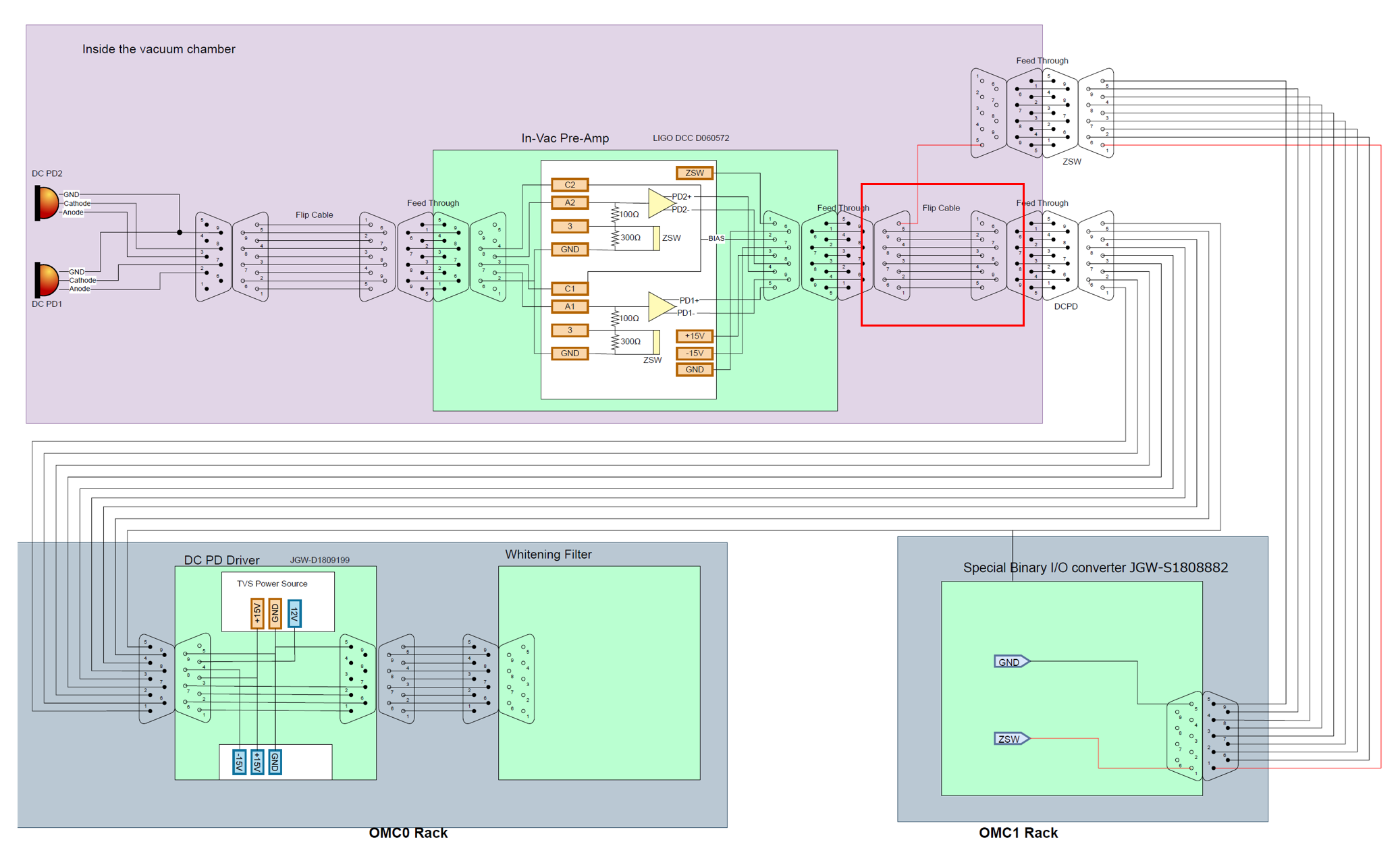
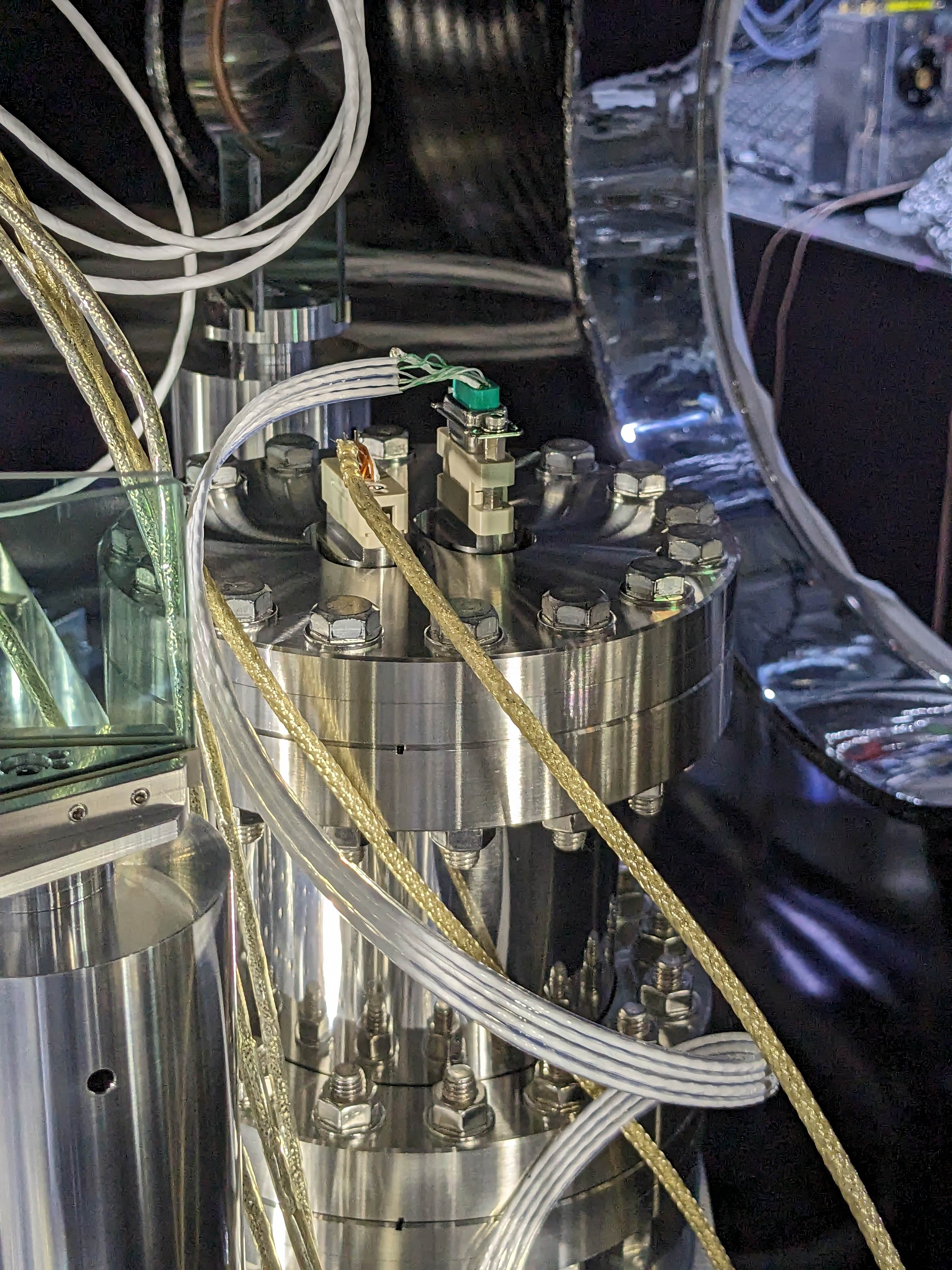
Old cabling configuration

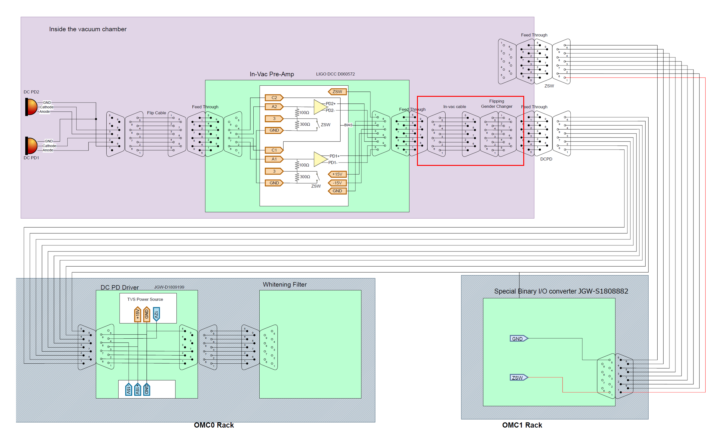
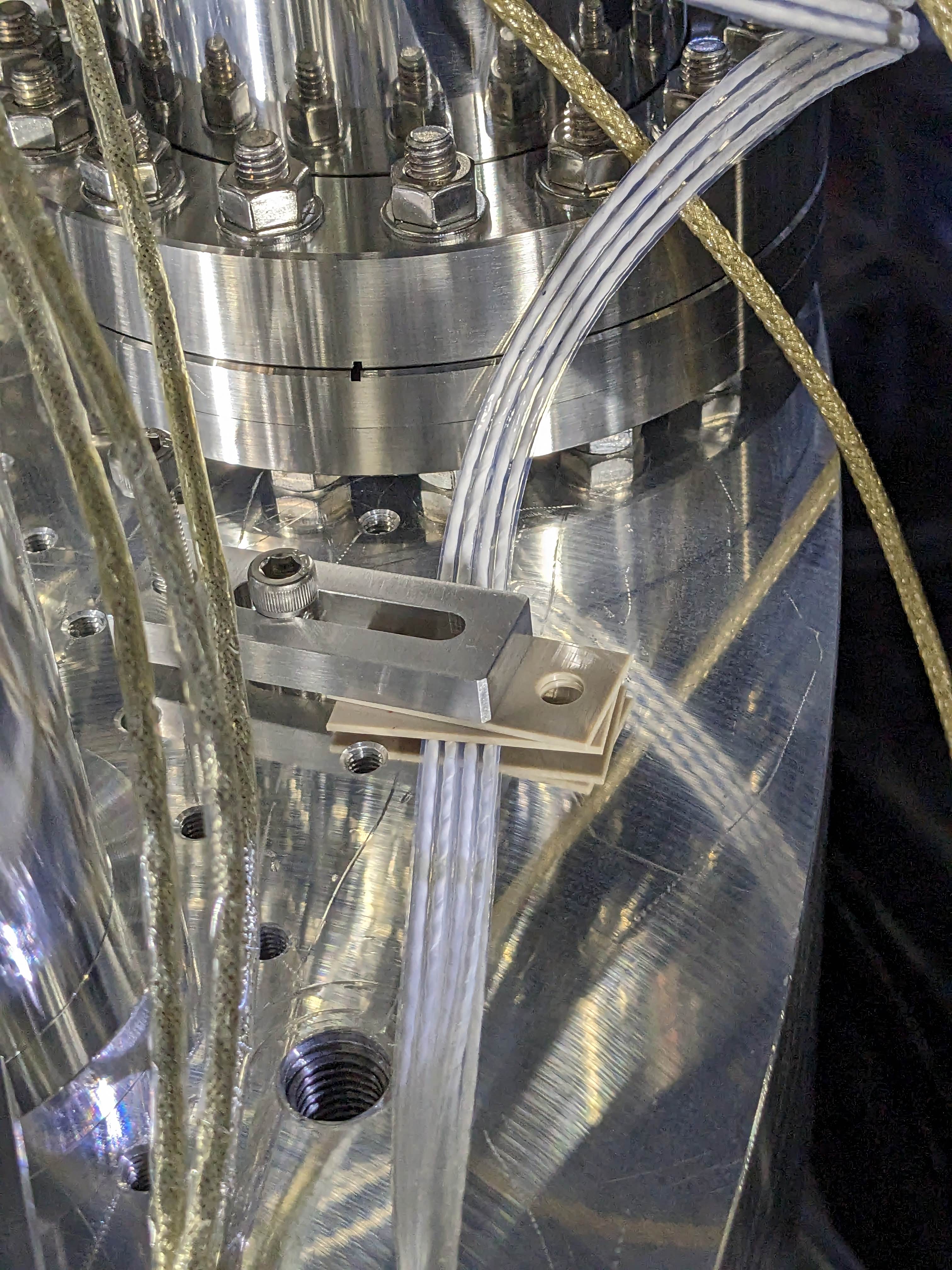
New cabling configuration

The white flat cable is the new cable. The brownish cables are original cables of OMC.

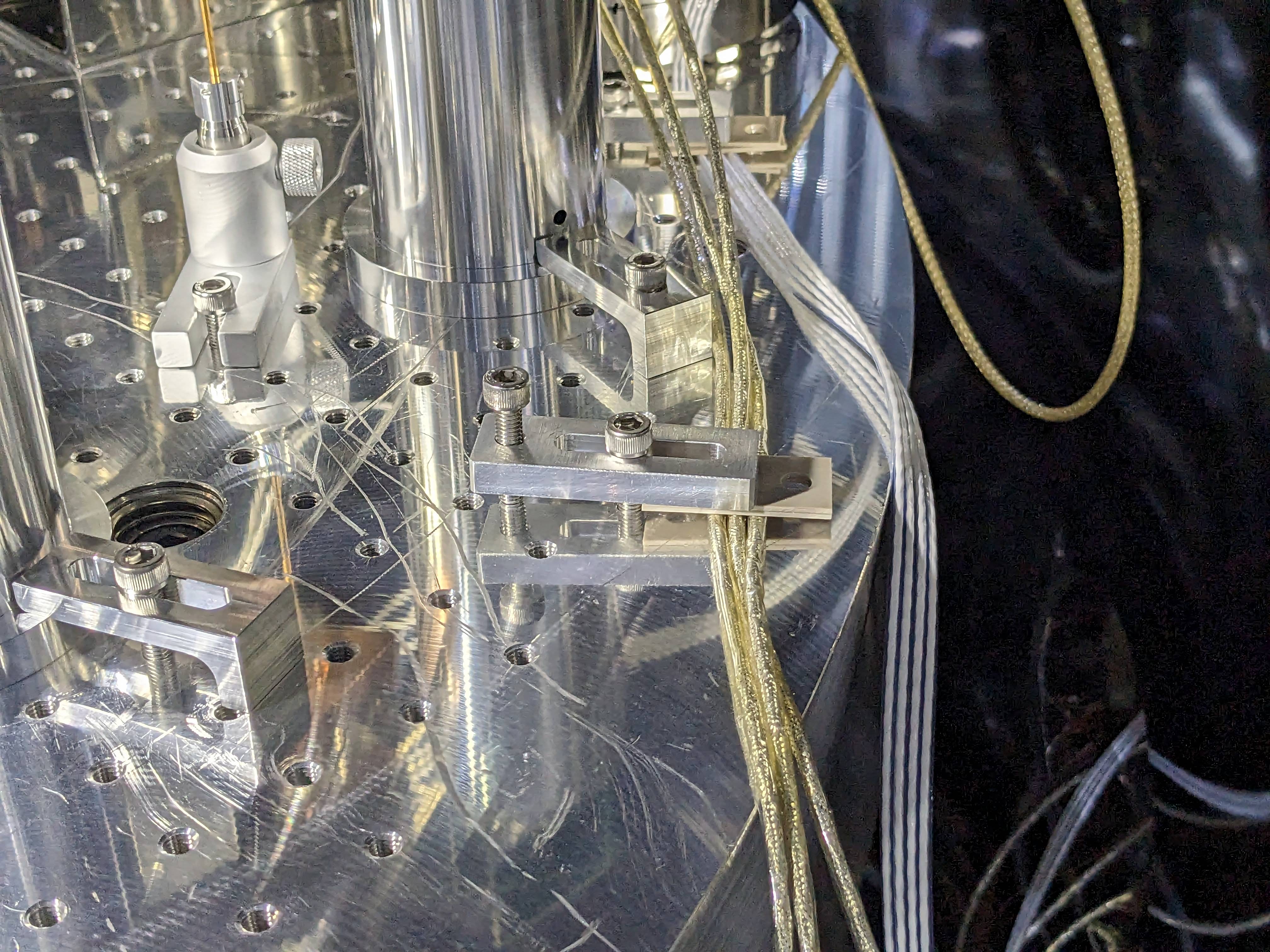
Fixing the cables

We anchored the OMC cables on the optical table, which is vibration isolated by a stack.

Installation of the bread board dampers

To be reported separately

OMC alignment recovery

After releasing the OMC suspension, we locked the interferometer in the single arm mode.
The IFO AS beam was hitting the OMC QPDs. So the OMC alignment had not been so much changed.

We used picomotors to center the OMMT2 transmission QPDs with OMMT1, then centered the OMC QPDs with OMMT2 and OSTM.

OMC lock confirmation

We first measured the input power to the OMC, just after the OFI, with a power meter. It was 36mW.

Then we closed all the doors of the chamber and turned off most of the cleanbooth filters leaving only one of them running.

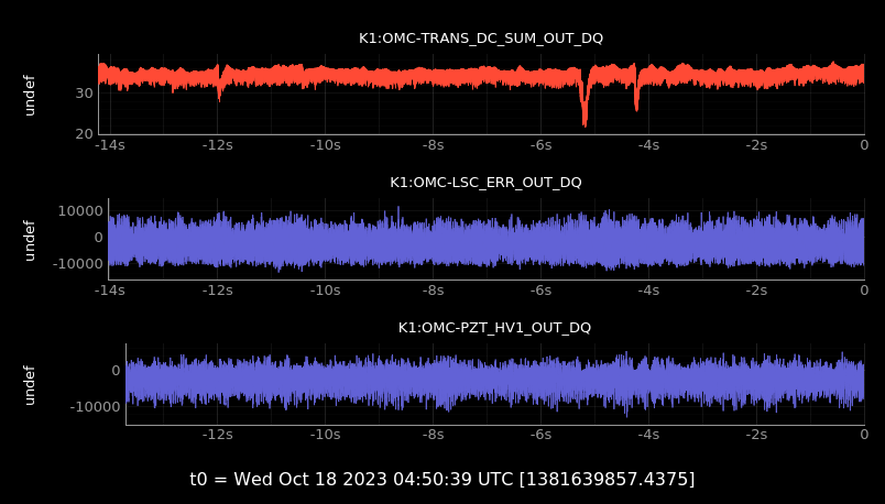
We then locked the OMC to TEM00 mode. The transmission power, using the same calibration factor as before the replacement of the PDs, was 34mW. Therefore, the transmissivity is about 95%.

Below are the spectra of the OMC LSC error and feedback signals.

https://klog.icrr.u-tokyo.ac.jp/osl/uploads/27245_1697620416_Spectra-All.pdf
https://klog.icrr.u-tokyo.ac.jp/osl/uploads/27245_1697620420_Spectra-Zoom.pdf


Images attached to this comment
Non-image files attached to this comment
Search Help
×

Warning

×