Reports 1-1 of 1 Clear search Modify search
VIS (SR3)
fabian.arellano - 17:04 Tuesday 10 January 2023 (23508) Print this report
F0 sensor correction filter.

Following H-infinity methods, I calculated the shape of the F0 sensor correction filter. I used the F0 LVDT noise and the upper limit of the seismic ground motion reported in klog 23507.

The description of the figures is as follows:

  1. LVDT noise transfer function model.
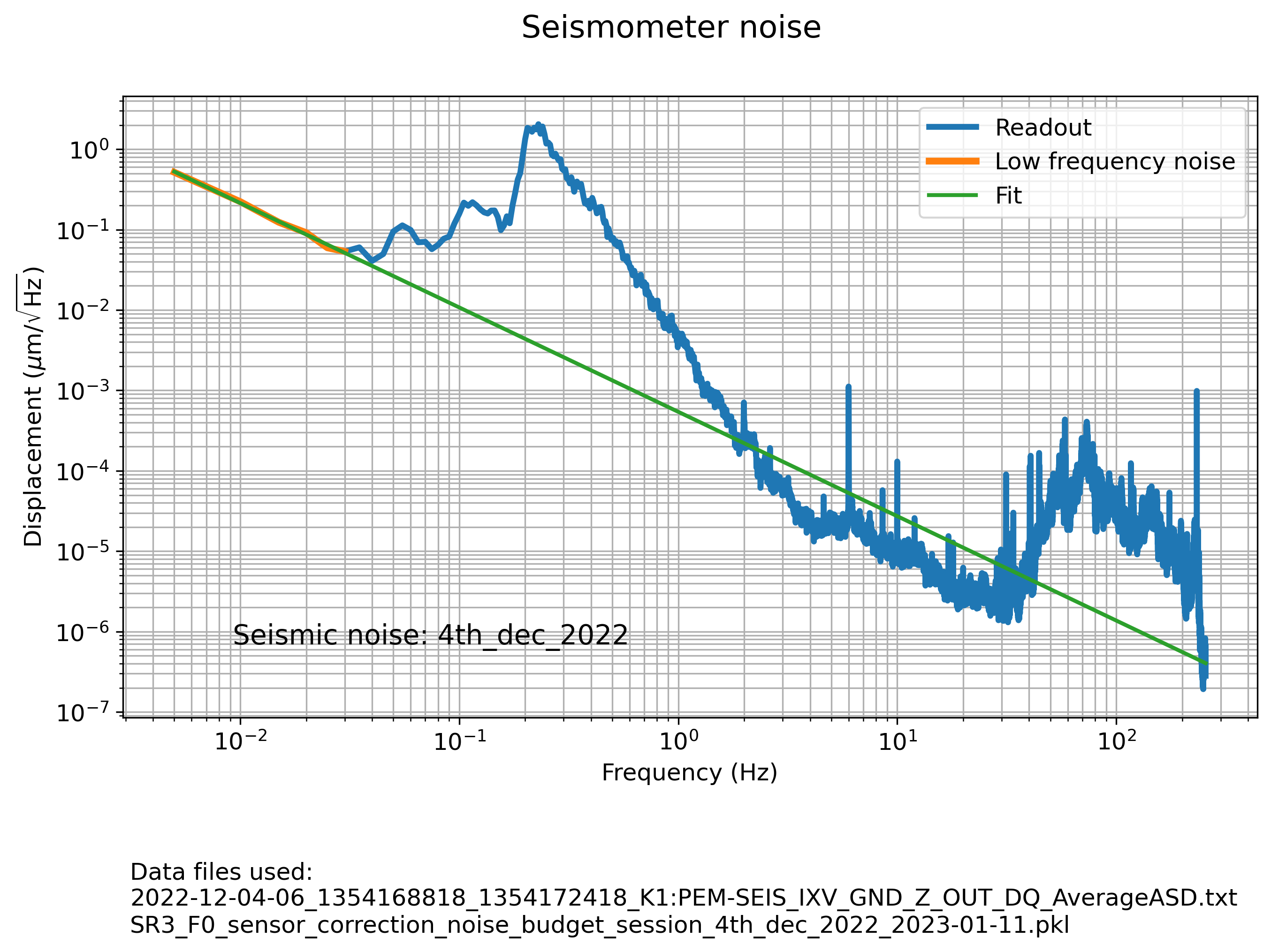
  2. Seismometer noise transfer function model.
  3. Seismic noise transfer function model. It also shows the seismic noise processed for the noise budget calculation.
  4. Sensor correction filter synthesis. It shows the noises, the optimized filters and the sensor correction noise.
  5. Calculated uncorrected and corrected LVDT noise.

As shown in Fig. 5, the improvement of the corrected LVDT noise, with respect to the uncorrected one, is a factor of 10.

The Foton expression of the sensor correction filter is:

zpk([0.000467+i*0.000831;0.000467+i*-0.000831;0.00587388;0.003640+i*0.040495;0.003640+i*-0.040495;0.051338;0.046736+i*0.047732;0.046736+i*-0.047732;0.0866736;0.015139+i*0.097614;0.015139+i*-0.097614;0.152978;0.463531;1.87951;3.2481;2.87574e+06],[0.00135789;0.015222;0.003709+i*0.039889;0.003709+i*-0.039889;0.024955+i*0.046410;0.024955+i*-0.046410;0.050455+i*0.021623;0.050455+i*-0.021623;0.087169;0.011033+i*0.096770;0.011033+i*-0.096770;0.150737;0.463531;1.8852;3.2481;2.89285e+06],0.00748886,"n")

For my own reference, the session file name is SR3_F0_sensor_correction_synthesis_upper_limit_2023-01-10.pkl. I'll upload the Jupyter notebooks and data files later after the sensor correction campaign is finished.

The filter has not been written in any filter bank yet.

Images attached to this report
Comments to this report:
tatsuki.washimi - 21:28 Tuesday 10 January 2023 (23514) Print this report

Are you using the seismometer on IXV (Trillium 120)?

Your empirical model for the seismometer noise shows ~10 um/rtHz @ 1e-2 Hz (~0.6 um/s/rtHz), but we know our seismometer signal is down to ~0.1 um/s/rtHz in a quiet condition. (for example, 2020-06-10)

So the component below 4e-2Hz in your plot is not a sensor noise but an actual seismic motion. You can set the noise model smaller if it is worth doing it. 

Non-image files attached to this comment
fabian.arellano - 10:00 Wednesday 11 January 2023 (23525) Print this report

The low frequency noise, shown in Fig. 2, is indeed not only seismometer noise. It does change with the seismic conditions and, therefore, it has a contribution from the ground motion itself.  Whatever their contributors are, we still need to minimize its influence on the corrected LVDT, which is what the optimization procedure does. In future posts, I should change the name of this contribution in order to avoid misunderstandings.

It's interesting to point out that, according to Miyo-kun's experience, seismometers of this kind do not show coherence below 40 mHz even if they are placed close together. This suggests that even if such a noise has a contribution from the ground motion, the seismometer still does not provide a reliable estimate of the ground motion at those frequencies.

fabian.arellano - 13:06 Wednesday 11 January 2023 (23528) Print this report

The sensor correction filter, reported in entry 23508, was designed using an upper limit of the microseismic motion (see 23507). It's fair to ask how such a filter would perform in different conditions, in case it's necessary to change its design. In this entry, I report the calculated noise of the corrected LVDT when the amplitude of the ground motion is low.

I used the ASD measured on the 28th of June 2022, when the secondary microseismic peak reached 0.25 um/rtHz approximately. The description of the figures is as follows:

  1. Low frequency noise empirical model (includes seismometer noise and ground motion too).
  2. Seismic noise, modified at low frequencies to be able to use it in the noise budget calculation.
  3. Noise budget calculation.

As can be seen in Fig. 3, the reduction of the rms noise of the LVDT is a factor of 4.4, integrated from 10 to 0.006 Hz, and the reduction of contribution of the secondary microseimic peak is substantial

The calculation suggests that using this sensor correction filter, in these low amplitude seismic conditions, is not harmful for the performance, and it's even beneficial. It's worth pointing out that in these conditions, the ground motion is not expected to be a problem for the interferometer alignment even when the LVDT is not corrected.

Images attached to this comment
fabian.arellano - 13:11 Wednesday 11 January 2023 (23529) Print this report

The sensor correction filter, reported in entry 23508, was designed using an upper limit of the microseismic motion (see 23507). In this entry, I report the calculated noise of the corrected LVDT when the ground motion has a midsize amplitude.

I used the ASD measured on the 4th of December 2022, when the secondary microseismic peak reached 2 um/rtHz approximately. The description of the figures is as follows:

  1. Low frequency noise empirical model (includes seismometer noise and ground motion too).
  2. Seismic noise, modified at low frequencies to be able to use it in the noise budget calculation.
  3. Noise budget calculation.

As can be seen in Fig. 3, the reduction of the rms noise of the LVDT is a factor of 19, integrated from 10 to 0.006 Hz, and the reduction of the contribution of the secondary microseismic peak is also substantial.

Based on this result, and the one reported in entry 23528, it seems safe to use the sensor correction filter for all microseismic conditions.

Images attached to this comment
fabian.arellano - 17:13 Wednesday 11 January 2023 (23531) Print this report

In the context of the F0 LVDT correction using the seismometer on the ground, entries 2350823528 and 23529 report the calculated noise of the corrected LVDT under different microseismic conditions. The question we still need to answer is, how to experimentally confirm these theoretical calculations. Here, a way to do it, is described.

In order to measure the corrected LVDT noise, from the corrected LVDT readout, we need to remove the displacement of the keystone quantified with respect to an inertial reference frame. We usually use the term GEO to refer to this quantity, although we don't have a geophone for F0.  The usage of this term comes from the IP, where we also use the sensor correction technique. Following entry 22998,

GEO = a × SEIS + LVDT,

where a is the inter-calibration factor, and SEIS and LVDT are the seismometer and uncorrected LVDT readouts. We can write this expression as,

GEO = [ 1 + LVDT / (a × SEIS) ] × a × SEIS,

where the ratio LVDT / (a × SEIS) is a transfer function we have measured before in the context of the inter-calibration factor calculation (see entries 23093 and 23124). Then, the noise N of the corrected LVDT can be written as,

N = LVDTc - GEO = LVDTc - [ 1 + LVDT / (a × SEIS) ] × a × SEIS,

where LVDTc is the corrected LVDT readout.

The noise N could be measured with a simple modification of the real-time model and medm screen. In a filter bank, we can write the mathematical model of the expression  [ 1 + LVDT / (a × SEIS) ] , then multiply it by the seismometer output a × SEIS, and finally subtract it from the corrected LVDT readout LVDTc.

fabian.arellano - 13:30 Thursday 12 January 2023 (23546) Print this report

I uploaded the sensor correction filter and the inter-calibration factor in the corresponding filter bank.

The filter reported in klog 23508 had a real zero and a real pole at 2.87574e+06 and 2.89285e+06 Hz respectively. I had to remove them by hand for Foton to accept the filter. Because these frequencies are very high, this change is not expected to have any impact on the performance.

The inter-calibration factor (see 23124) and the sensor correction filter were written in the SR3_F0_SENSCORR_GAS filter bank, and the integrator was left in the bank SR3_PEM_SEISINF_Z. In more detail:

  • Filter bank: SR3_F0_SENSCORR_GAS.
    • MEDM window: SENSCORR
    • FM1: intercalibration factor, intercal.
    • FM2: sensor correction filter, senscorr.
  • Filter bank: SR3_PEM_SEISINF_Z.
    • MEDM window: SEISINF.
    • FM7: integrator, vel2disp.

Characterization of the corrected LVDT perfomance still has to be done.

Also note:

  • Guardian turns on the sensor correction filter when the suspension goes through ENGAGE_STRONGDAMP state, along with the sensor correction for the IP.
  • The integrator was called m/s2m, which was a confusing name because we are working in micrometers. Therefore, I remaned it vel2disp, which stands for "velocity to displacement".
  • In the filter bank  SR3_PEM_SEISINF_Z there were three other filters that I removed: they were called HP (butter("HighPass",4,0.0005)) , intercal (gain(0.04168)) and AC (old sensor correction filter designed by Terrence for SRM IP).
fabian.arellano - 15:11 Friday 13 January 2023 (23562) Print this report

Here is a sketch of the simple addition to the real-time model, needed for measuring the corrected LVDT noise in real time.

The function T is the transfer function LVDT / (a × SEIS) referred to in klog 23531.

Images attached to this comment
fabian.arellano - 16:37 Friday 13 January 2023 (23565) Print this report

I corroborated that removing the zero and pole at high frequencies, using Foton, didn't have any impact in the other features of the filter. The filter is:

zpk([0.000467+i*0.000831;0.000467+i*-0.000831;0.00587388;0.003640+i*0.040495;0.003640+i*-0.040495;0.051338;0.046736+i*0.047732;0.046736+i*-0.047732;0.0866736;0.015139+i*0.097614;0.015139+i*-0.097614;0.152978;0.463531;1.87951;3.2481],[0.00135789;0.015222;0.003709+i*0.039889;0.003709+i*-0.039889;0.024955+i*0.046410;0.024955+i*-0.046410;0.050455+i*0.021623;0.050455+i*-0.021623;0.087169;0.011033+i*0.096770;0.011033+i*-0.096770;0.150737;0.463531;1.8852;3.2481],0.00748886,"n")

The plot shows the sensor correction filter before and after removal, together with the seismic noise suppression filter, and the addition of both, which should equal to 1.

Images attached to this comment
Search Help
×

Warning

×