Reports 1-1 of 1 Clear search Modify search
VIS (SR2)
fabian.arellano - 16:52 Thursday 01 December 2022 (23095) Print this report
Intercalibration between the seismometer on the ground and the F0 LVDT.

I tried to calculate the intercalibration factor between the seismometer on the ground, and the F0 LVDT. However, given the current microseismic conditions, the LVDT does not seem to have enough sensitivity for this calculation.

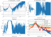
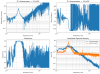
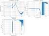
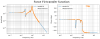
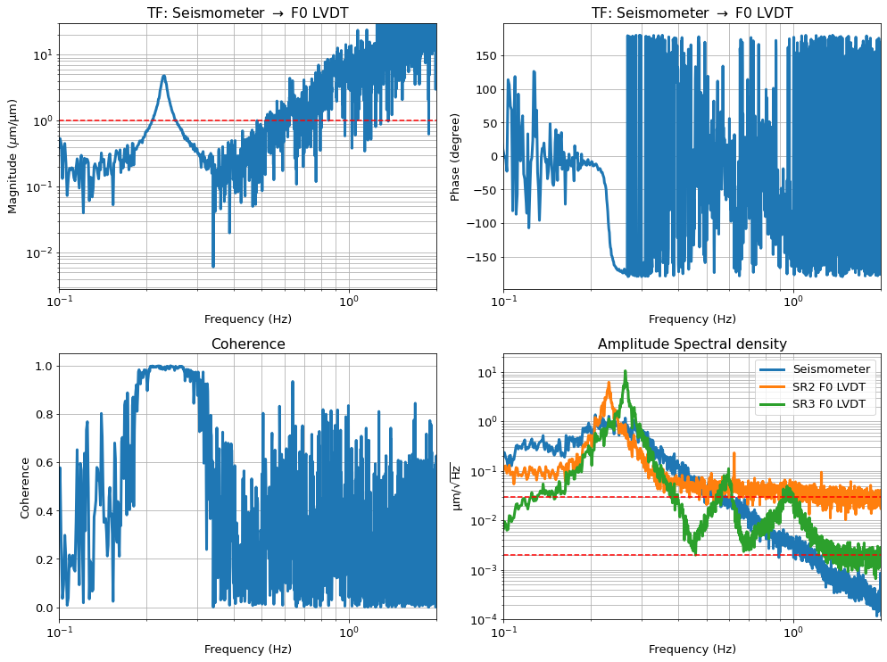
The figure shows the TF from the seismometer to the F0 LVDT, the coherence and the ASDs of the readouts of both devices. Additionally, the readout of the SR3 F0 LVDT is also shown for reference (see entry 23093). Such a spectrum was measured simultaneously as the ones for SR2.

As can be easily seen in the plots, the coherence is only high within a very narrow frequency band, and only one of the three expected peaks is visible. Therefore, it does not seem possible to follow the procedure outlined in klog 22998, and used as reported in klog 23093 for SR3. The transfer function is supposed to be close to unity at high frequencies, a value that is highlighted with a horizontal red line.

The limitation is the poor sensitivity of the SR2 LVDT. In the case of SR3, it was possible to calculate the intercalibration factor because its LVDT is more sensitive and the three peaks were clearly visible. Namely, above 1 Hz, the sensitivity of the SR3 LVDT is 15 times higher than that of SR2; the first one reaches 2 nm/rtHz, whereas the second one only 30 nm/rtHz. These levels are indicated with horizontal red lines in the figure.

This is information on the Jupyter notebook and diaggui file I used:

  • File name: seismometer_F0_lvdt_intercalibration.ipynb
  • Directory: /kagra/Dropbox/Subsystems/VIS/vis_commissioning/sr2/IP_diag/SENS_corre/Vertical/notebooks/
  • Conda environment: vishack.
  • Diaggui file: sr2_seis2f0_tf_ol_221130.xml
Images attached to this report
Comments to this report:
fabian.arellano - 16:49 Friday 02 December 2022 (23112) Print this report

I added to the plot of the amplitude spectral densities, the SR2 F0 LVDT readout measured for the acceptance check of the Type-B suspensions.

The noise level above 1 Hz was around 150 nm/rtHz and the suspension was in ALIGNED state. This is consistent with the level of 30 nm/rtHz measured recently in TWR_FLOAT state. The excess of noise must be due to injected noise by the control loop.

This is information on the acceptance check measurement:

  • Directory: /users/ryutaro/Log/220802/
  • File: SR2_spe3.xml
  • Date and time: 2022/08/02 at 01:48:48 UTC.
  • Guardian state: ALIGNED (Takahashi-san remembers).
Images attached to this comment
fabian.arellano - 15:52 Monday 05 December 2022 (23127) Print this report

Following the method outlined in klog 23124, I calculated the inter-calibration factor between the ground seismometer and the F0 LVDT.

The lack of data points in the displacement TF was compensated using the force TF.

  • Fig. 1 shows the displacement TF (also shown in klog 23095).
  • Fig. 2 shows the force TF measurement.
  • Fig. 3 shows the mathematical model fit to the force TF.
  • Fig. 4 shows the fit of the mathematical model, constructed with the force TF data, to the measured displacement TF.

In the latter fit, there are only three free parameters: the frequency and quality factor of the peak with the lowest frequency, and the amplitude a (per klog 23124 and other entries), which is the inter-calibration factor we are looking for.

The fit yields the value a = 1.1615.

I got the force transfer function data from the files listed in the health check report 20095.

Images attached to this comment
Search Help
×

Warning

×