w/ help fo Hirata, Yano, Miyoki; following 20616. Not yet completed but mostly done.
Summary of the situation
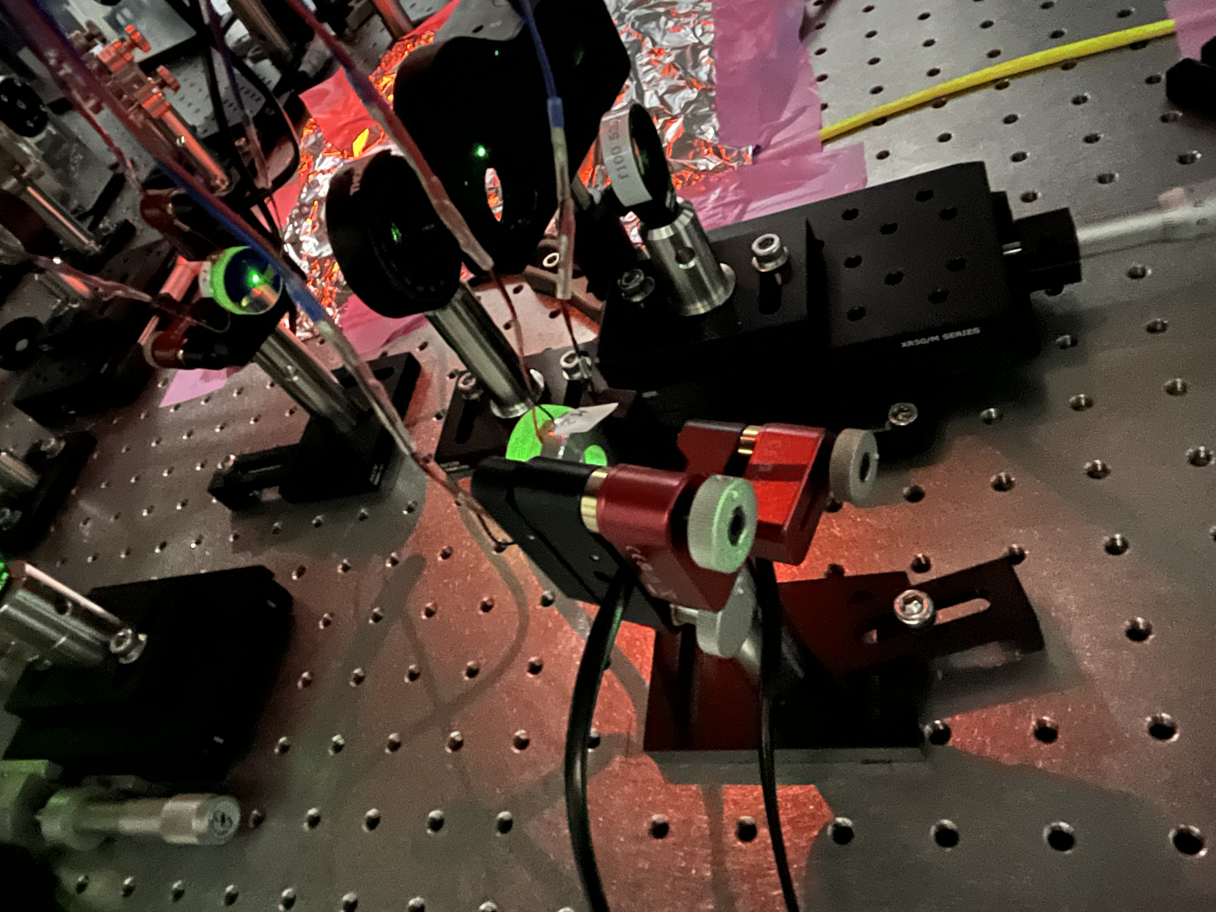
About the two pico-piezo steering mirrors on the POP table (those replaced in 17825),
- Connected the piezo wires to the relevant drivers; the drivers are not power supplied yet.
- Connected the picomotors to the driver lines that were rooted the other day (20920) by Nakagaki and Ikeda.
Piezo connectivity
- First, tha naming convention follows Fig. 6 of 17615; clock-wisely, 0, 120, 240 deg -> top, right bottom, left bottom from seeing HR of each mirror.
- 0, 120, 240 -> connected to X, Y, Z, respectively.
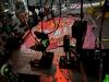
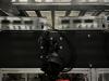
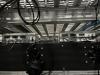
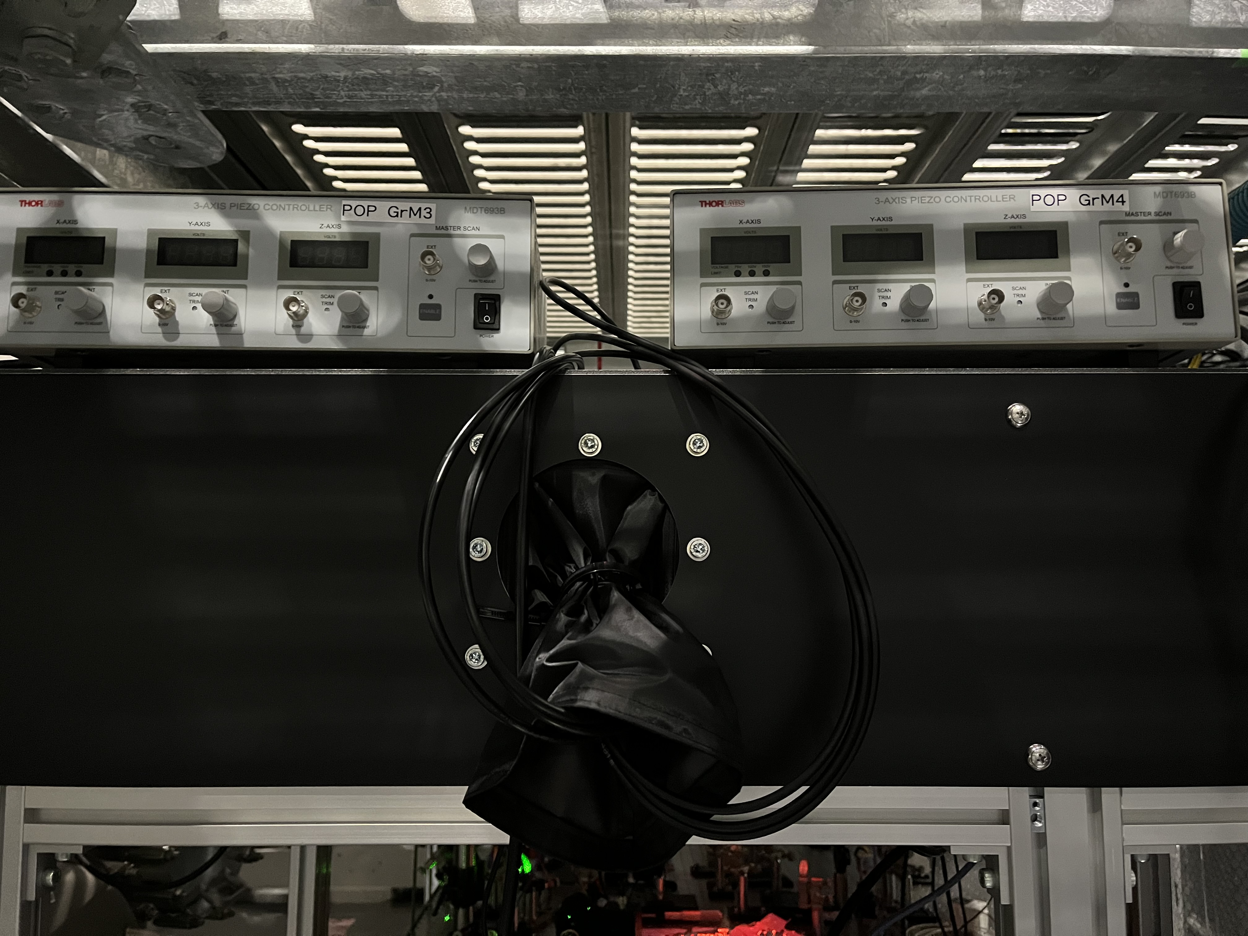
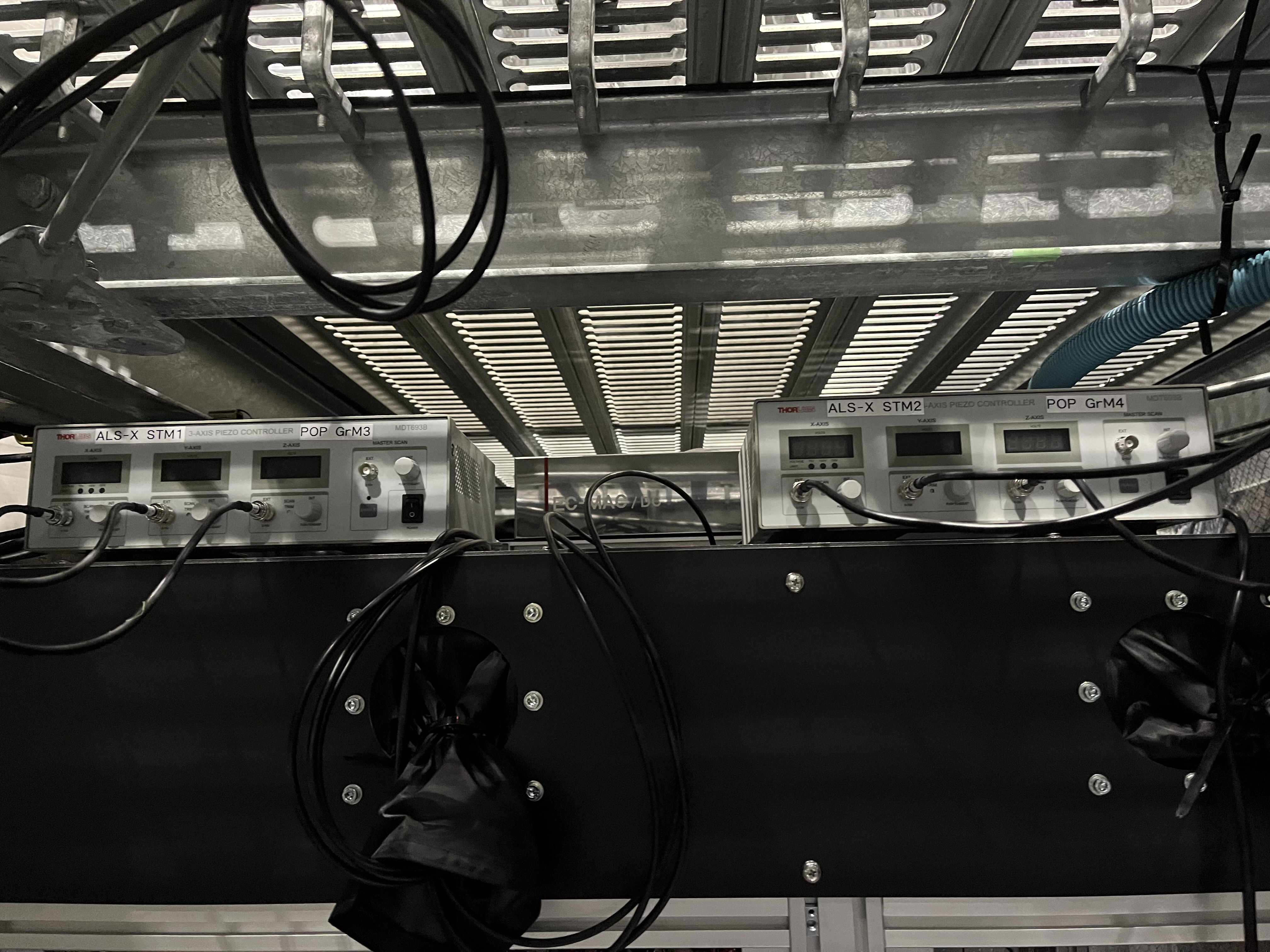
- The naming convention of the mirror at POP, I follow JGW-T2113048-v1, so the first one is POP GrM3 (Fig. 1), and the second one is POP GrM4 (Fig. 2), so the piezo drivers are labeled so (Fig. 3).
- Note that the power supply cables for these piezo drivers are not connected. And the inupt cables to the drivers are not connected yet.
Pico connectivity
- The above POP GrM3 -> POP1, GrM4 -> POP2.
