Uehara, K. Tanaka
[21.07.21 work]
We checked the operation of the PZT mirror we created yesterday (related to 17581). As it turned out, all the PZTs worked properly and the mirror could be tilted.
### What we did
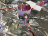
- First, we checked if the mirror was properly bonded to the PZT that we glued on yesterday. The glue seemed to be dry when we looked at it, and the cable attached to the PZT did not come loose when we pulled on it. (Fig. 1)
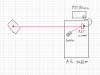
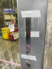
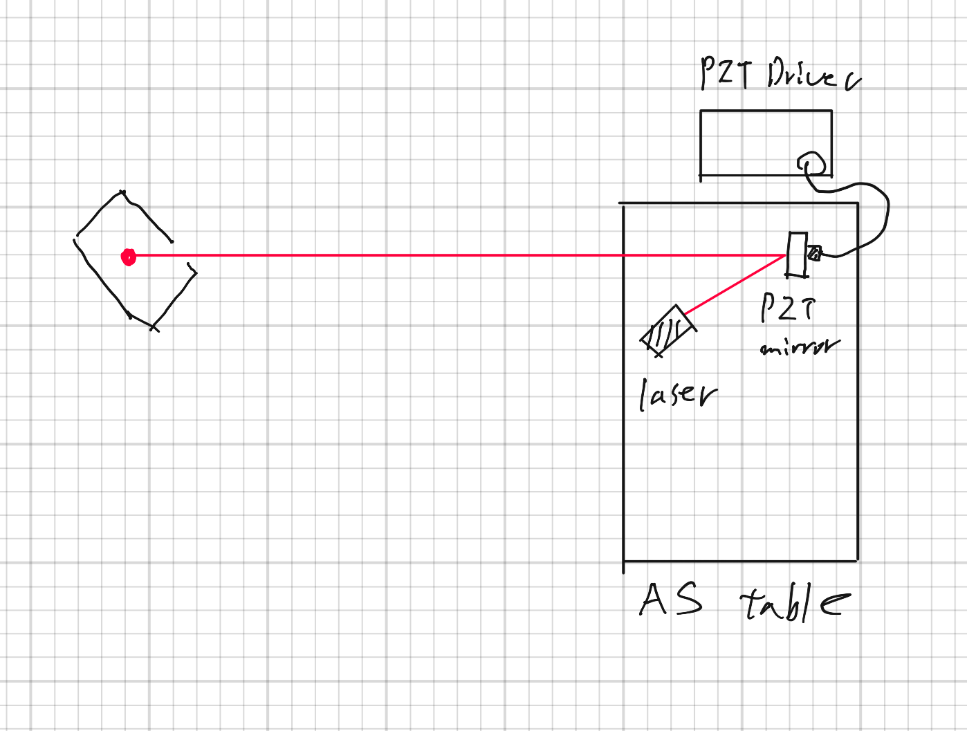
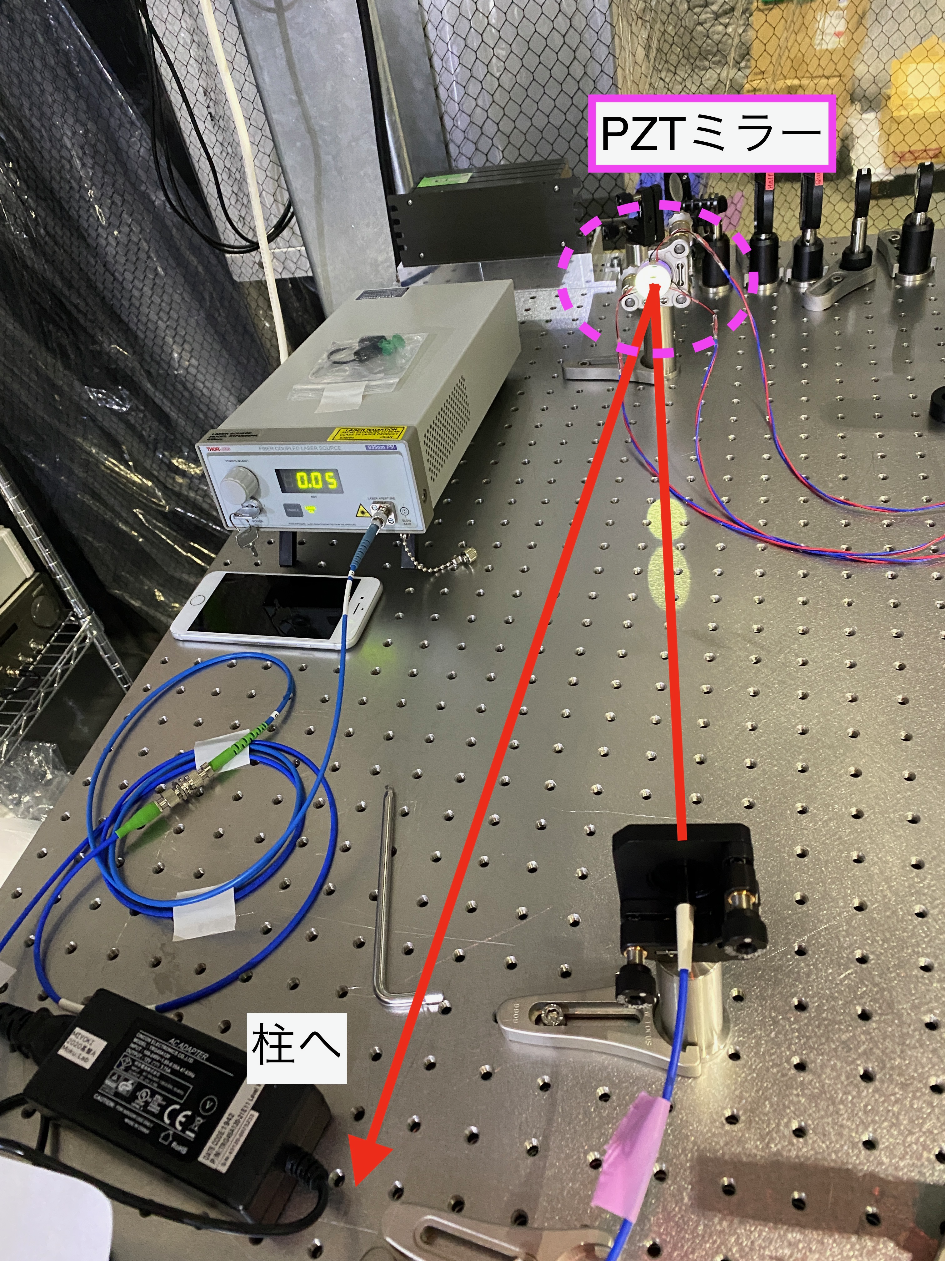
- Then, to see how the mirror tilts when a voltage is applied to the PZT, we created a setup like the one shown in Figure 2, using the available space on the AS optical surface plate. The light emitted from the light source is reflected by the PZT mirror and shines in a distant location. If we apply a voltage to the PZT and tilt the mirror, we can observe the beam spot moving. The actual setup is shown in Fig. 3, where the light bouncing off the PZT mirror is focused on a pillar in the AS clean booth. (Figure 4)
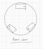
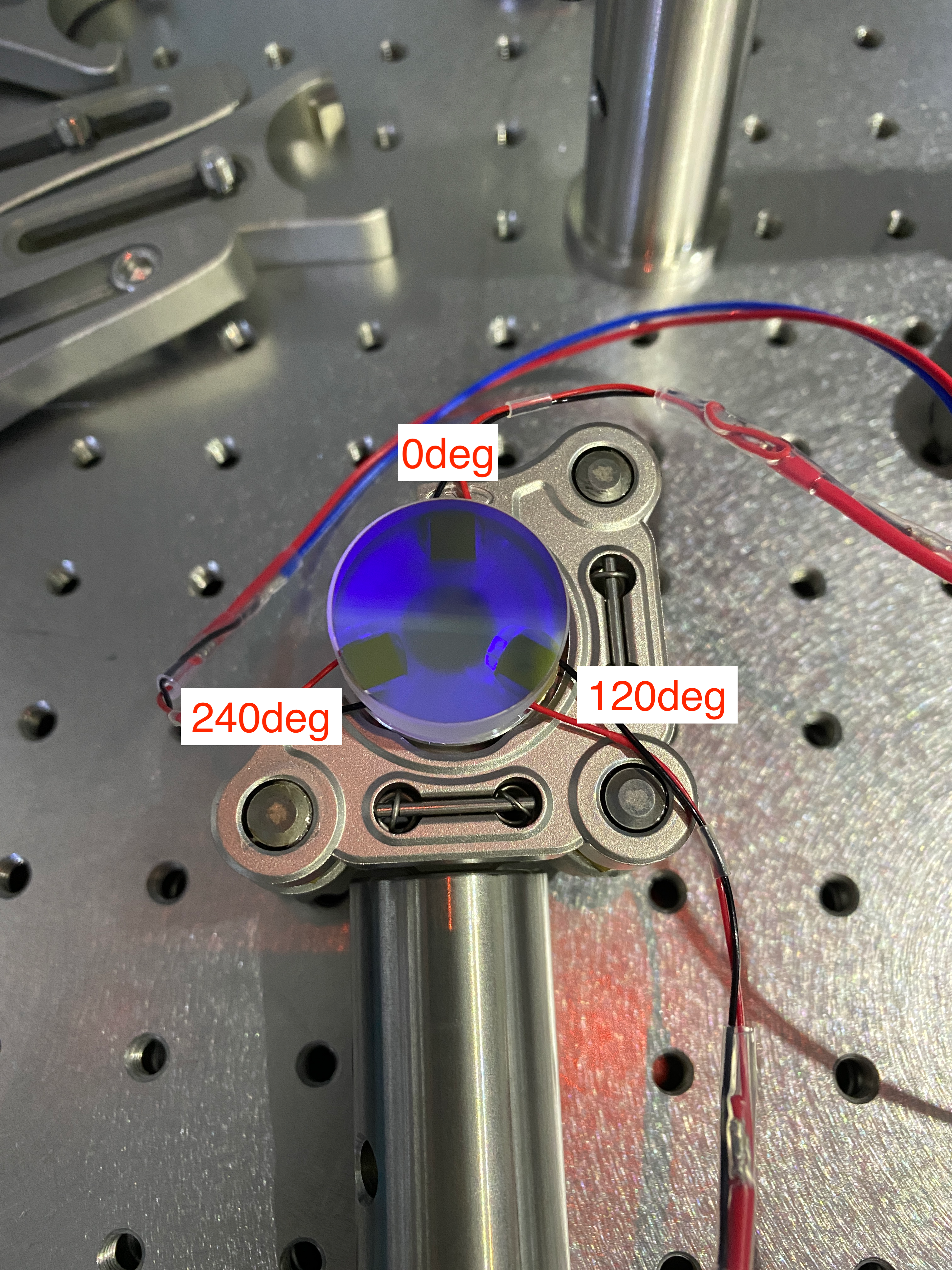
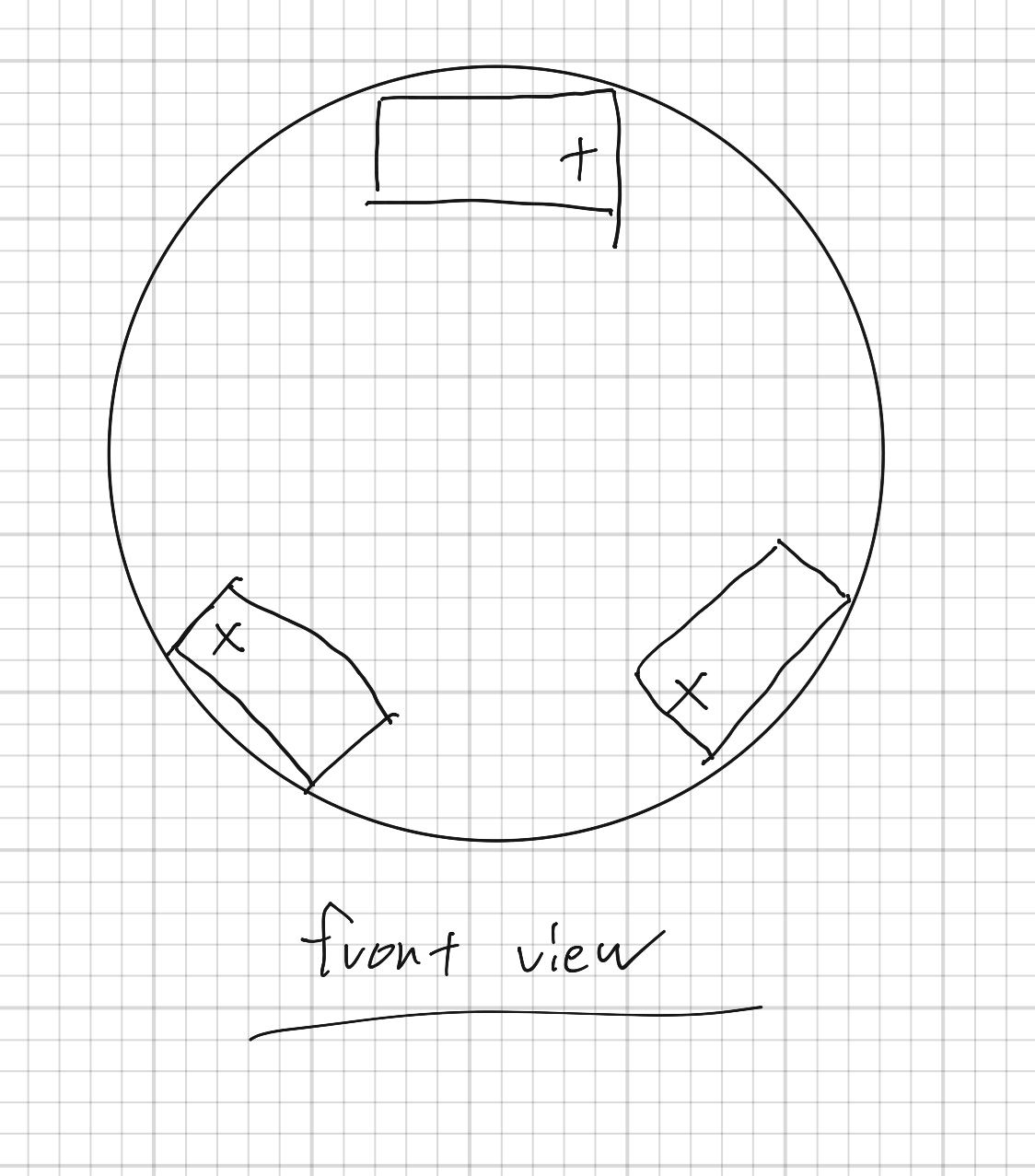
We also placed a ruler near the light so that we could measure to some extent how much the beam spot moved when the mirror was tilted. (Figure 5) - At this time, the PZT mirrors were placed on the mirror mounts as shown in Figure 6. We labeled each PZT mirror as 0deg, 120deg, and 240deg clockwise from the top. Also, I forgot to mention yesterday that I placed the PZT mirror so that the + electrode of the PZT is clockwise when viewed from the front. (Figure 7)
- To check the operation, we followed the steps below.
- Connect one terminal of the PZT to the x-axis output of the PZT driver,
- turn the knob to change the DC offset of the PZT driver, and apply a voltage from 0V to 150V to the PZT.
- Check if the beam spot is moving between 0V and 150V.
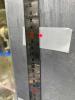
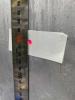
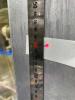
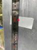
- The above procedure was performed in the order of 0deg->120deg->240deg PZT. According to Fig. 7, the beam spot should move almost perpendicular to the ground when the voltage is applied to 0deg PZT, right shoulder up direction when the voltage is applied to 120deg PZT, and right shoulder down direction when the voltage is applied to 240deg.
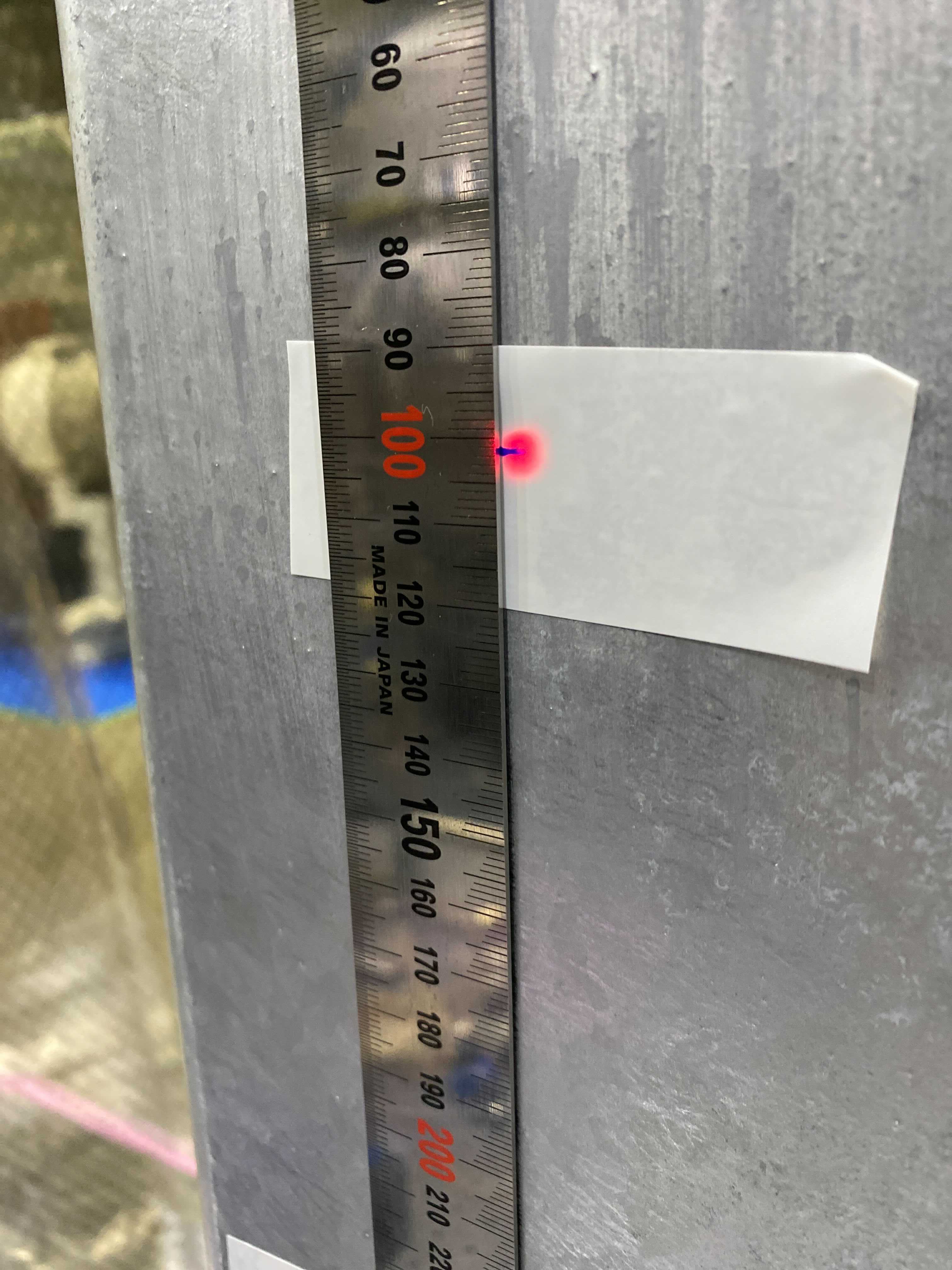
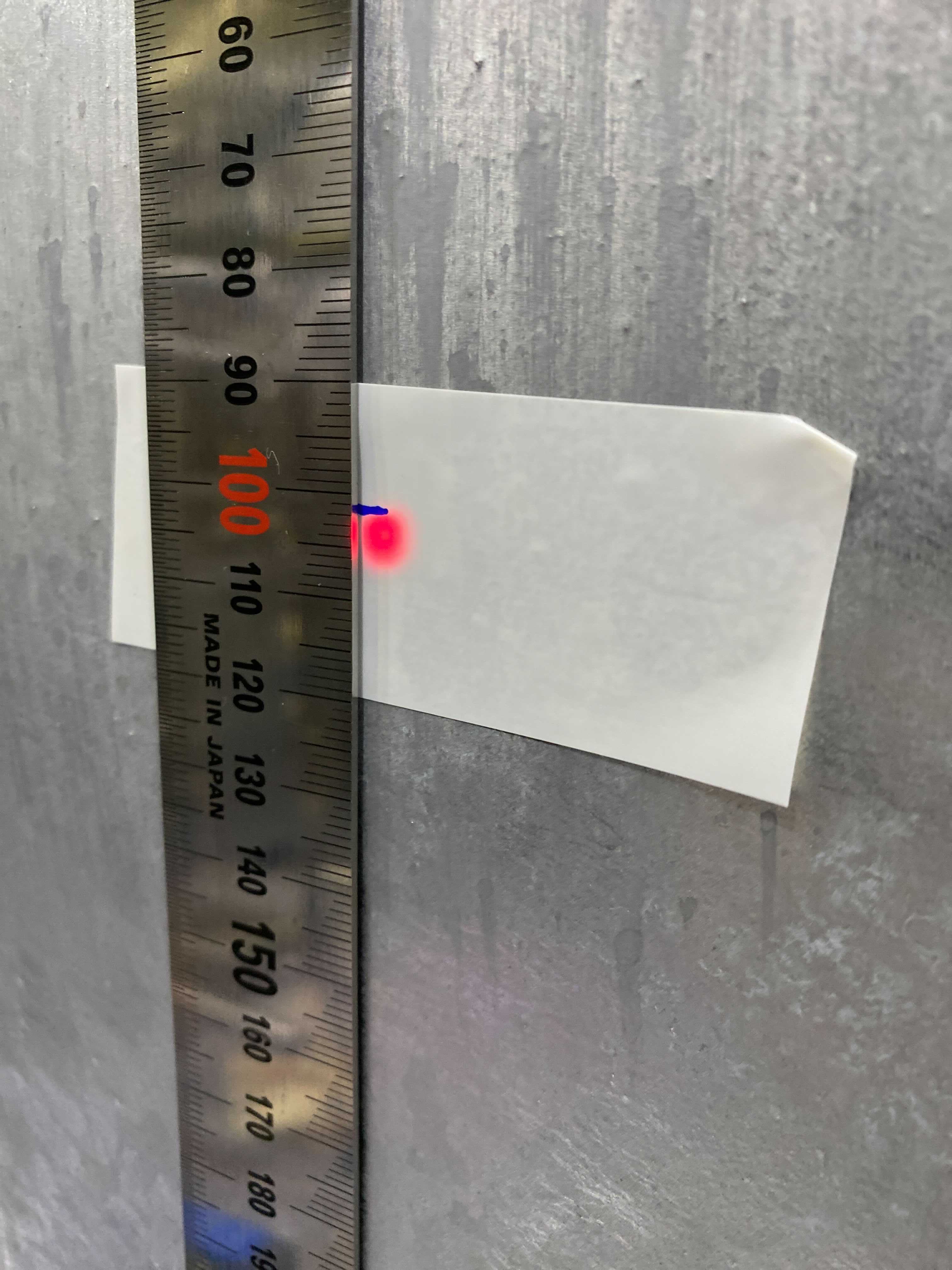
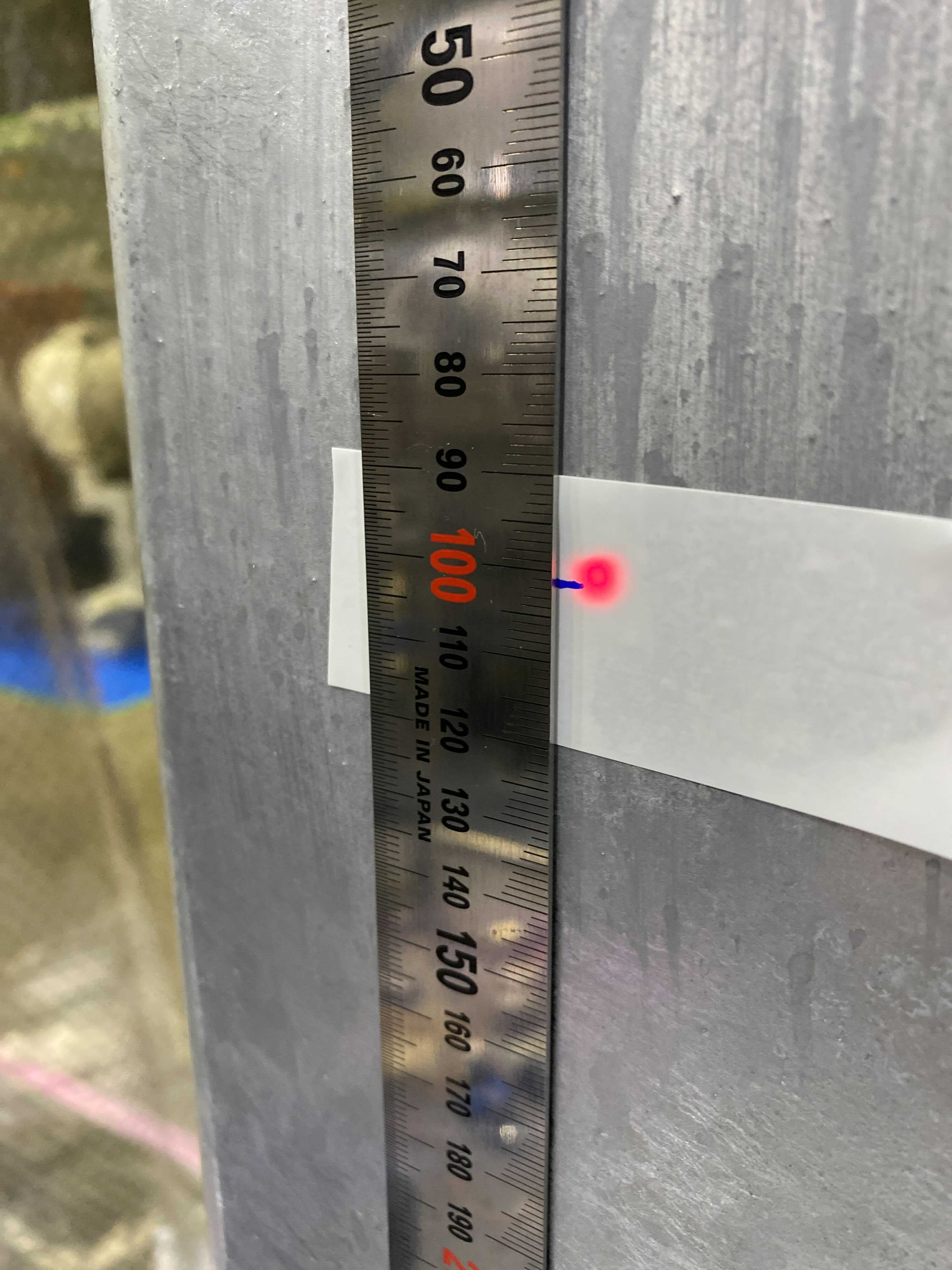
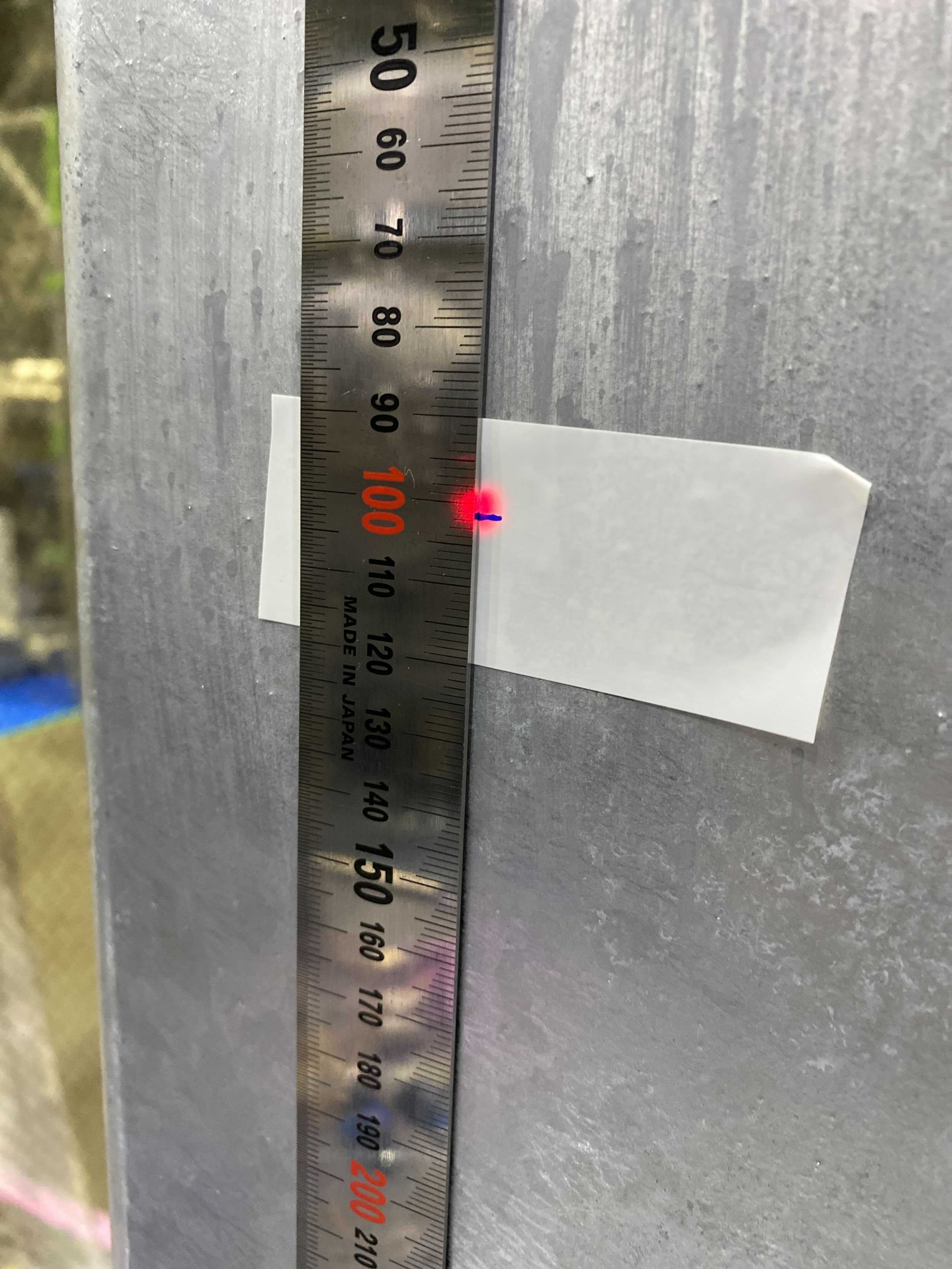
- Fig. 8 shows the position of the beam spot at 0V, and Figs. 9, 10 and 11 show the position of the PZT at 0deg, 120deg and 240deg when 150V is applied. Figures 9, 10, and 11 show the positions of the PZT at 0deg, 120deg, and 240deg when 150V is applied. A video recording of the process of applying voltage to the PZT at 0deg is attached. You can see that the beam spot moves as the voltage is applied to the PZT.
- These results show that the PZT is working properly. The above operation check was also performed on the other PZT mirror, and the same results were obtained.

.png)

.png)