Akutsu + Miyo + Ushiba, Tamaki; On 5 Aug 2021; Follow-up of 17770, 17819.
Abstract
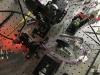
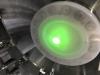
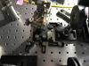
Replaced the two steering mirrors with the new PZT-pico mirrors on the POP table (Fig. 1). GreenX is not lost.
Confirming the mirror protrusion
In the new pzt-pico mirror assembly (see 17615, 17603), the mirror surface is stick out from the mirror holder in nominal 9 mm (Fig. 2). The contents are:
- Mirror 10D20DM.11: t6
- Piezo PA4FKW: t3
In the real world, the gluing layer may have a certain thickness, but which seems negligible for me. Anyway, it seems the baseplate of each old steering mirror should be pushed back in 9 mm.
Setting iris diaphragms
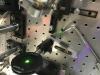
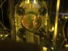
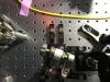
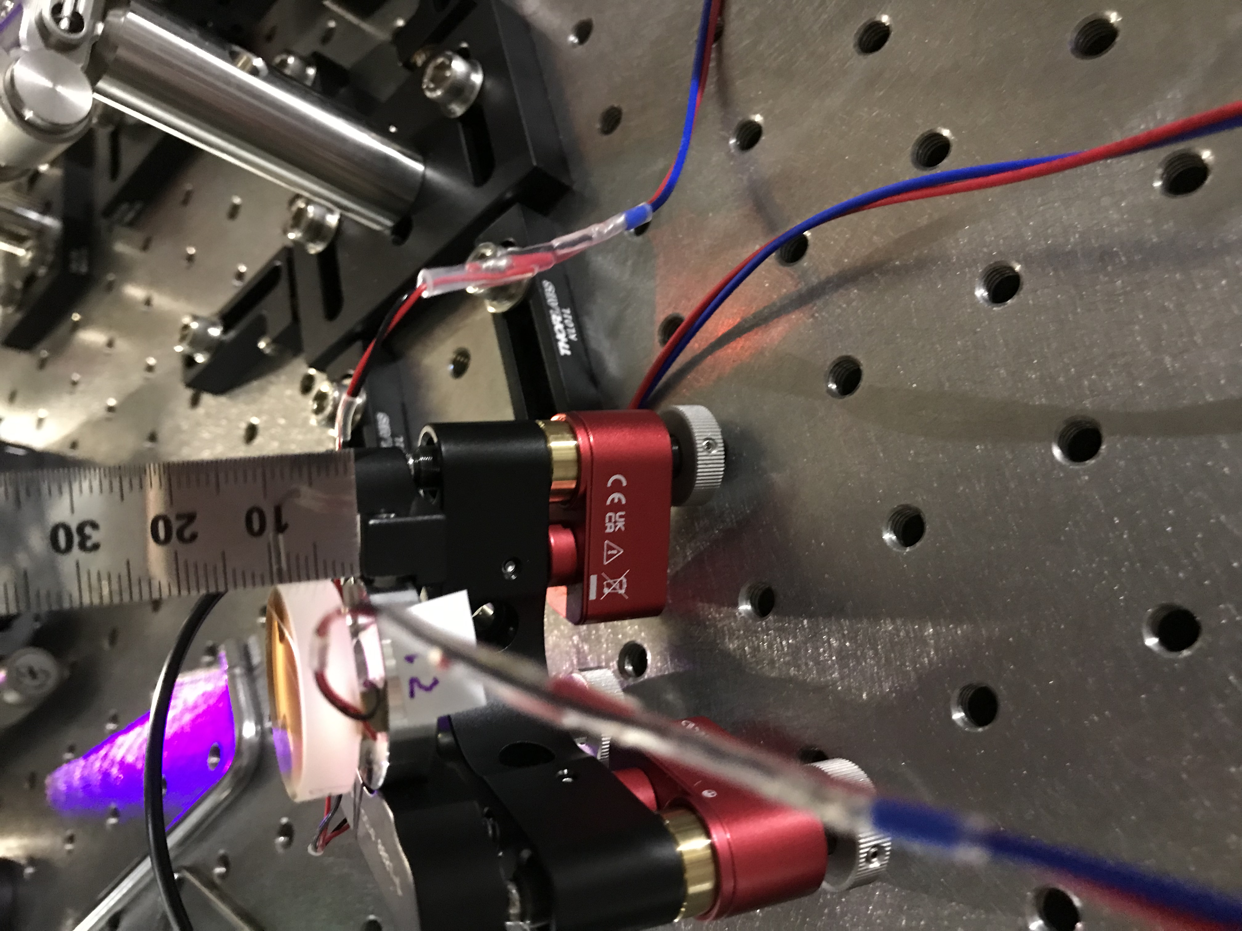
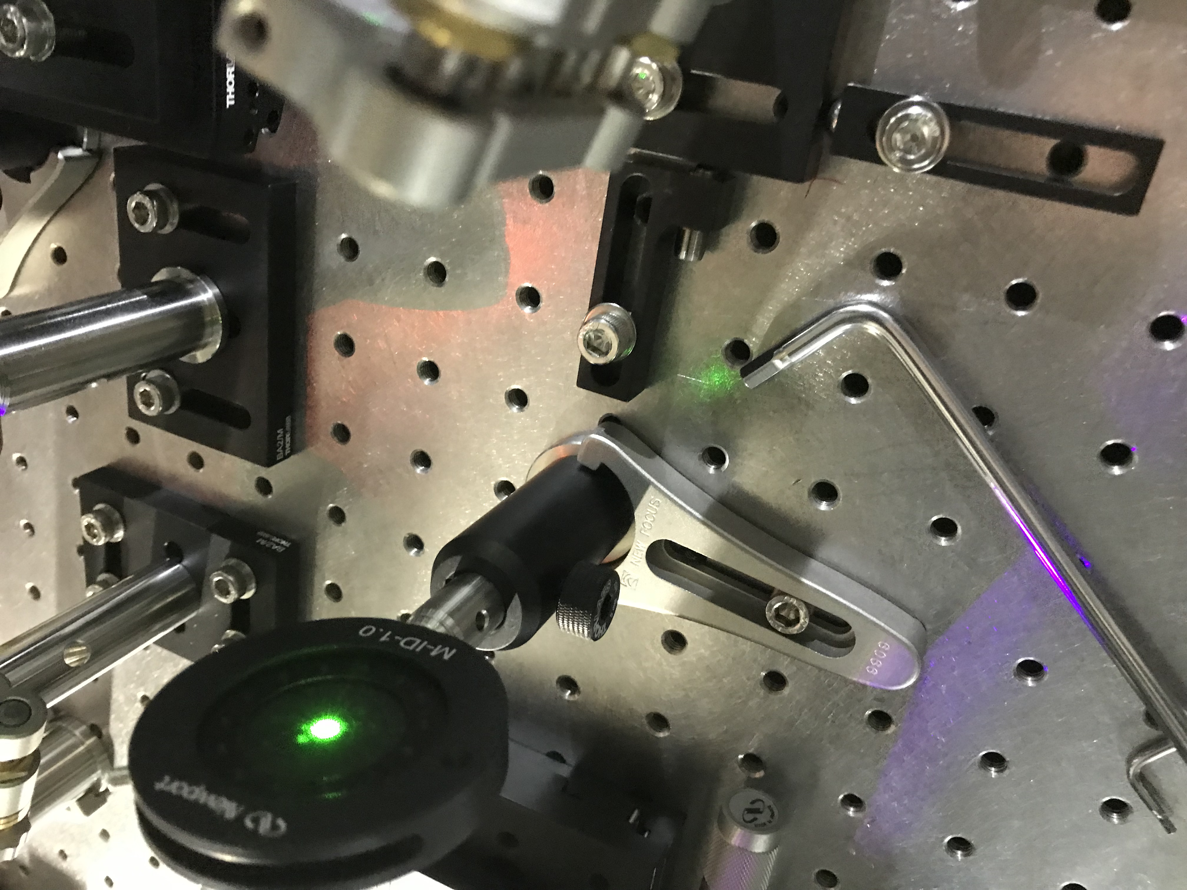
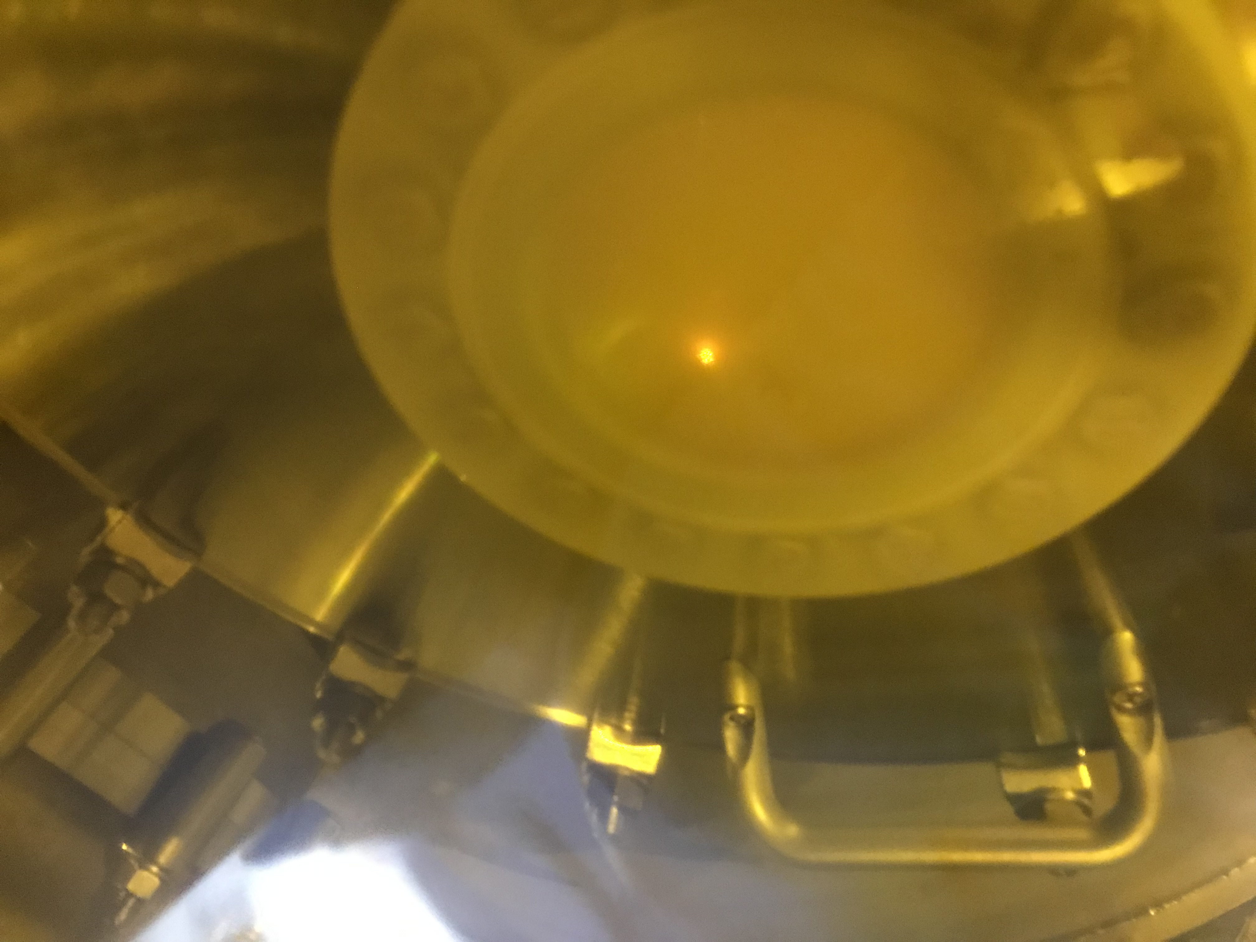
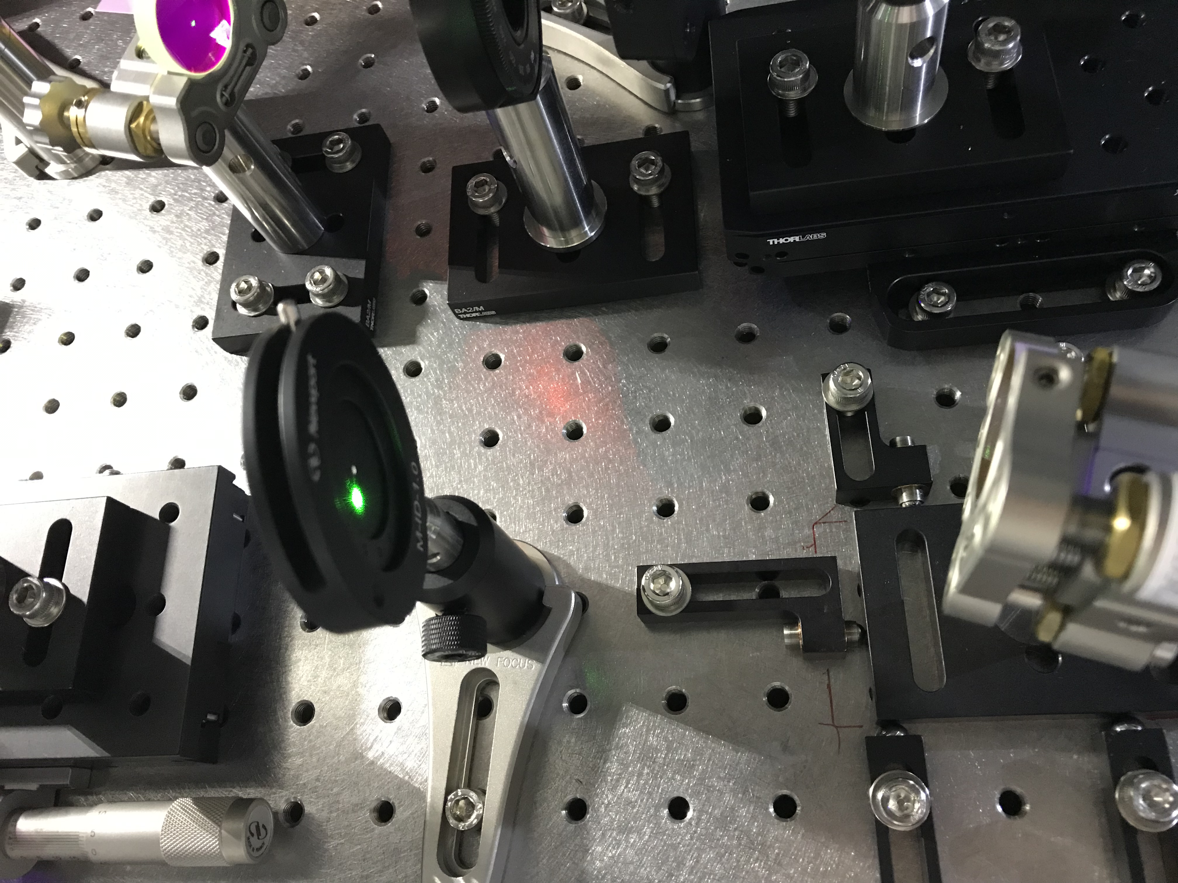
Set two iris diaphragms. One was just before the lens GrL3 (Fig. 3), while the other one is just after the upper mirror of the periscope (Fig. 4). Also I put a cover on the PR2 viewport window and maked the point through which the GreenX went through (Figs. 5 and 6; see for example 17170).
Replacing one mirror
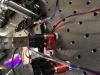
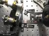
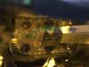
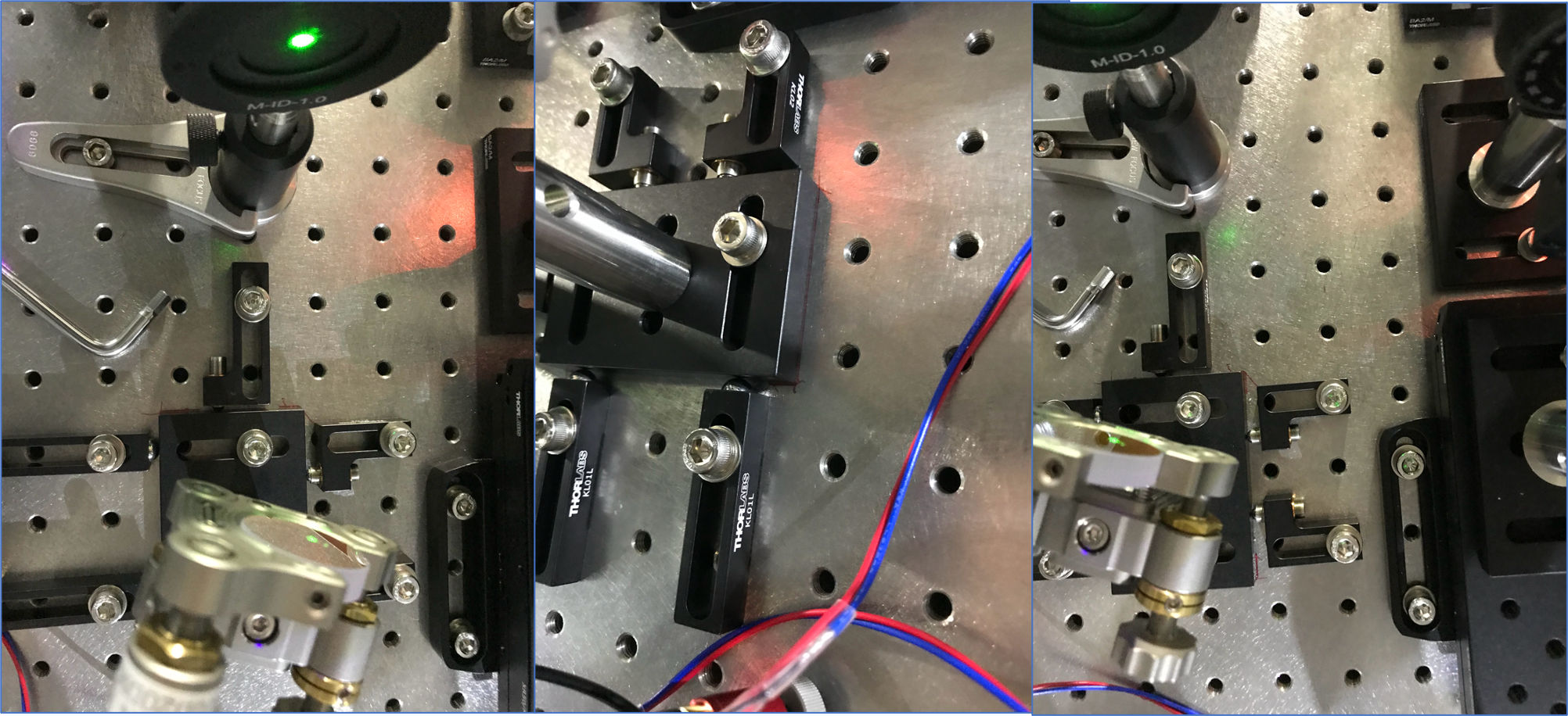
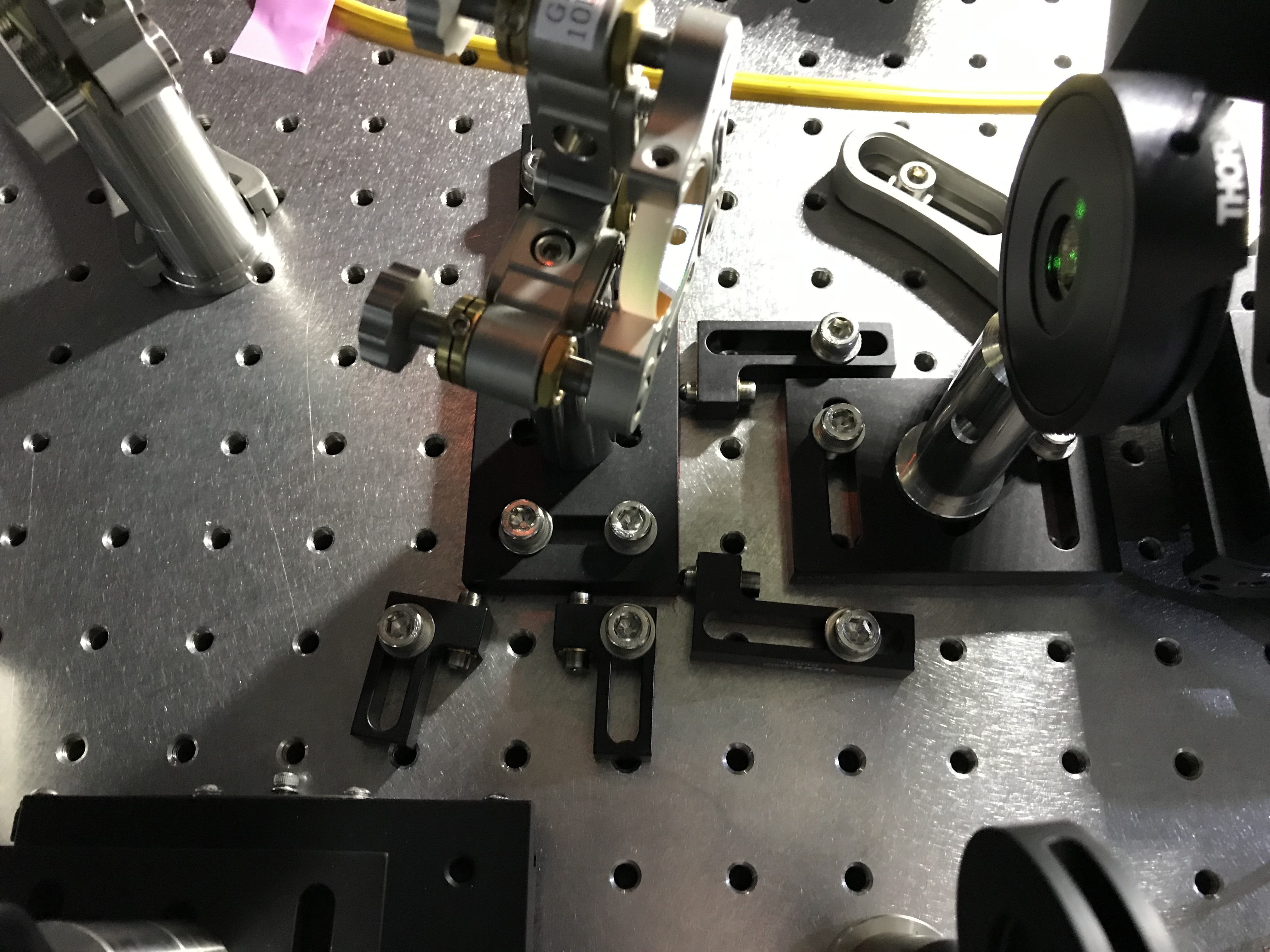
Set several jugs --- positioners and/or guides --- around the target, i.e. the foot plate of the old steering mirror (Fig. 7). As the number of such jigs were limited, I started with setting all of them for GrM3 (the naming convention follows Fig. 6.7 of Yokogawa M-thesis, but this mirror would be assigned to "STM2" in the DGS, later, maybe).
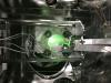
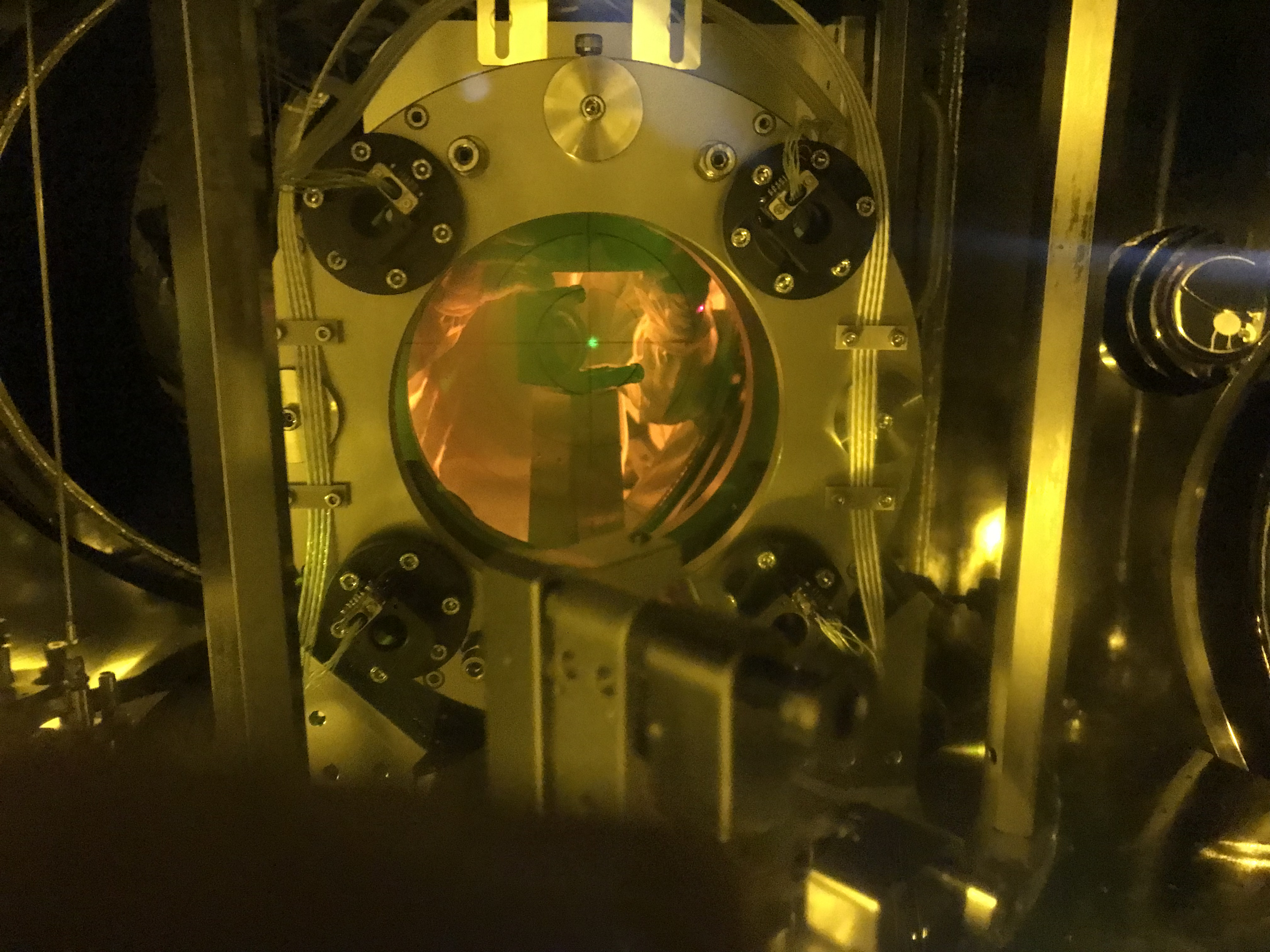
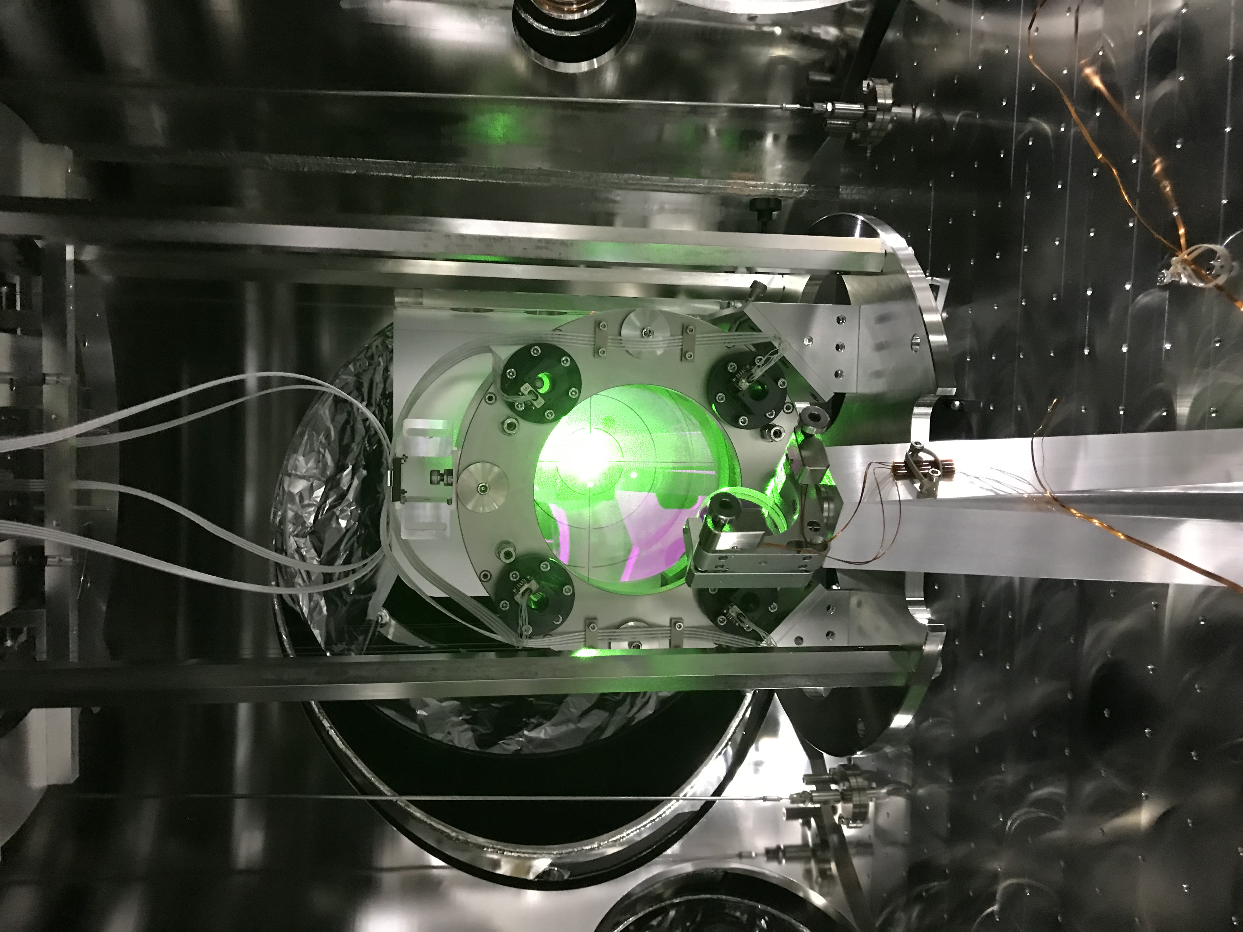
First, I pushed the target back in (about, but as precise as possible) 9 mm (Fig. 8). In this situation, the beam spot was horizontally shifted (see Fig. 9). Then, replaced the mirror mount with the new one, and tweaked only the new mirror's pico motors with my hand referring to the two iris diaphragms and the cross mark on the viewport cover. In the previous discussion, I did not expect the "new nice optical axis" would be achieved only with tweaking the replaced mirror; our principle to the alignment discussed there was using not only the forward optical path vs the iris diaphragms, but also backward ones from ITMX, as we did not expect the iris diaphragms within the relatively short optical path on the POP table would not be sufficient to recover the 3km alignment. But, this time, the real world was not more severe than our imagination; a rare case! Immediately after detaching the cover, I saw a relfection beam from ITMX was reacing the GrRFPD. I even saw the GreenX beam spot with the TMSX GigE camera, and also saw that the TMSX GrDCPD showed some responses. These meant the optical path was mostly recovered already. After checking the green beam is hitting around the center of PR2 (Fig.10; slightly shifted to +Y side... but this might be from the "first"; see the past klog pst anywhere), I asked Miyo-kun to sweep the PR3. According to him, the PR3 only needed to be displaced about only a few x 10 urad to find the best alignment. Ok.
Replacing another mirror
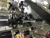
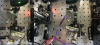
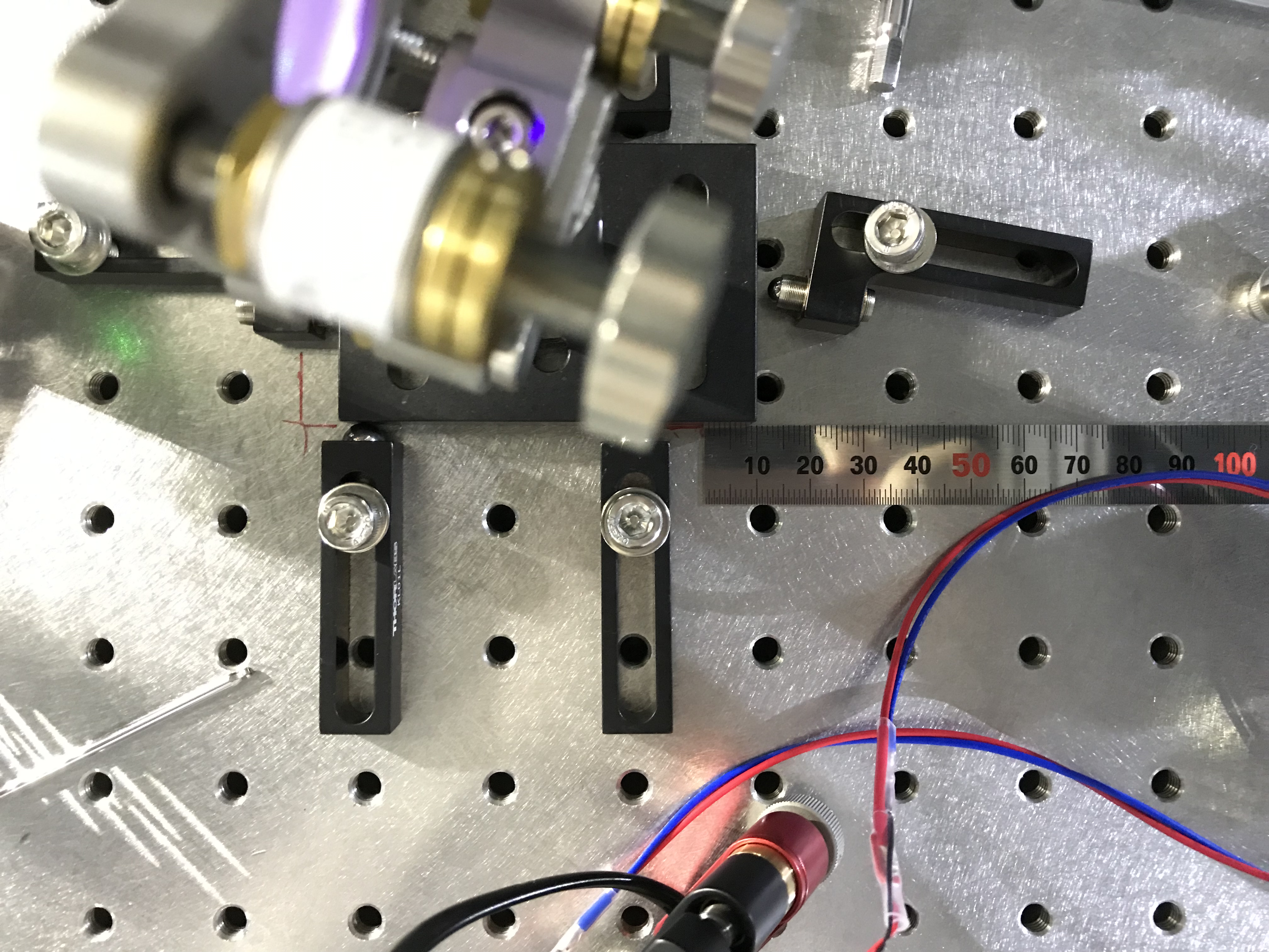
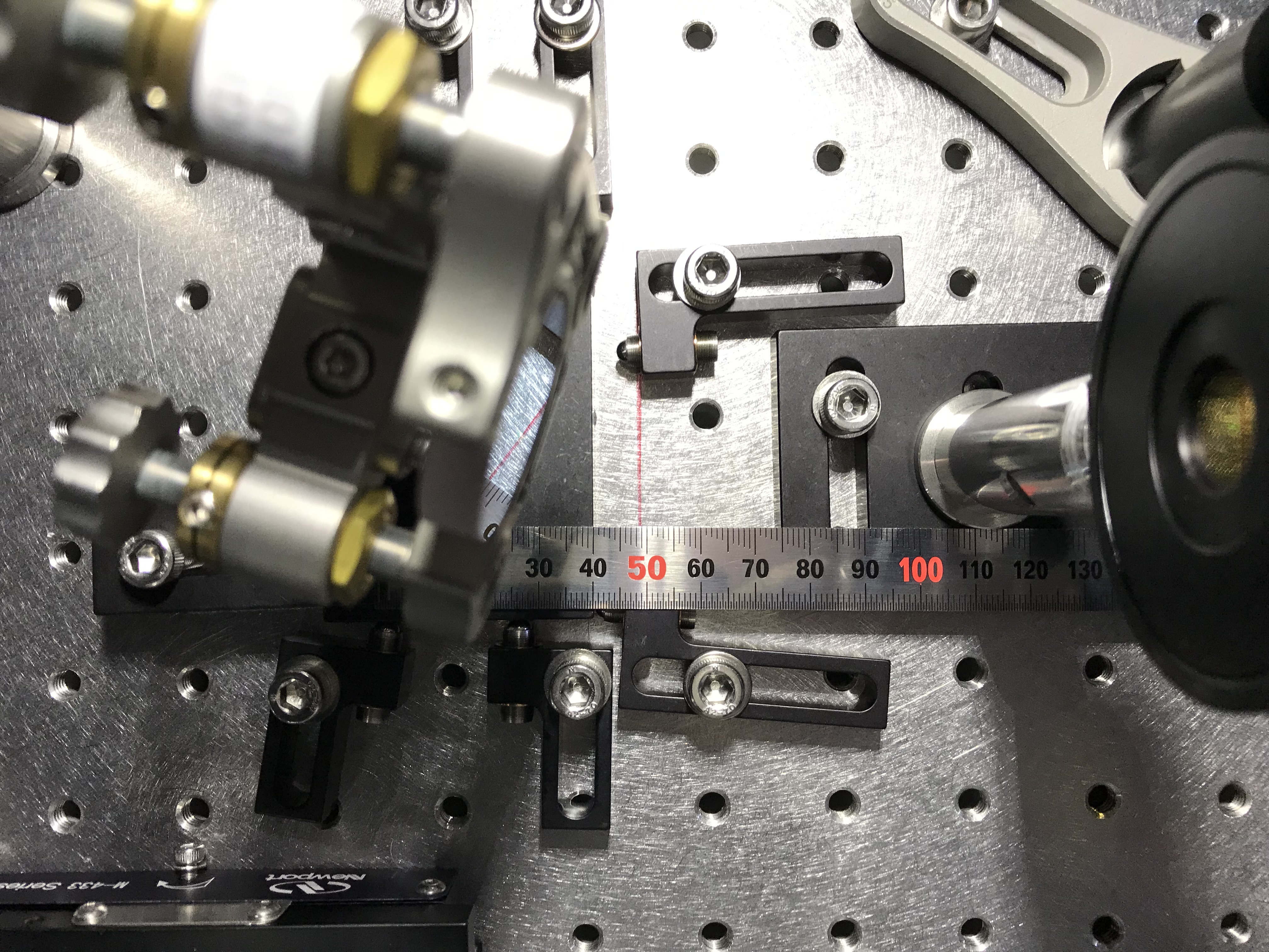
In the same manner, I setup the jigs around the next target (Figs. 11 and 12; there seems two positioners in the direction to push, but only one side of them was used, and the other one was just for a support to hold it not to start rotation, so I did not "actuate" it during this procedure), i.e. the foot plate of the other steering mirror (GrM2 in the Yokogawa thesis, and will be assigned to "STM1" in our DGS). The positions of the two iris diaphragms were unchanged and left. The viewport cover was once detached, but I reset it here. In the same manner, pushed the target back in 9 mm. This time the surroundings were crowded, so I used satellite-iphone-photo-taking way ... checked the move amount by photos taken from the sky, and finally did it (Fig. 13).
Similarly with the first time, with tweaking only this mirror's pico motors with my hand, the beam passed through the iris apertures and hit the mark on the viewport cover. Detaching the viewport cover, I could immediately find the reflection from ITMX and transmission through ETMX. After checking the centering on PR2 (Figs. 14 and 15), I asked Miyo-kun to sweep PR3 for the fine tuning.
The resultant situation is shown in Fig. 1.
Guess
It was nice that I could finish this without any severe iterative alignment work. Looking back what were nice would be valuable.
- Wearing a laser safety goggle, the green spot seemed like a tiny spot to my eye balls. This was very helpful to align the iris apertures to the beam line and could be one of the causes to achieve this precise alignment only onn the POP table. Maybe I could not do this precise tuning for the IR beam... A laser viewer type that nicely fits to may face/eyes would be required for that case.
- The viewport cover marking would be one of the most important factors...
- Pushing gently with the positioner would be one of the causes of this success.

