Reports 1-1 of 1 Clear search Modify search
VIS (SRM)
ryutaro.takahashi - 9:32 Saturday 14 March 2026 (36579) Print this report
Assembly of new mirror

(Work on 13th)

[Hirata, Washimi, Takahashi]

This is a rapid report. Details will be reported later. We started assembling the new mirror. We found that the new mirror (85%) is thinner than the old mirror (70%). Measured thickness with vernier calipers was 7.9mm for the new mirror and 9.6mm for the old mirror at the edge marker. The thickness of the shims (#9 in Picture) was 1.5mm. Therefore, the flange (#5 in Picture) couldn't fix the mirror even if the shims were not used.

Images attached to this report
Comments to this report:
naoatsu.hirata - 8:49 Monday 16 March 2026 (36580) Print this report

(Work on 13th, detail report)
[Takahashi.R, Hirata]

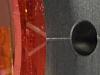
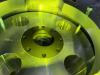
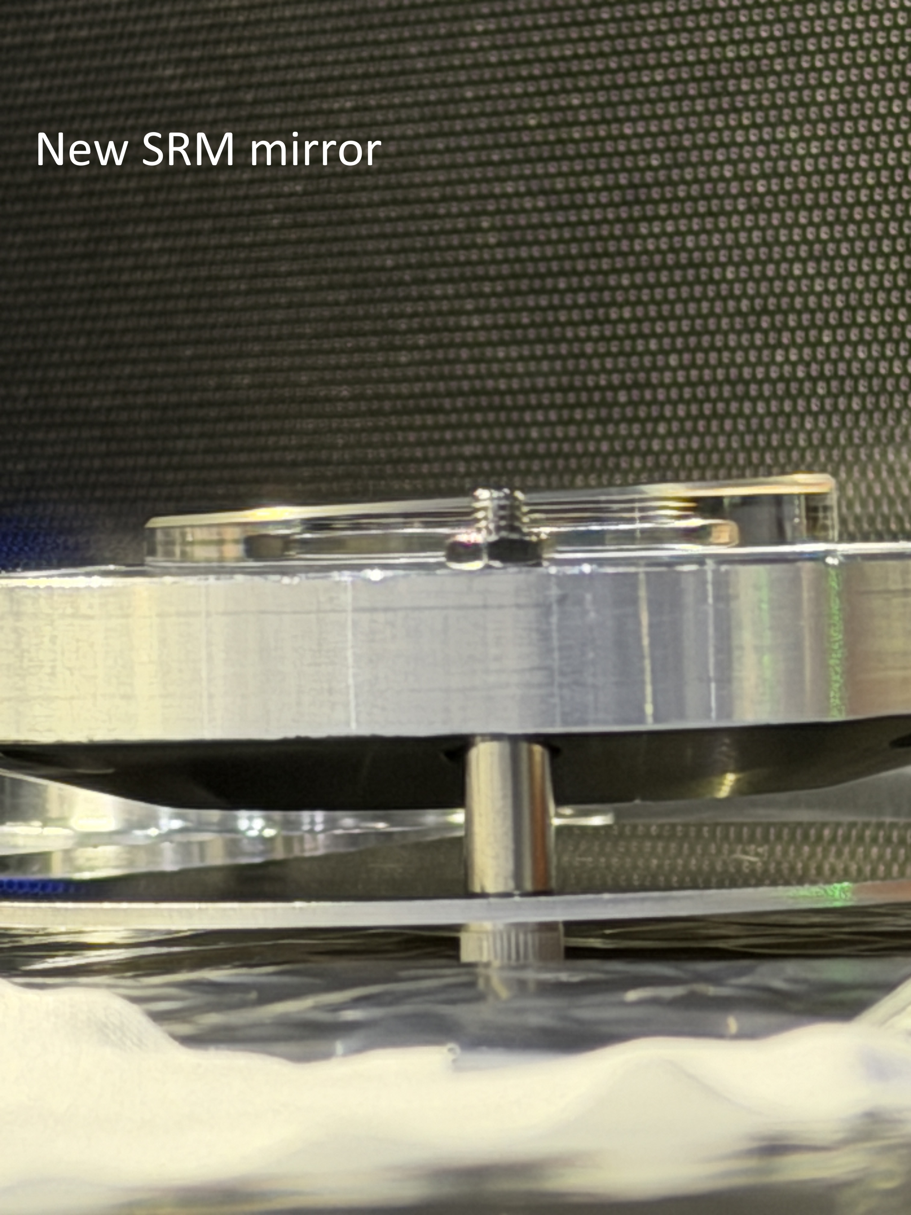
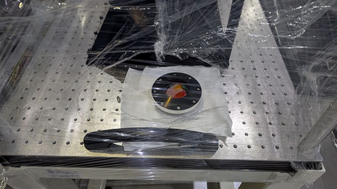
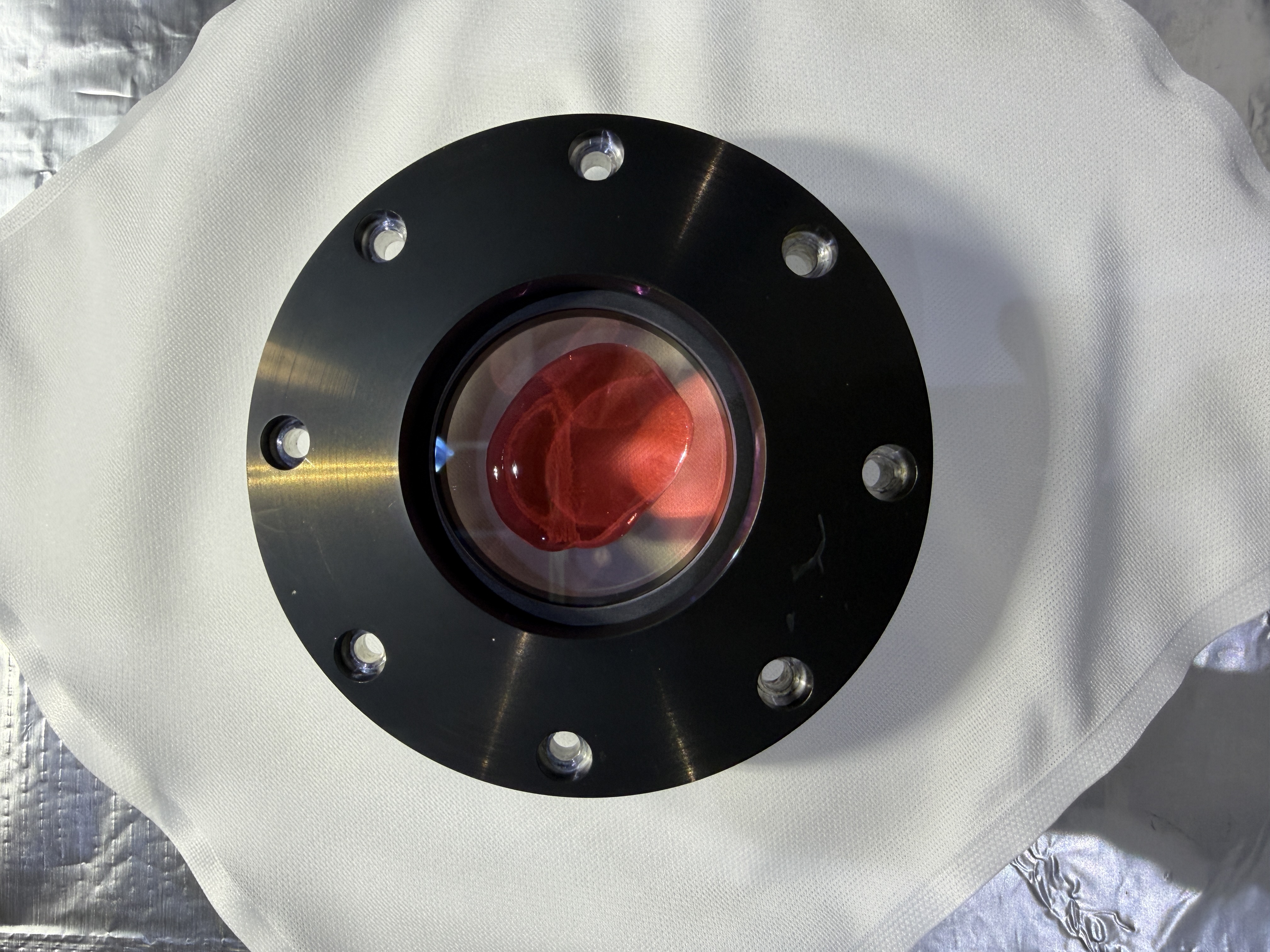
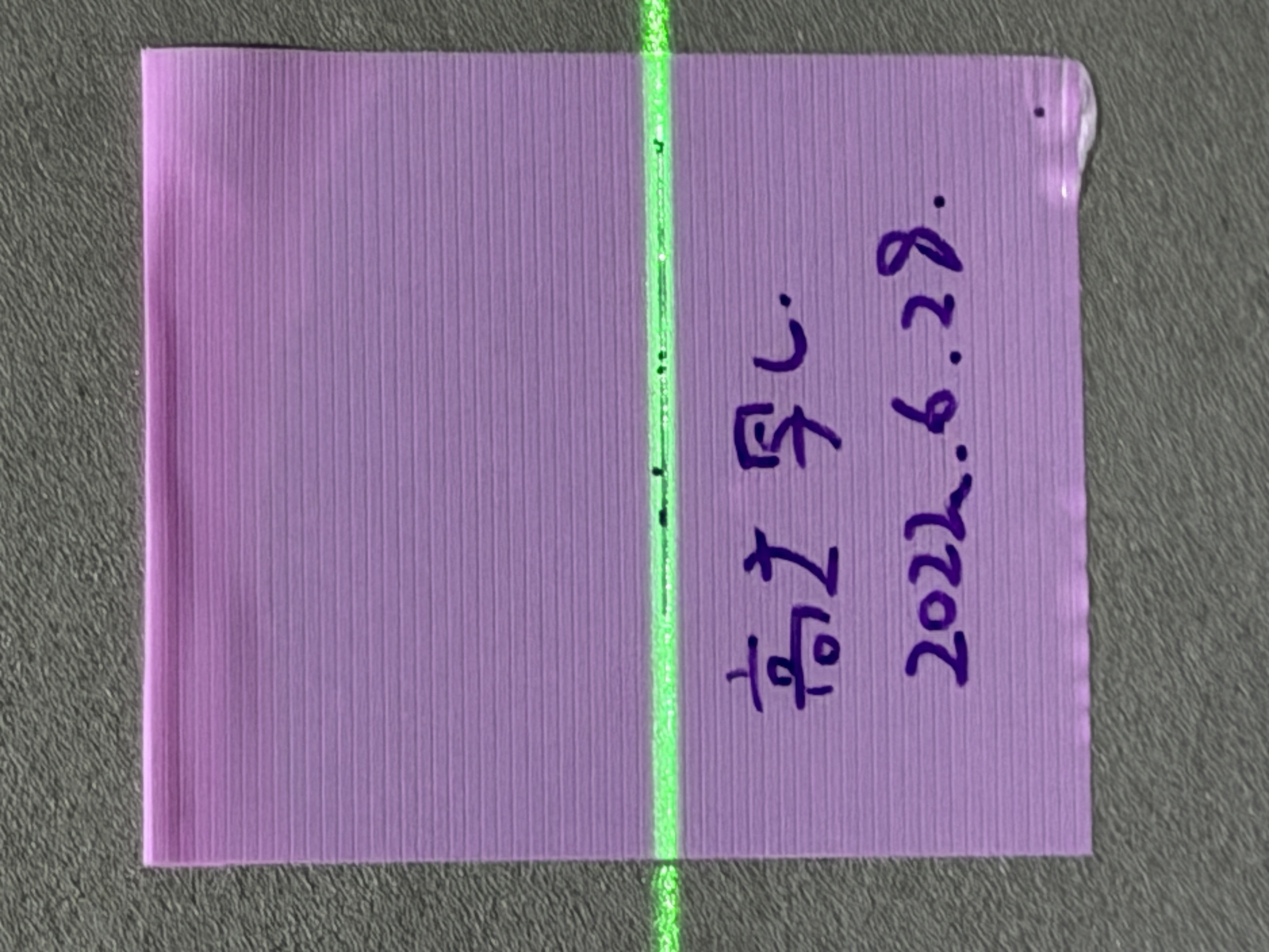
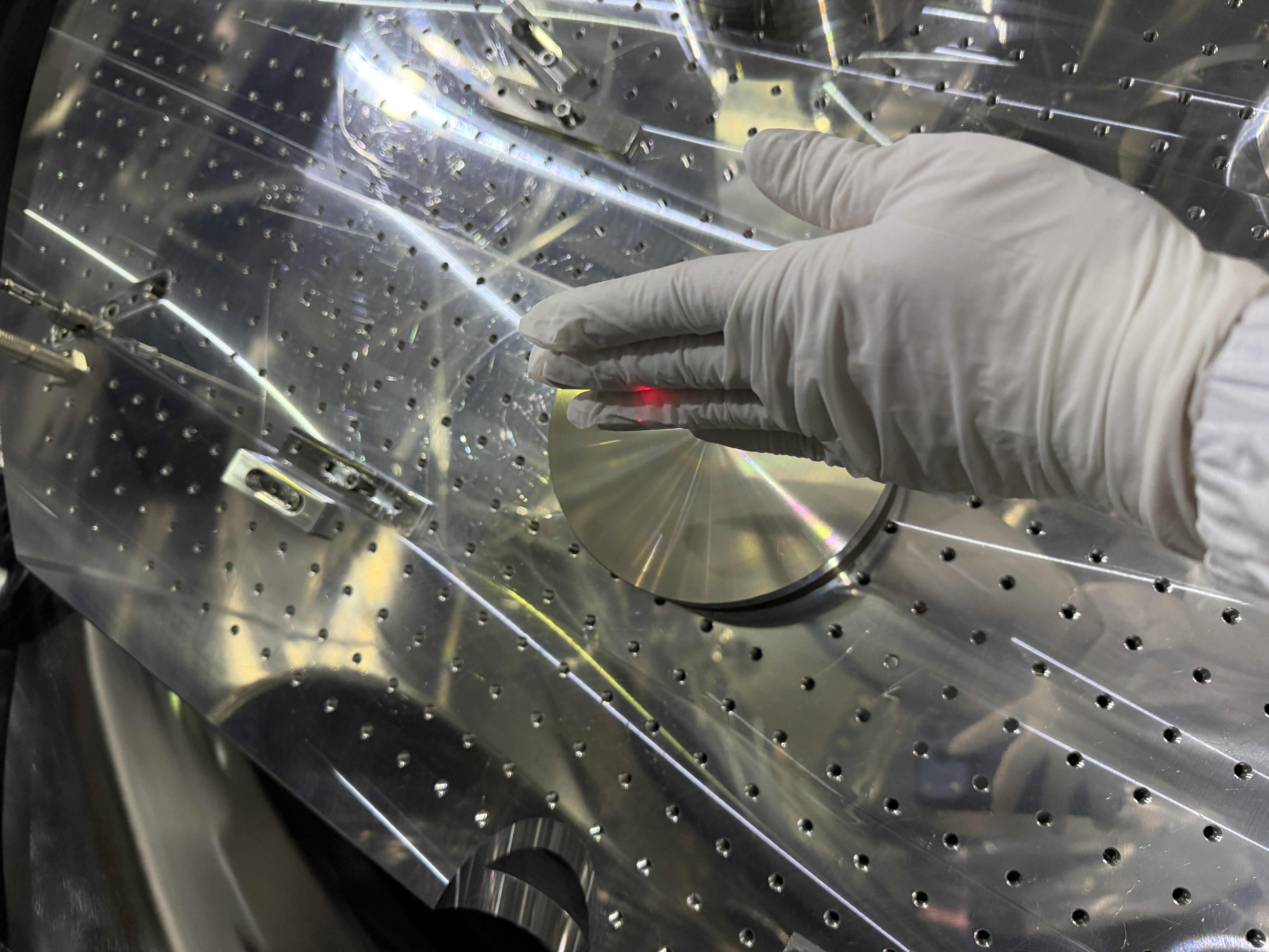
We assembled new 2inch mirror for SRM(pic1), and we reallized the new mirror was thinner than previous one, so we couldn't secure it properly.
At the end, we re-assembled SRM-M mirror again.

0. Preparation
We set two desktop COACH filters on the working desk. 

1. First contact(FC): new SRM mirror
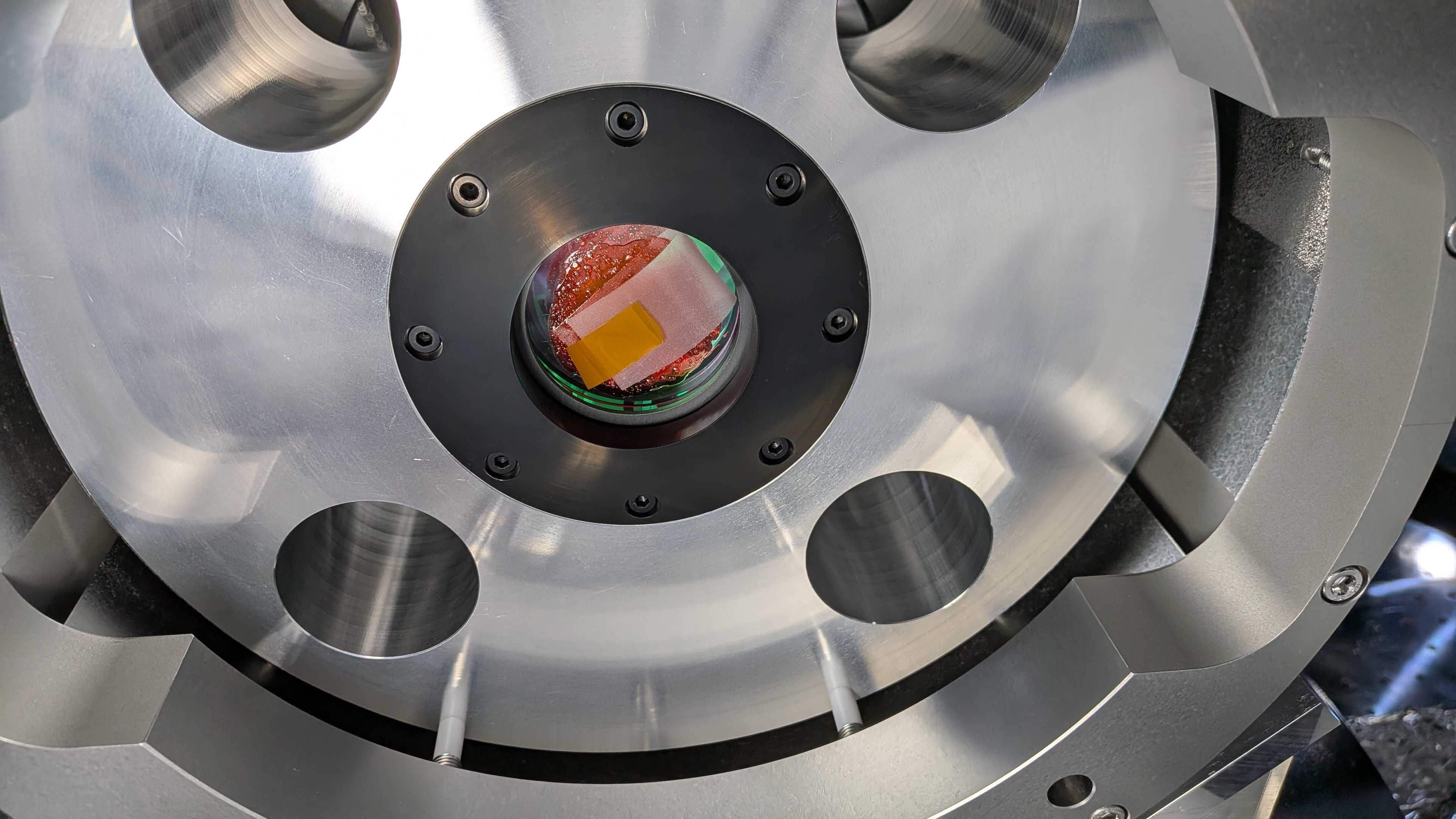
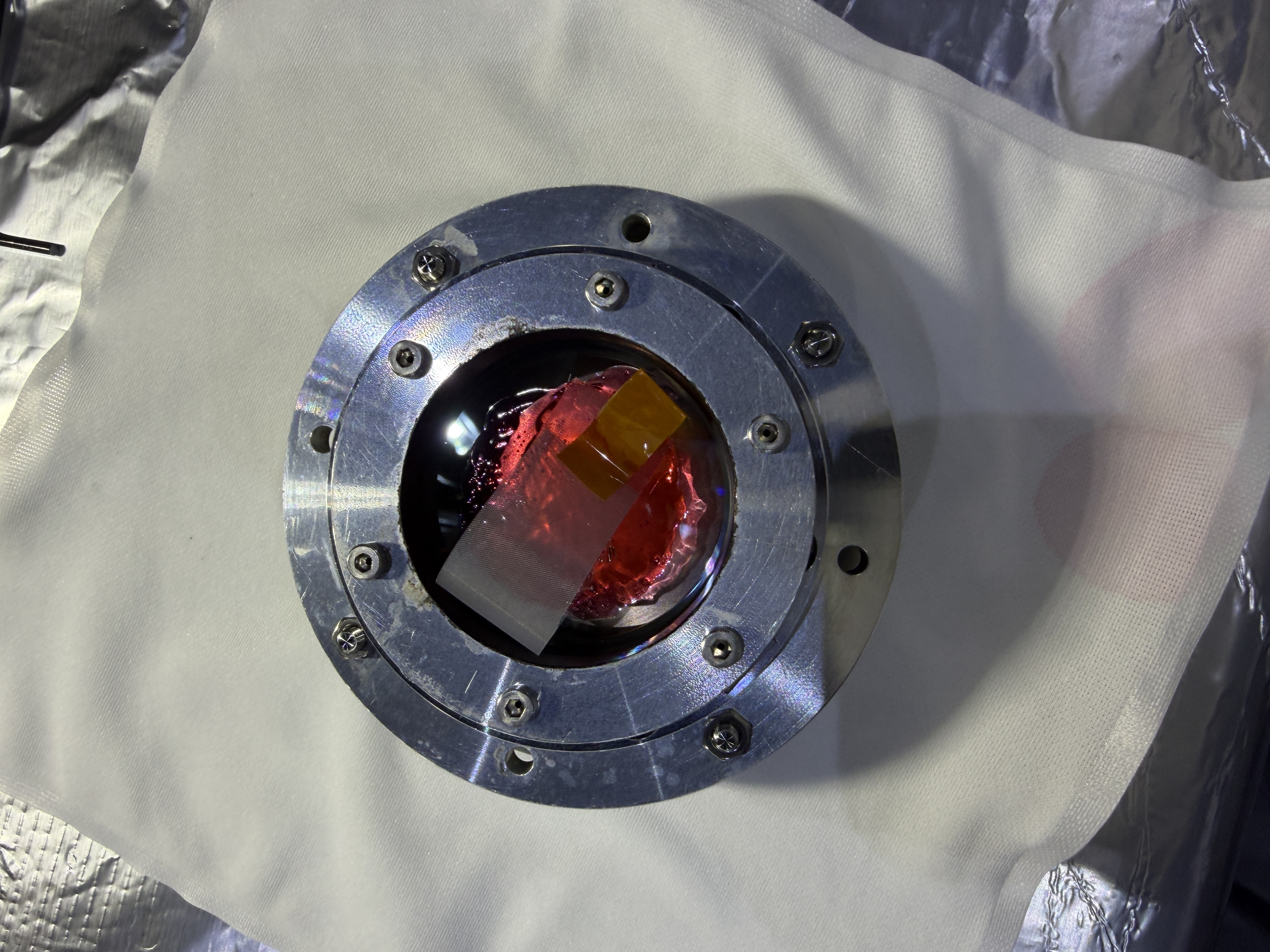
・I put FC on AR and HR side of new SRM mirror.
・First, FC was pour into the stainless bottle.
・5min later, pour FC to the center of mirror. I used brush to enlarge the FC area.(The tip of brush can touch FC only.)
・Few minutes later, I put tag on the surface of FC. The direction of the tag should not cover the triangle mark on the side of mirror.
・15min later, I changed surface and put FC again.

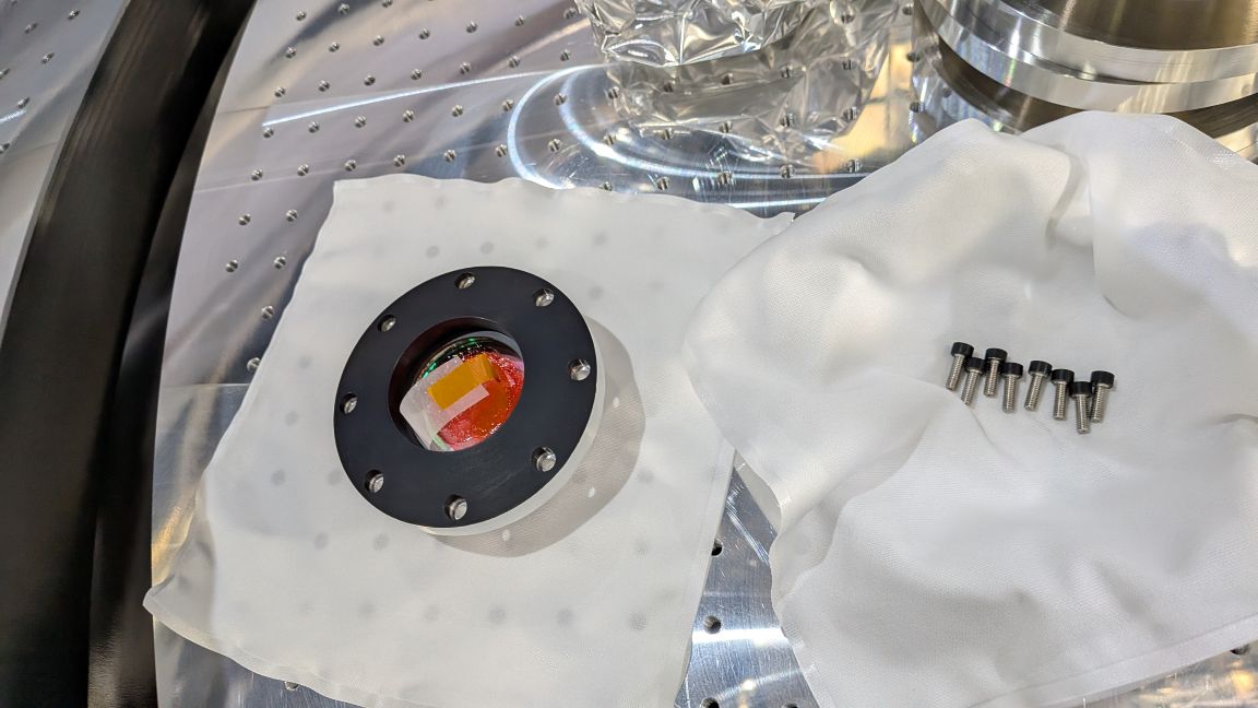
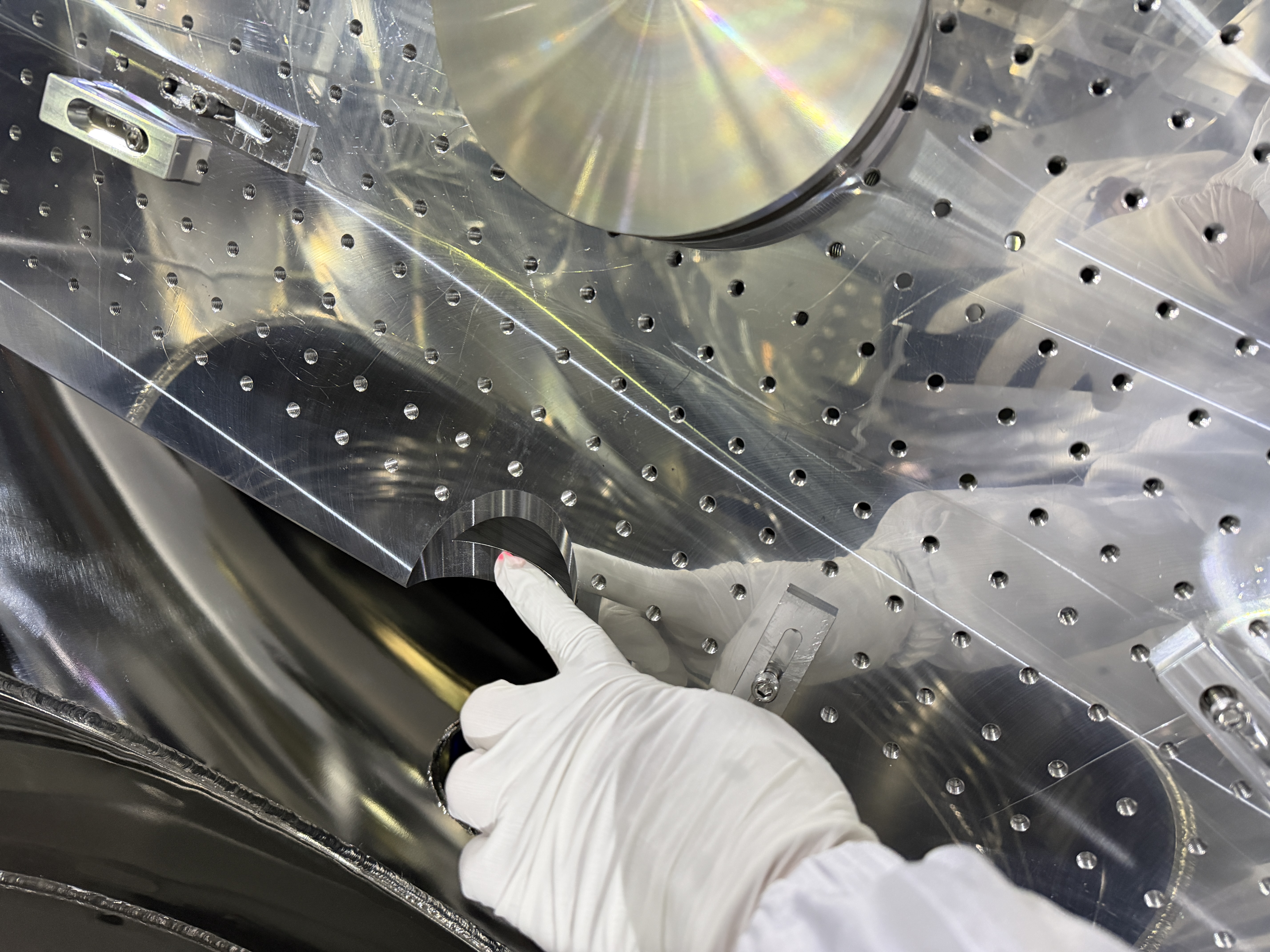
2. Disassemble SRM-M
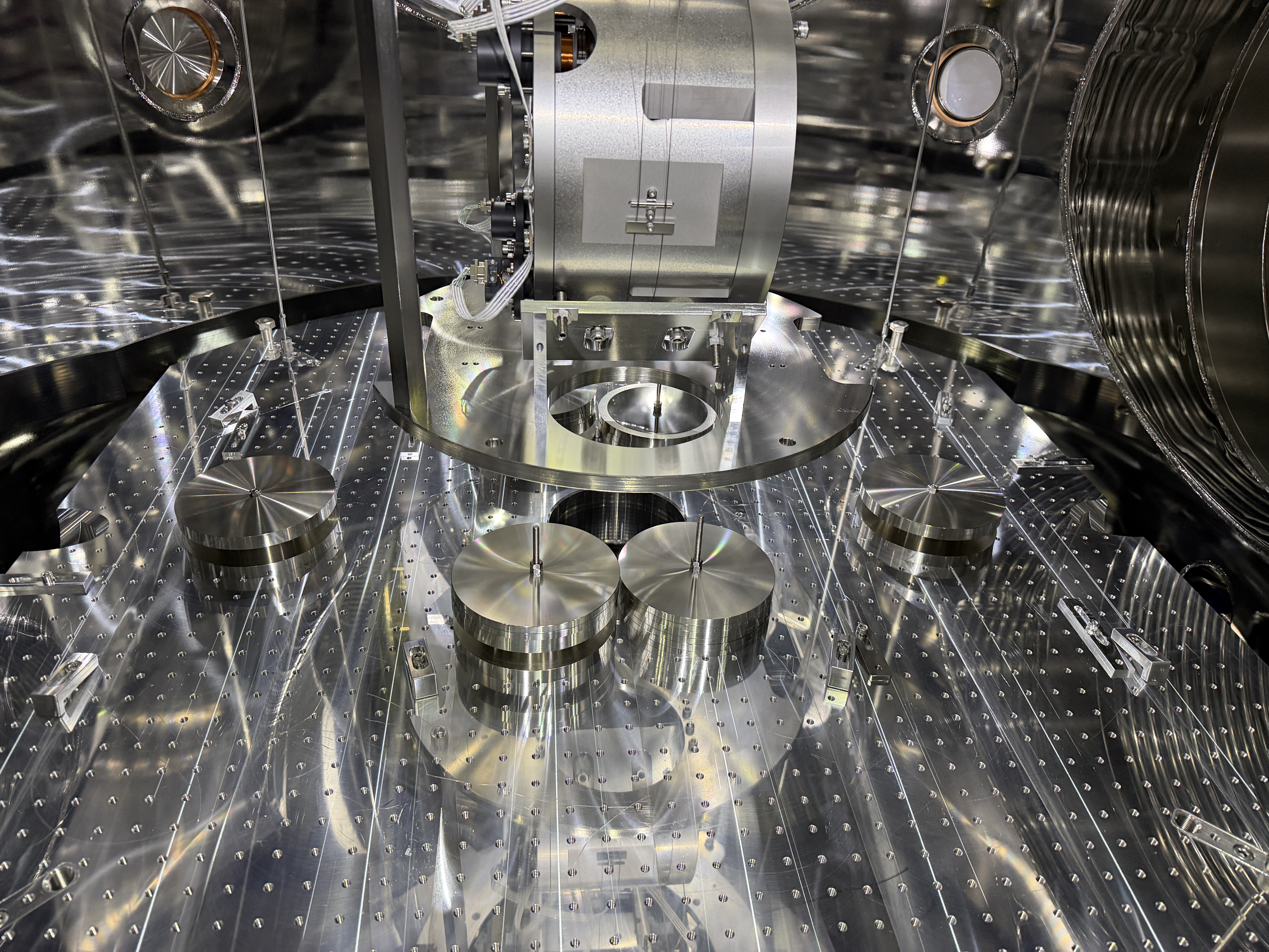
I disassembled SRM-M mirror assy. It stored inside the decicator at the OMC area.
The shim plates for the six M3 screw were kept separate so they wouldn’t get mixed up.

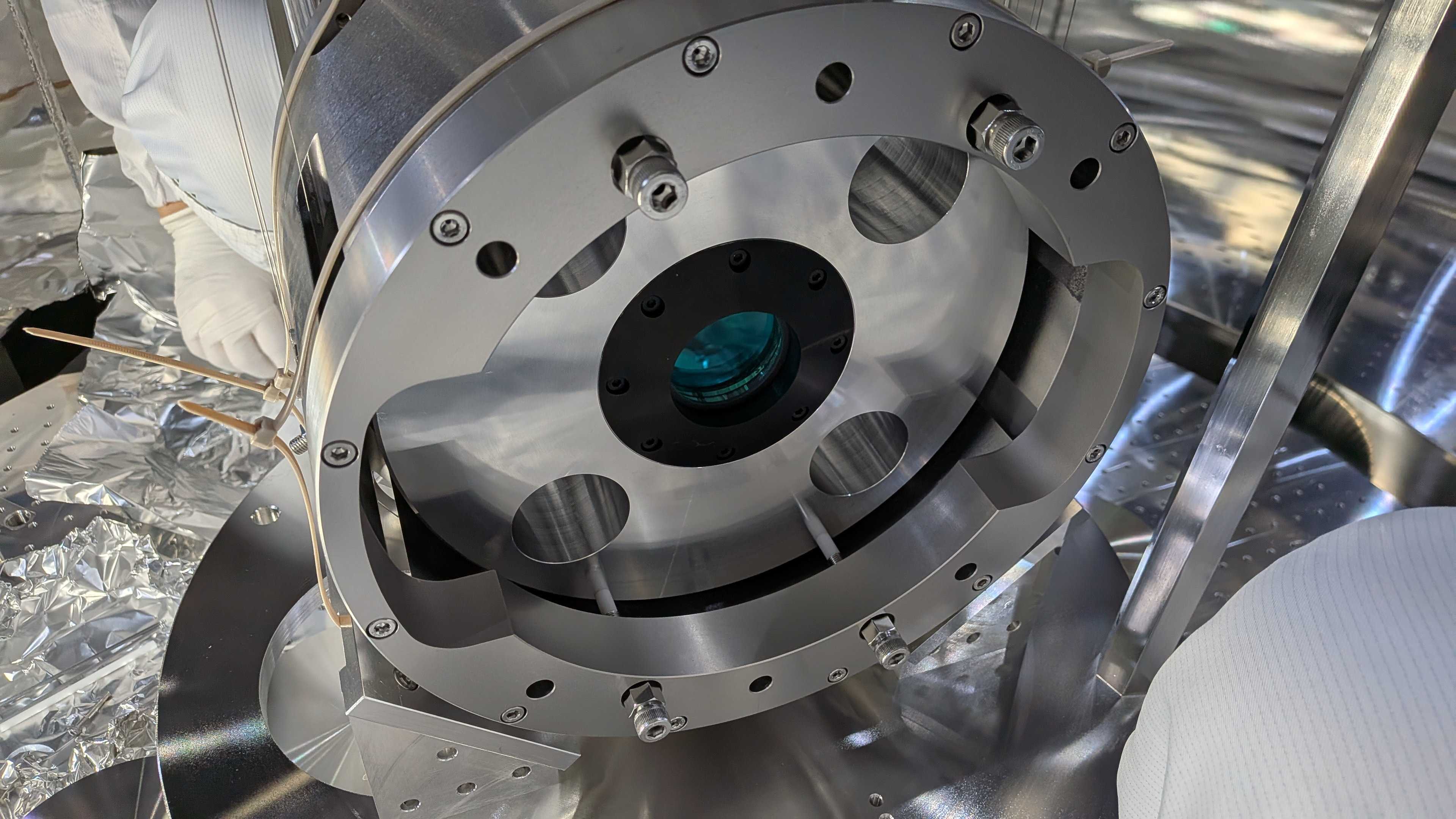
3. Assemble New SRM mirror
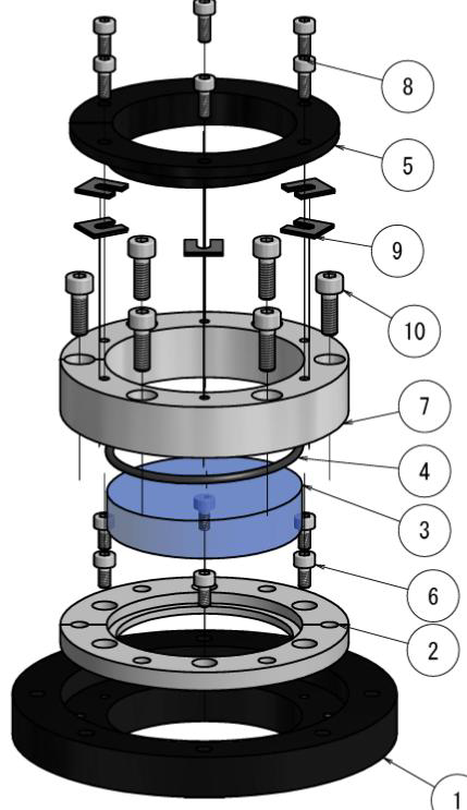
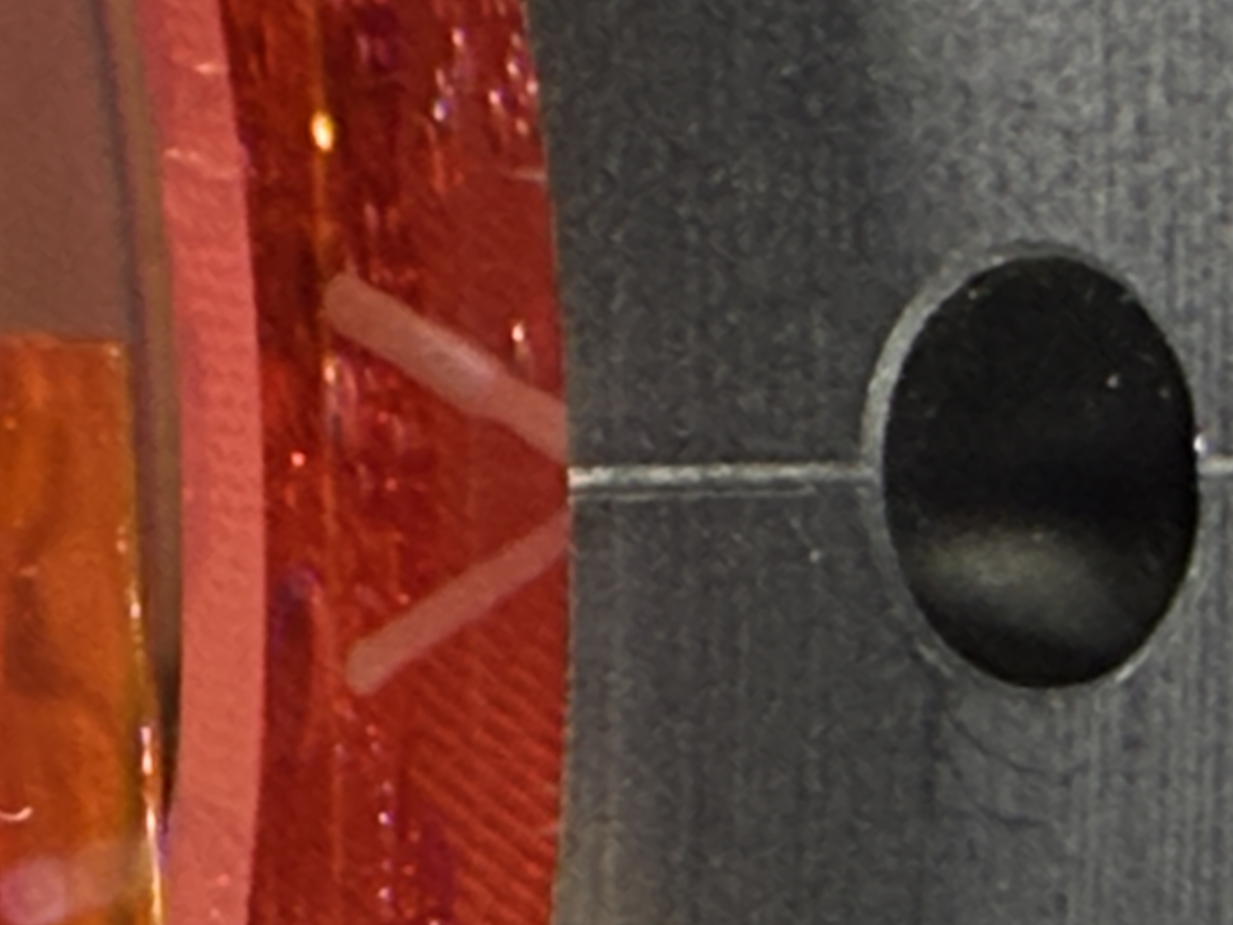
・Align triangle mark which is on the side of mirror with scruch line of the black parts(parts#2).
・Assembled parts#7 and tightened M4 screws with 1.5Nm.
・Put O-ring on the mirror surface.
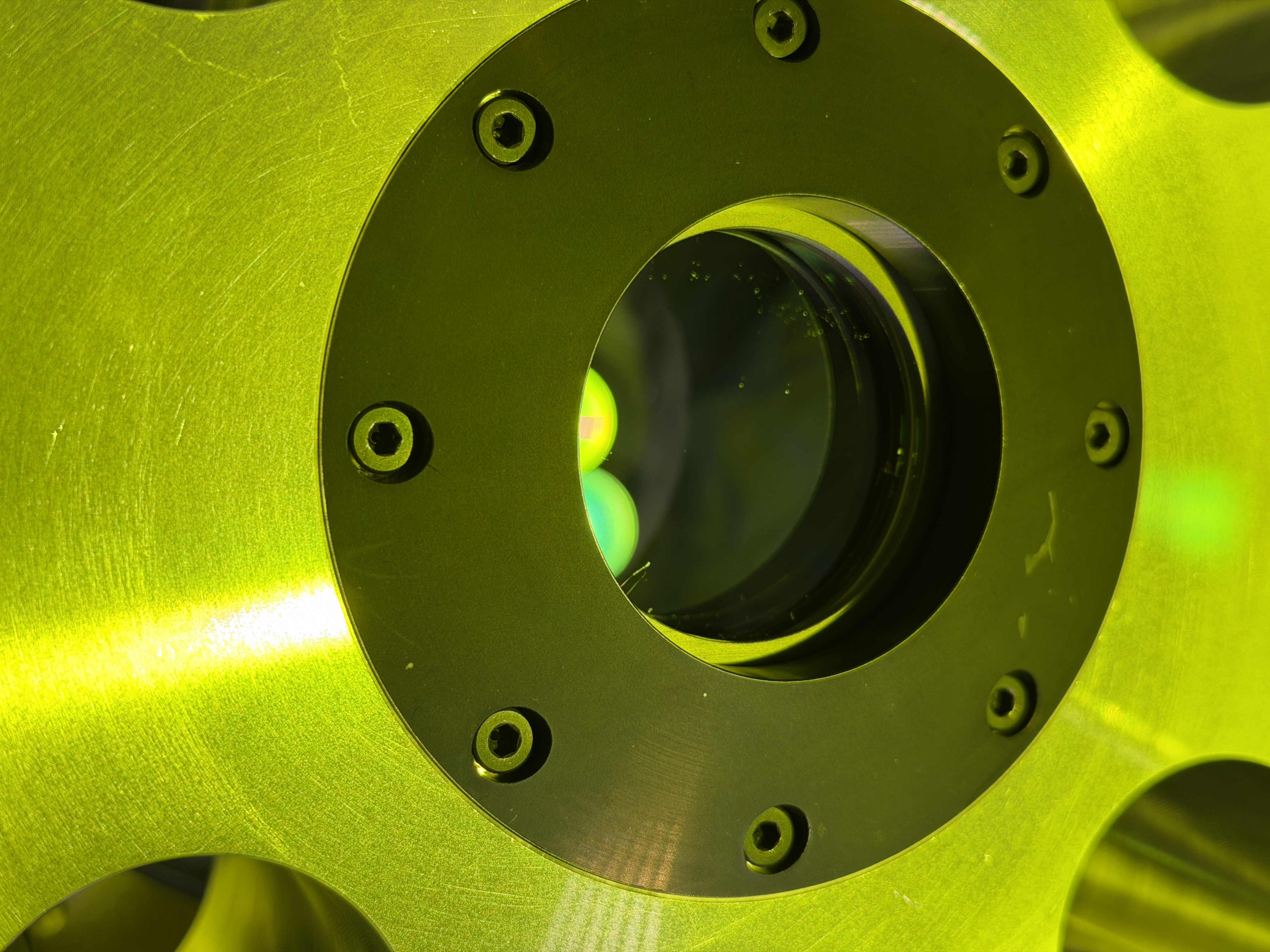
・Assembled parts#5, #9(shim plates). And realized the gap between parts#5 and parts#7 seems almost zero.
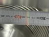
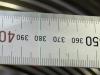
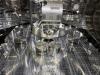
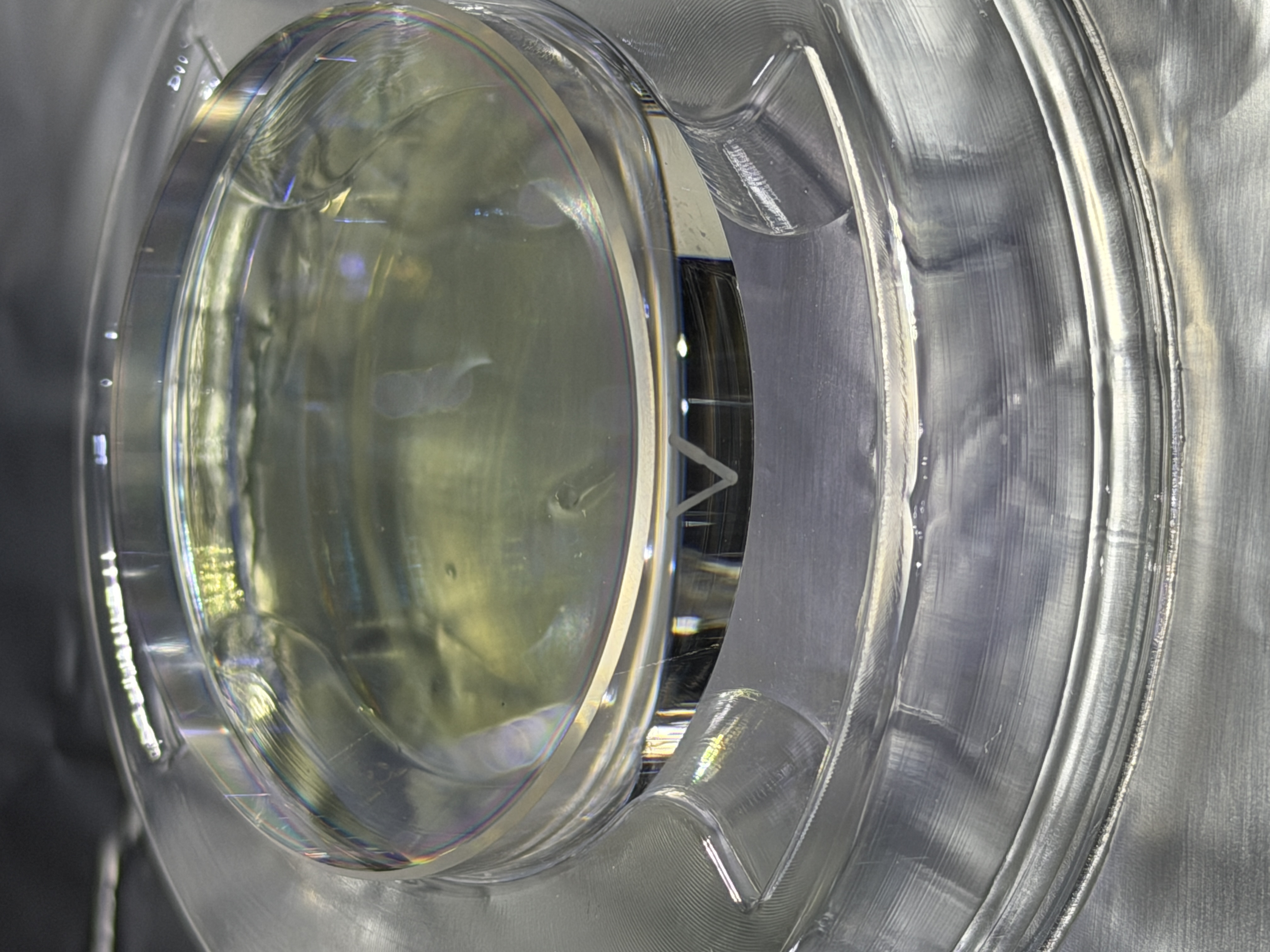
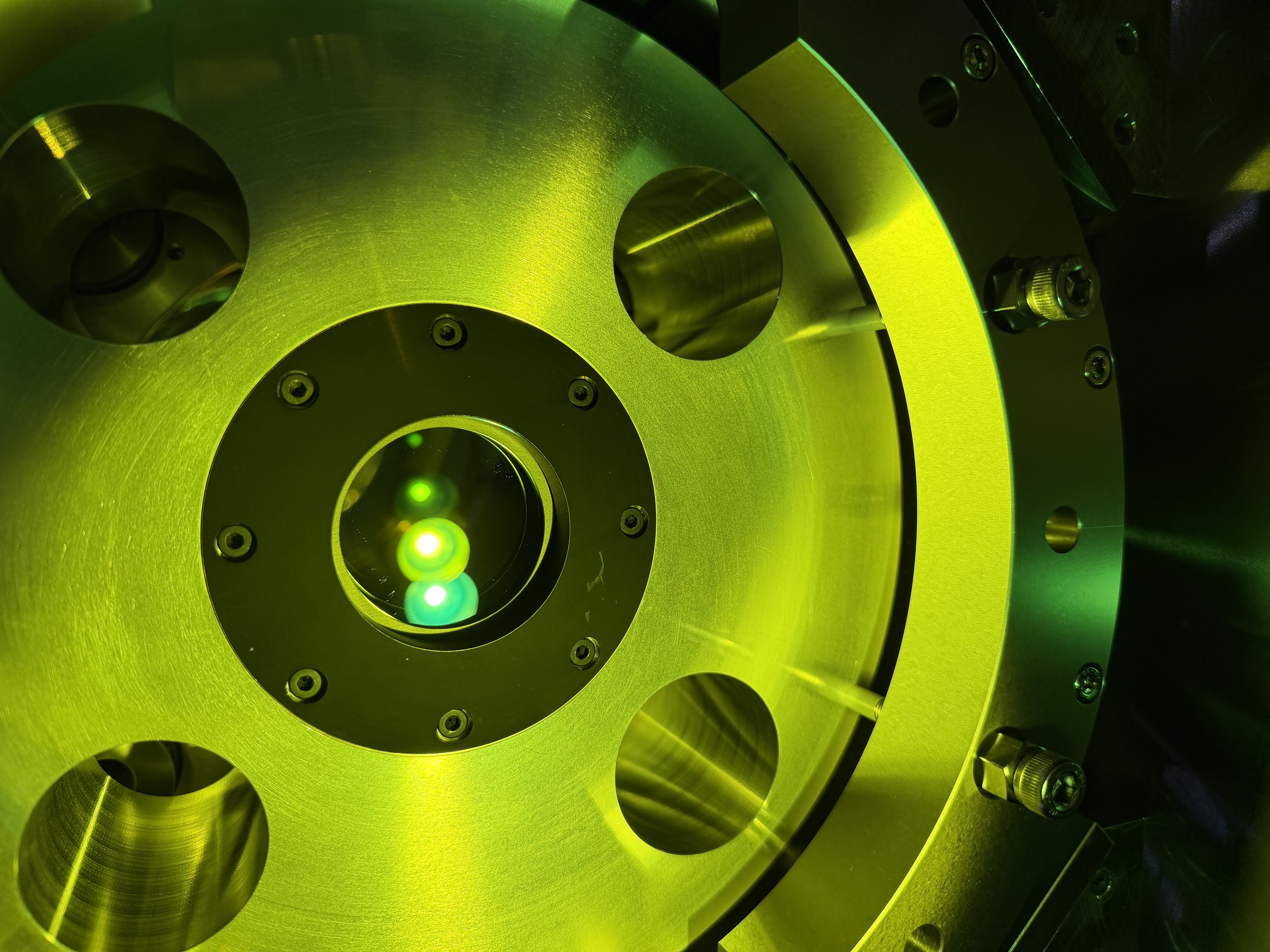
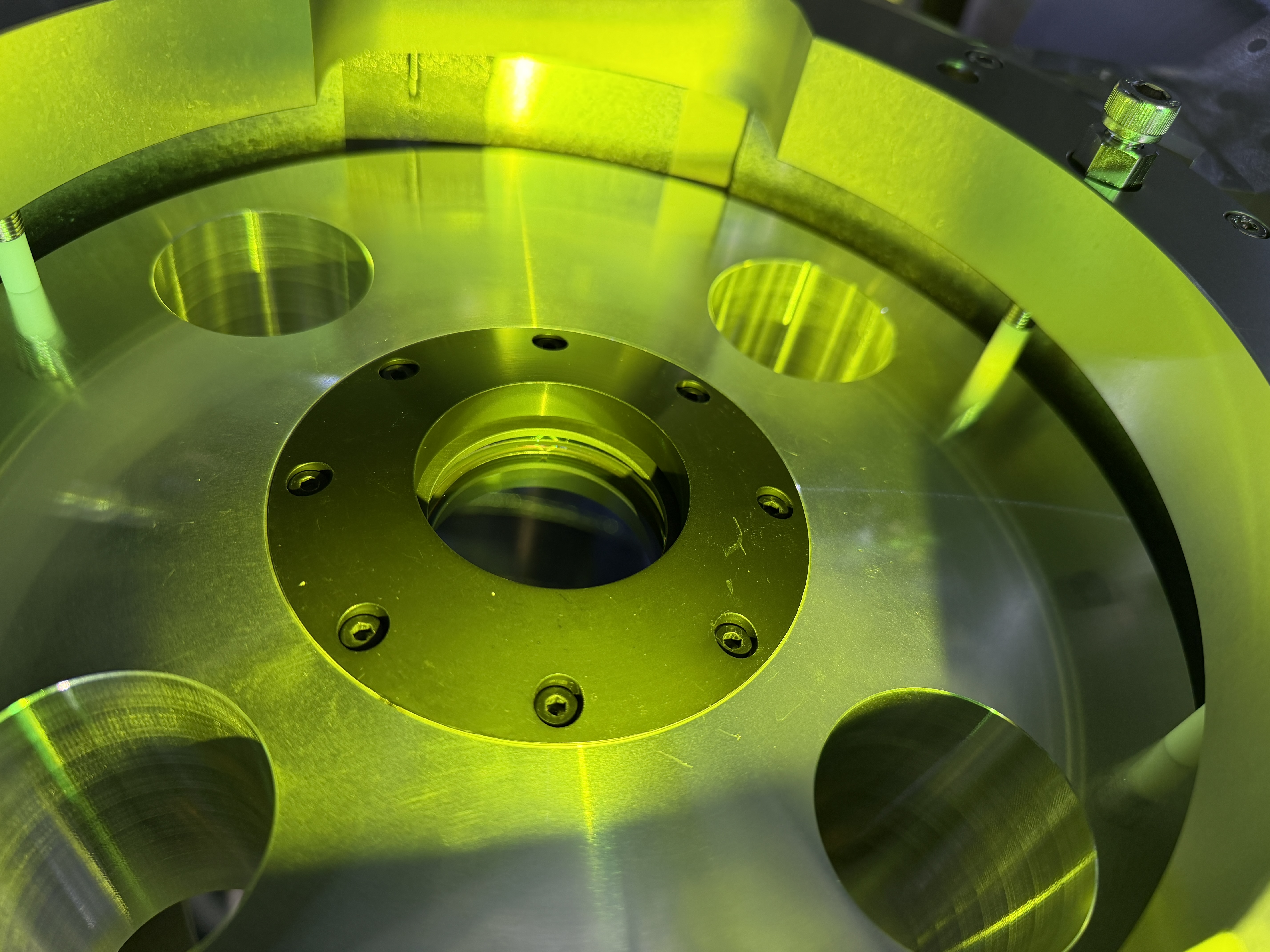
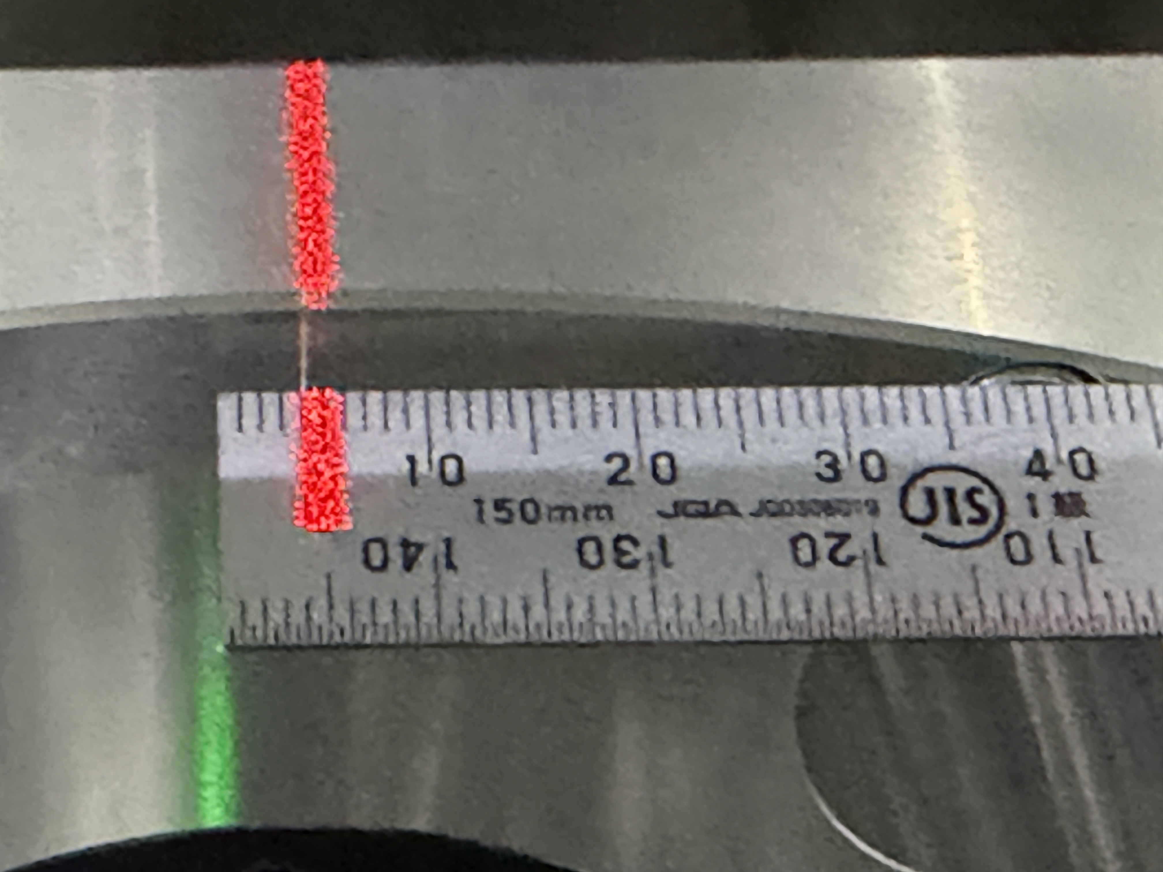
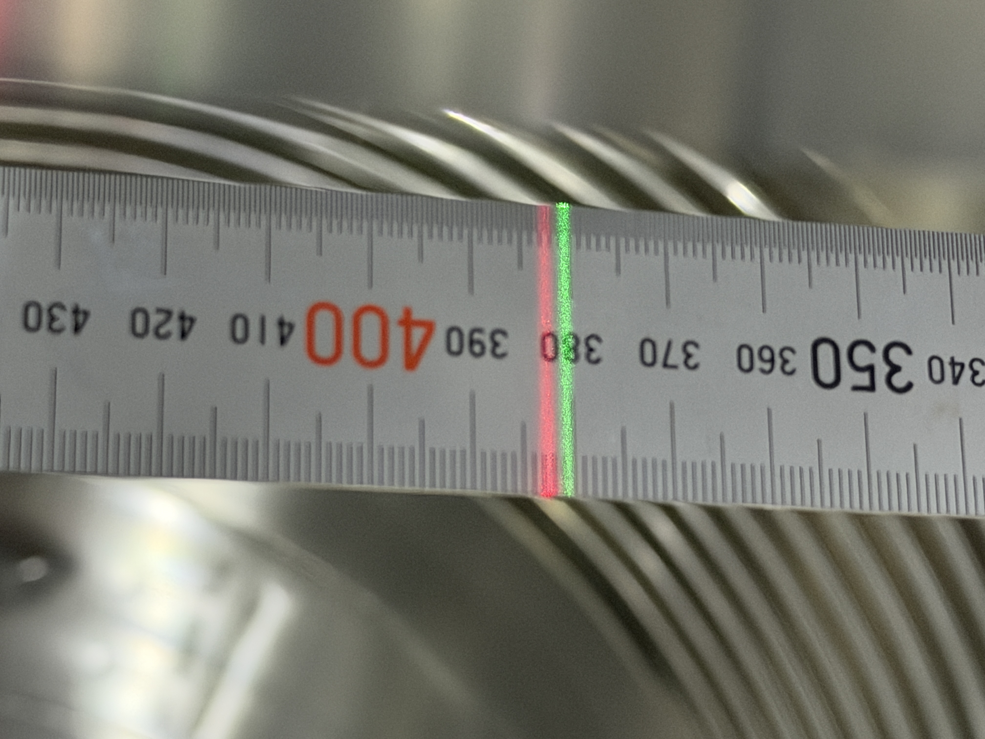
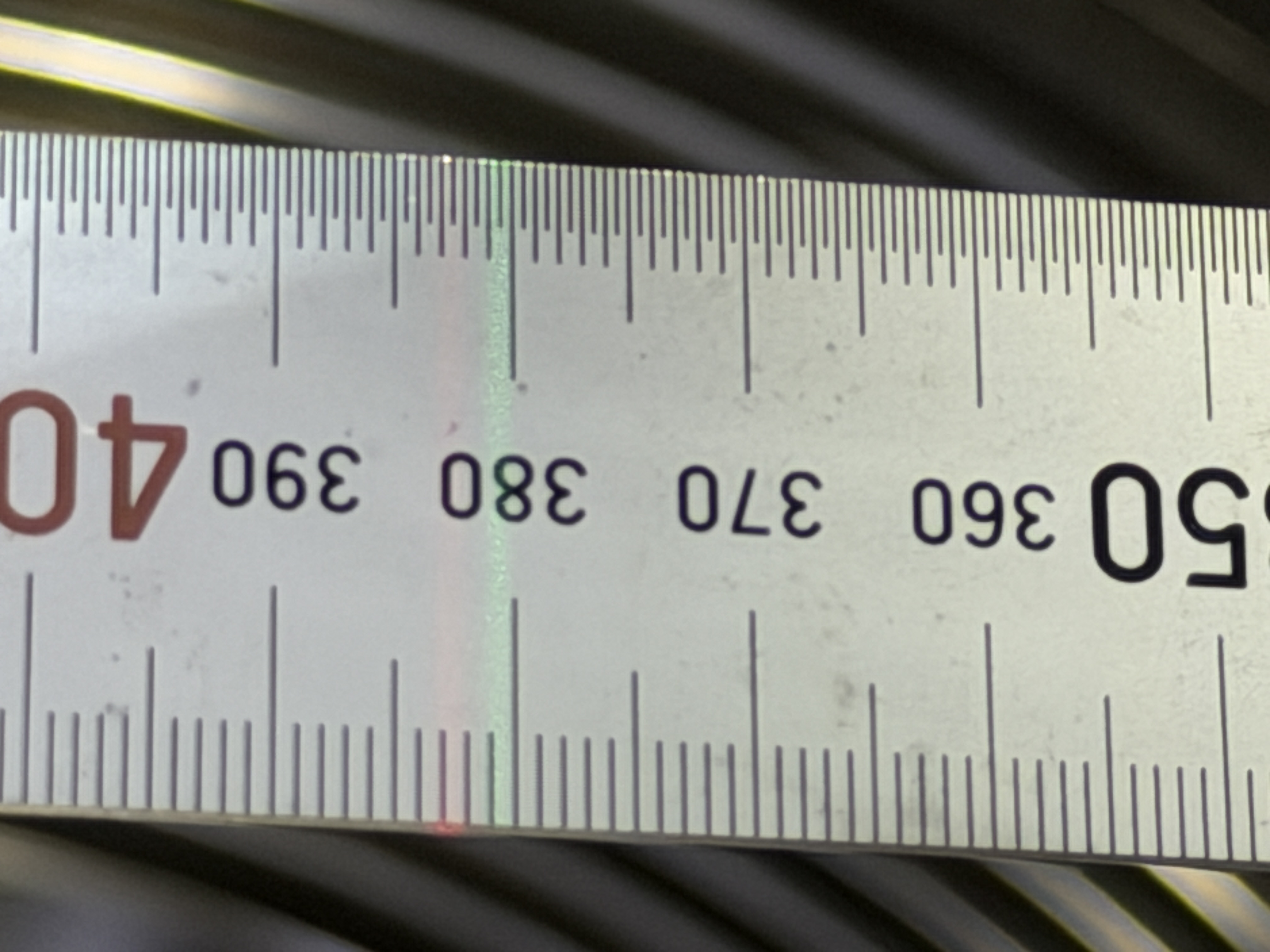
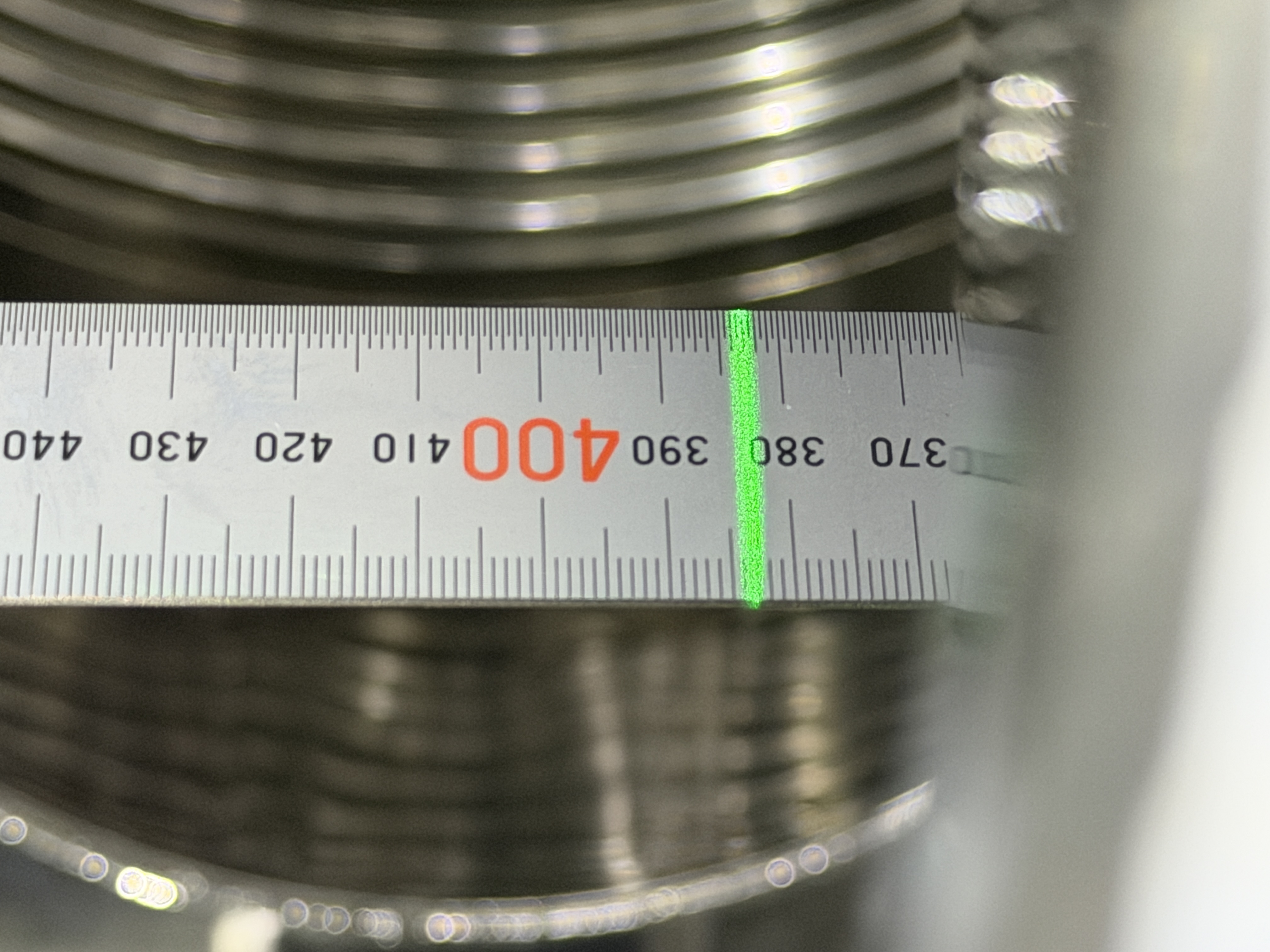
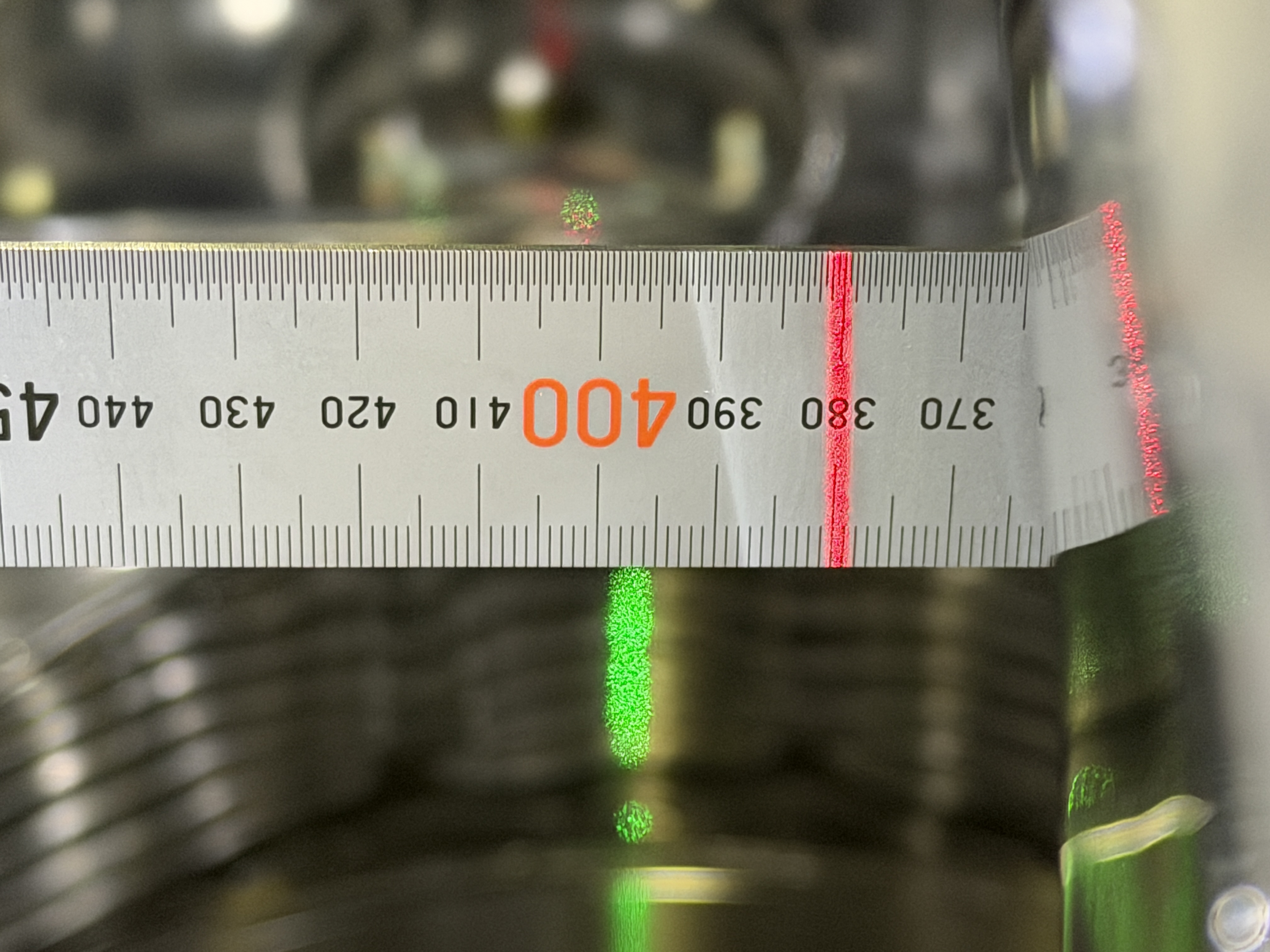
・Took some photos to chech thickness.
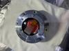
pic2: side view of new SRM mirror
pic3: side view of SRM-M mirror (old mirror)
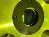
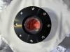
pic4: new SRM mirror Assy without shim plates
pic5: SRM-M mirror Assy without shim plates (old mirror)

・Takahashi-san measured thickness of both mirrors by vernier caliper gage. It was reported on klog36579.
・Takahashi-san talked with Ushiba-san, and we decided to re-assemble SRM-M again.

4. First contact: SRM-M mirror
・I put FC to the SRM-M mirror: AR and HR side. Procedure was same as "1. FC:new SRM mirror".

5. Assemble SRM-M mirror
・Procedure is the same as "3. Assemble new SRM mirror" up to a certain stage.
・Assemble parts#5 and parts#9(Shim-plates), tighten M3 screws with 0.6 Nm.

Images attached to this comment
ryutaro.takahashi - 22:48 Monday 16 March 2026 (36591) Print this report

[Takahashi, Washimi, Hirata]

We replaced the window mirror (SRM-W) with the 70% mirror (SRM-M). This is a demonstration for training in replacement. At the beginning, we confirmed the mirror's wedge direction: the X- side (Picture 1). We removed the black cylinder from the rear side and removed the mirror holder (Picture 2) by pushing with a Teflon bar from the rear side (Picture 3). We attached the assembled 70% mirror to the test mass (Picture 4), confirming the wedge direction (Picture 5).

We checked the extracted window mirror. The mirror thickness was 9.6mm at the wedge marker. Two 0.5mm shims were used as the spacer for the flange.

Images attached to this comment
ryutaro.takahashi - 17:19 Monday 23 March 2026 (36632) Print this report

[Hirata, Washimi, Takahashi]

We removed the 70% mirror (SRM-M) from the Al test mass (Picture 1). At the beginning, we removed the black cylinder from the rear side and removed the mirror holder (Picture 2) by pushing with a Teflon bar from the rear side. We put the extracted 70% mirror on the covered table (Picture 3).

Images attached to this comment
naoatsu.hirata - 23:49 Monday 23 March 2026 (36634) Print this report

[Takahashi.R, Hirata]
The SRM mirror was transported from Mitaka to Kamioka, and the wedge direction was readjusted.

・The SRM mirror was disassembled and the wedge direction was readjusted. (pic1)
・It was reassembled using a 1.4 mm shim. The specified tightening torques are 0.6 N·m for M3 and 1.5 N·m for M4.
・First-contact was applied to the HR side and then peeled off for cleaning. The process took about one hour. It was easier than when Aso-san peeled it off in Mitaka last week.
・The First-contact on the AR side was peeled off. It had been applied on Friday, March 13. We were concerned that it might be as difficult to remove as it had been from the HR side in Mitaka, but it came off very easily.
・First-contact was applied to the AR side again. (pic2)

Images attached to this comment
naoatsu.hirata - 17:45 Tuesday 24 March 2026 (36645) Print this report

[Takahashi.R, Dan.Chen, Hirata]
We installed new SRM mirror.

・The First Contact on the AR side was peeled off before installation.
・Confirmed that the wedge mark was on the -X side.
・Installed the new SRM mirror and tightened the M4 screws to 1.5 Nm.
・Peeled off the First Contact on the HR side.
・Inspected the surface and found some dots near the center. (pic1)
・We removed the mirror and applied First Contact again. (pic2)
・We reinstalled the mirror and peeled off the First Contact again. The second trial was successful, and the dots near the center were removed. (pic3)
・Finally, we confirmed that the wedge mark was on the -X side again. (pic4)

Images attached to this comment
dan.chen - 5:31 Wednesday 25 March 2026 (36650) Print this report
ryutaro.takahashi - 6:09 Wednesday 25 March 2026 (36649) Print this report

[Hirata, Dan, Takahashi]

After installing the new mirror, we released the suspension and the IP in the following order: TM, RM, IM, IRM, BF, F0, and IP. Then we tried to align the TM using the Oplev. Initially, the beam spot of the Oplev was at the upper right. We adjusted the horizontal position with the F0 yaw FR and the vertical position with the IM picomotor (moving mass). The TM was significantly deviated in the pitch direction (maybe due to the lighter new mirror), so 130,000 steps were necessary for the picomotor. We could find the beam spot on the QPD (Picture 1).

We closed the side hatch and the top chamber. The transfer function from the H2+H3 actuator for the IRM dampre to the Oplev yaw "IRM_OLDAMP_Y" was measured (Picture 2). Two modes at 60mHz and 160mHz can be confirmed.

Images attached to this comment
ryutaro.takahashi - 8:27 Thursday 26 March 2026 (36657) Print this report

[Hirata, Dan, Takahashi]

This is a log of the work on the 25th. We performed the following tasks:

  1. Checked the FLDACC signals.
  2. Checked the height of the TM/RM.
  3. Released the breadboard and checked the height.
  4. Adjusted the gaps of the EQ stoppers and took the pictures.
  5. Checked the cables at the feedthrough flanges.

Details will be reported later.

naoatsu.hirata - 16:42 Thursday 26 March 2026 (36662) Print this report

(Work on 25th, detail report)
[Takahashi.R, Dan.Chen, Hirata]

This is the detail report of as Takahashi-san's report in klog36657.

>2.Checked the height of the TM/RM
The center of the mirror was 2mm higher than the target on the SRM chamber.

1.We set up two laser levelers: green one on the +X side and red one on the -X side.
2.The green laser leveler was aligned with the mirror height target on the SRM chamber(pic1). The scratch line on the +X side is 1 mm above the green laser level line(pic2).
3.The red laser leveler was set on the -X side. The scratch line on the -X side is 1 mm above the red laser level line(pic3). 
4.The height difference between green laser leveler and red laser leveler was 2 mm.(pic4,5)
Conclusion: The +X scratch line was 1mm higher than target, and the -X scratch line was 3mm higher than the target. Therefore, the center of the mirror was 2mm higher than the target on the SRM chamber.

>3.Released the breadboard and checked the height.
The result was almost the same as previous measurement.

1.Two 5 kg masses were left in the position where the mid-size baffle had been installed. (Mid-size baffle were 4.94kg and 4.931kg. see klog36531) Those masses were fixed by M6 studbolts and nuts.(pic6)
2.We checked the height of bread board using laser leveler aligned with the target on the SRM chamber. The measurement point was approximately the same as in the previous measurement.klog36531
3.The result are as follows.
・+X side (Green line) : 383.5mm.(pic7)
・-X side (Red line) : 380.0mm.(pic8)
 *Note: The previous measurement values reported in klog36531 were reversed. Sorry for the mistake. Please check the pic7 and pic8 in klog3631)
4.We confirmed that nothing was blocking the oplev beam.(pic9,10)

>5.Checked the cables at the feedthrough flanges.
We checked in-vacuum cable connection. The result are attached.

Images attached to this comment
Non-image files attached to this comment
Search Help
×

Warning

×