Reports 1-1 of 1 Clear search Modify search
VIS (SRM)
naoatsu.hirata - 19:27 Monday 09 March 2026 (36531) Print this report
IRM damper installation

[Takahashi, Washimi, Hirata]


We did preparation for installation of SRM IRM dampers.Today, we locked suspension, and Breadboard. After that we removed Mid-size baffles from the breadboard.

1. Lock IP and Topfilter
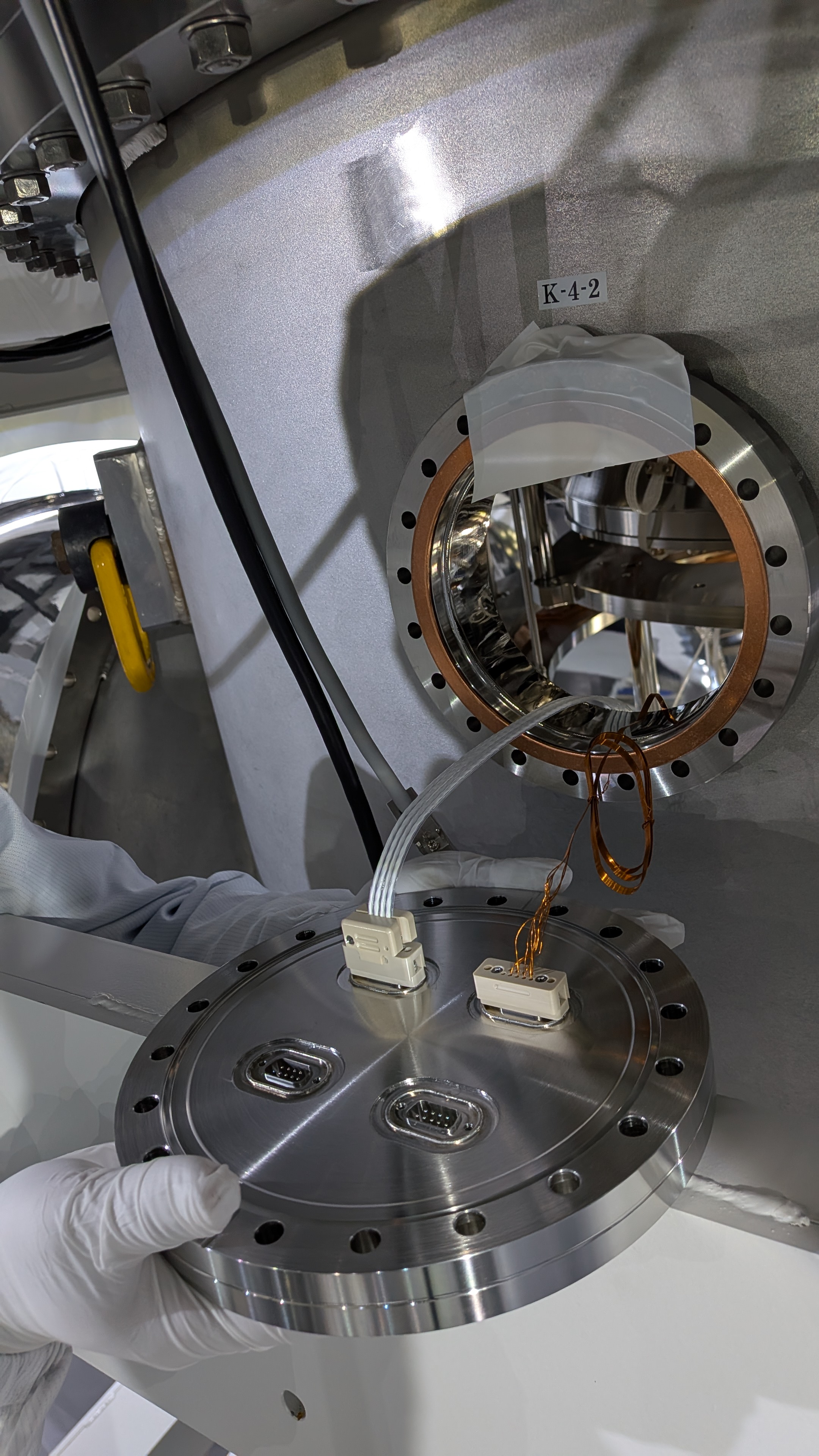
After opening the top flange of chamber, we locked IP and Topfilter. We covered suspension by Seiden-sheet. (Guardian status was already SAFE mode.)

2. Check the mirror height
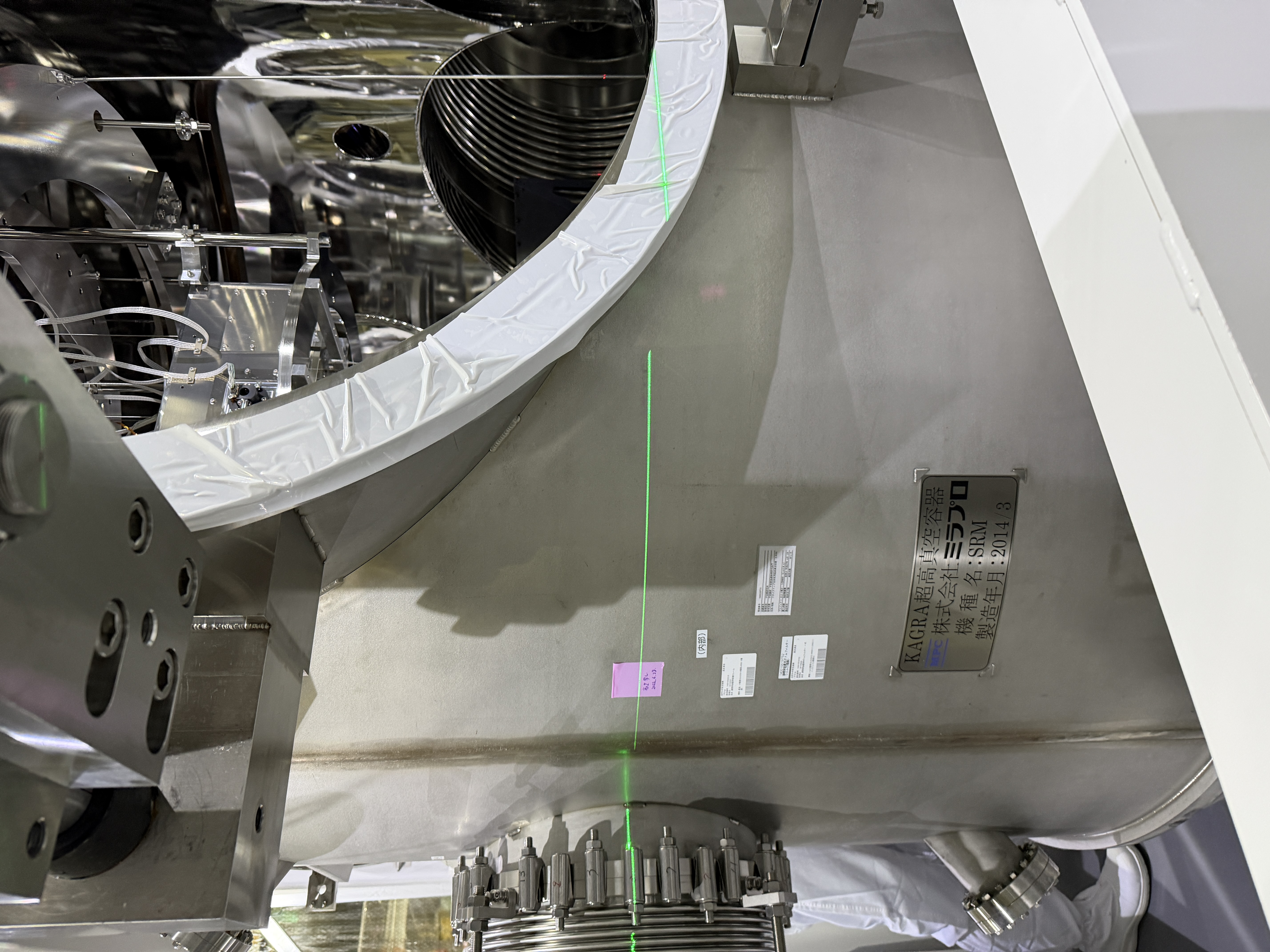
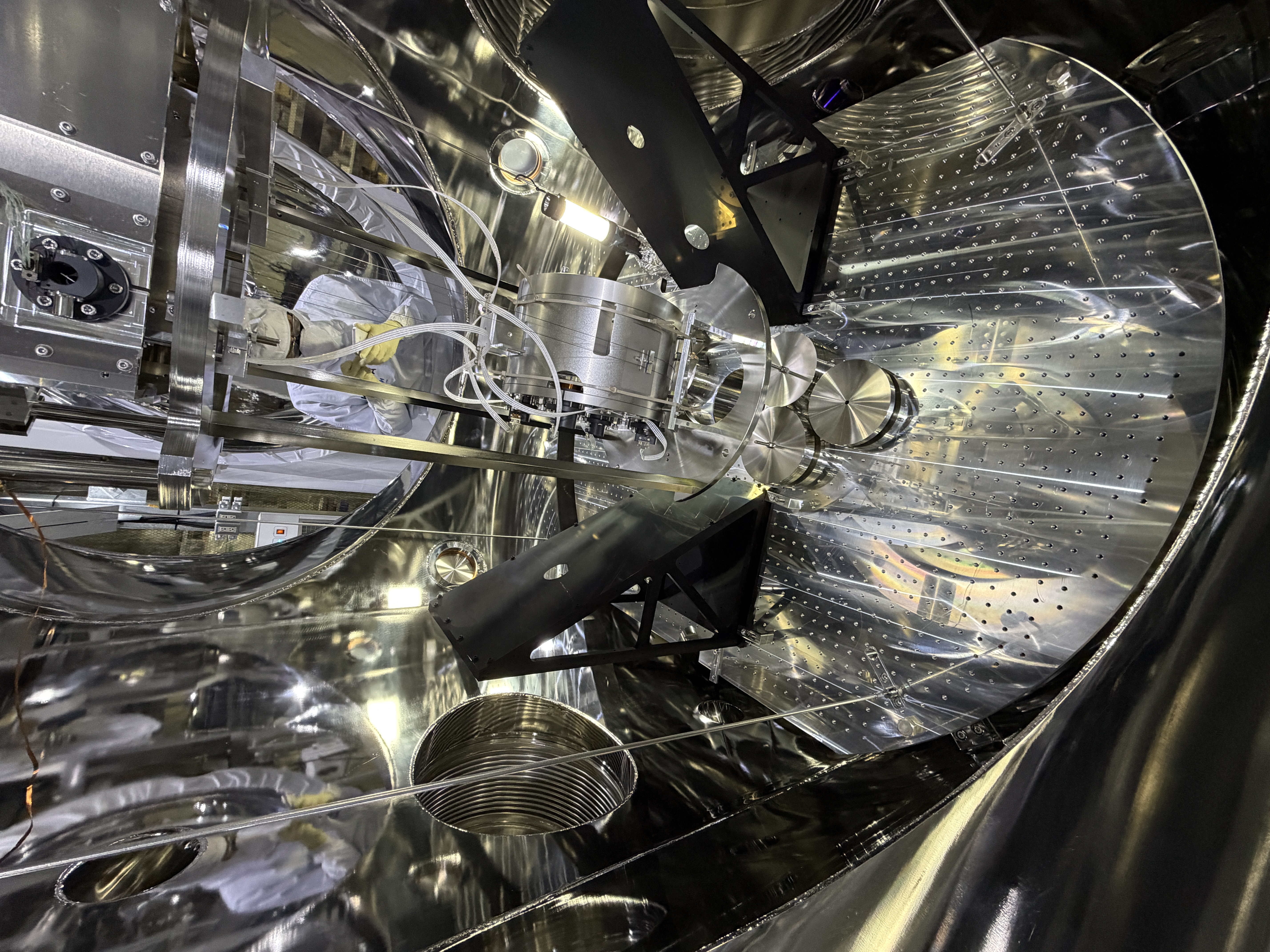
We checked the mirror height by laser leveler. Beam height is indicated on SRM chamber(Main mark is on +Y+X side. Copy is on -Y+X side. pic1, pic2 )
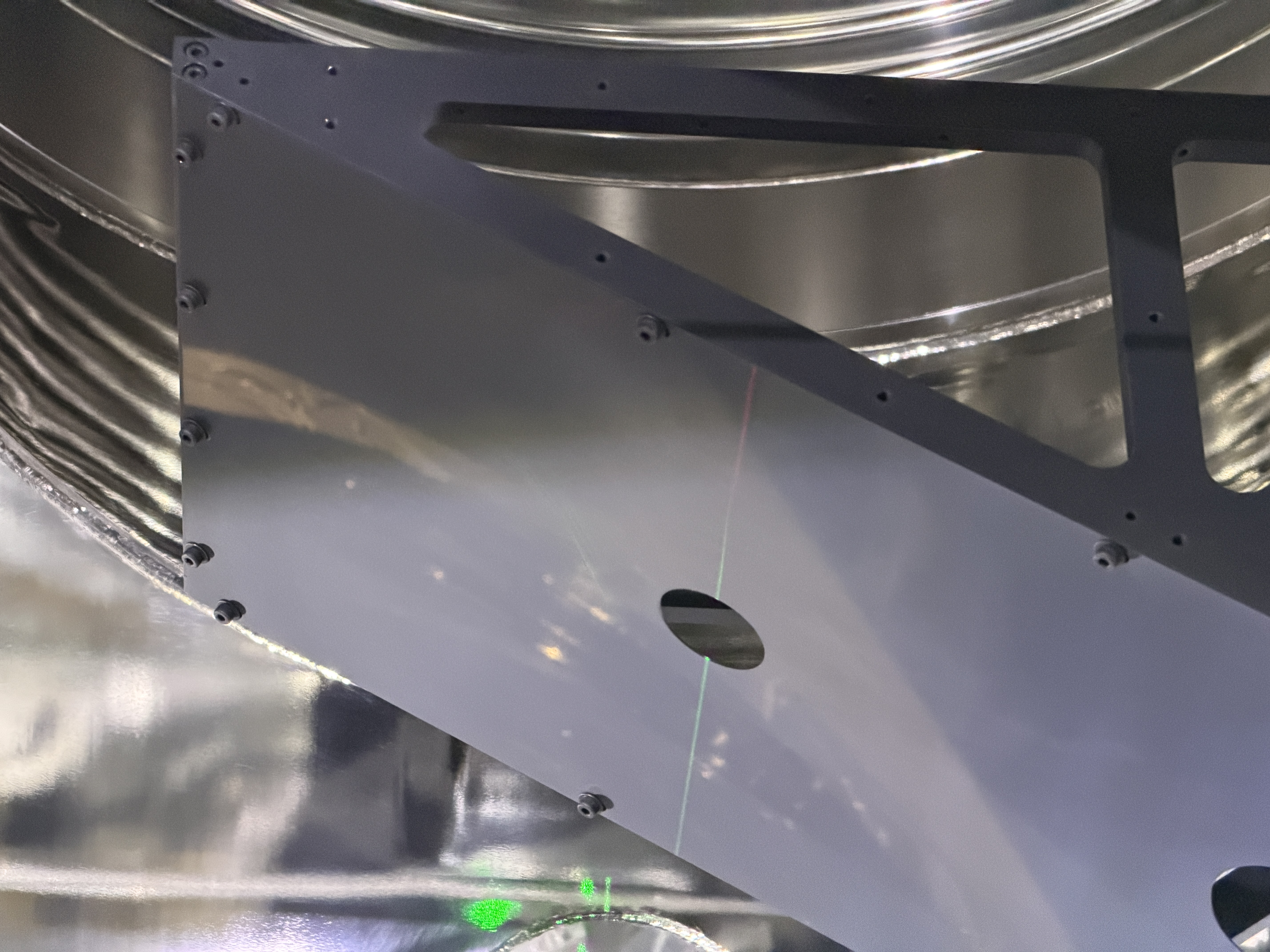
Unfortunately, Beam height is close to the edge of side flange. So laser leveler could only be used near the center.(pic3) We put green laser leveler at the +X side, and align to the Beam height mark on the chamber.
And put red laser leveler at -X side, and align it to the +X side green laser leveler(pic4). Recoilmass front ring has center mark. We can see the laser leveler height and the recoilmass center line.

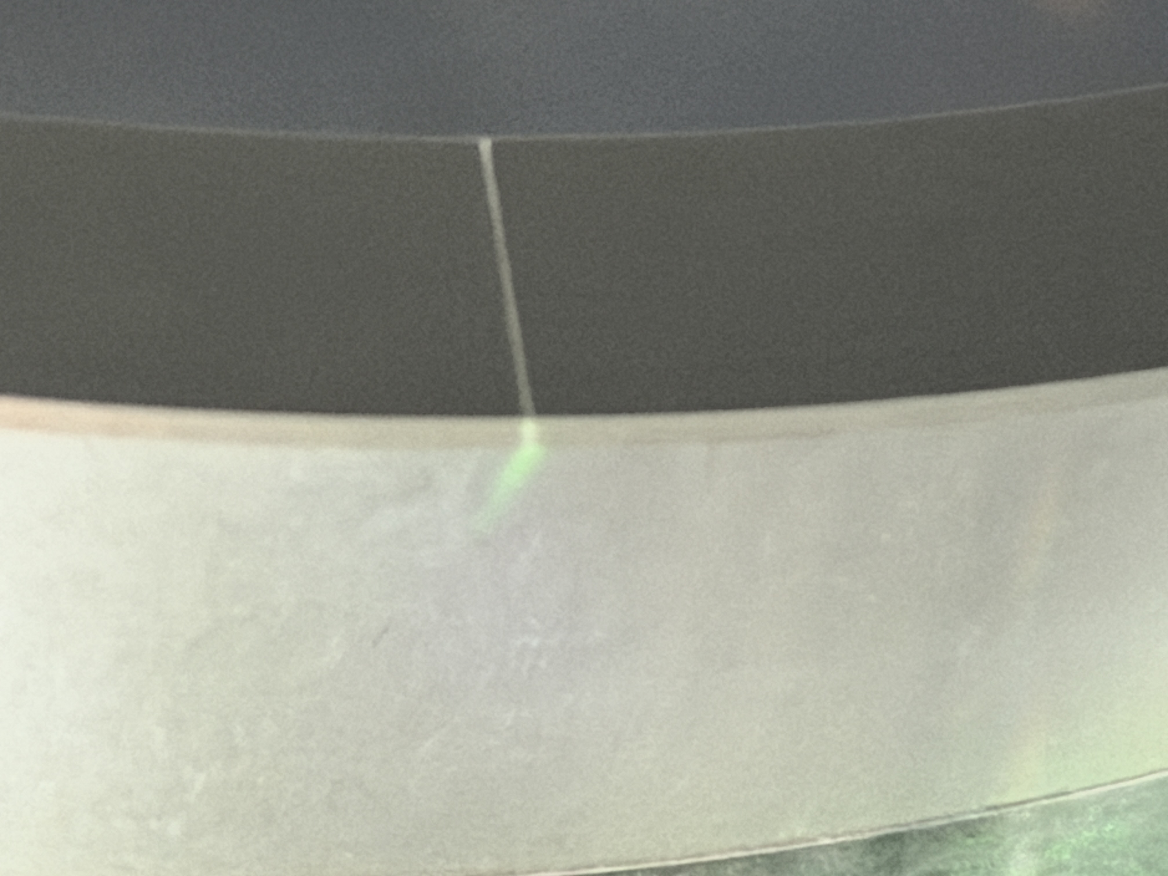
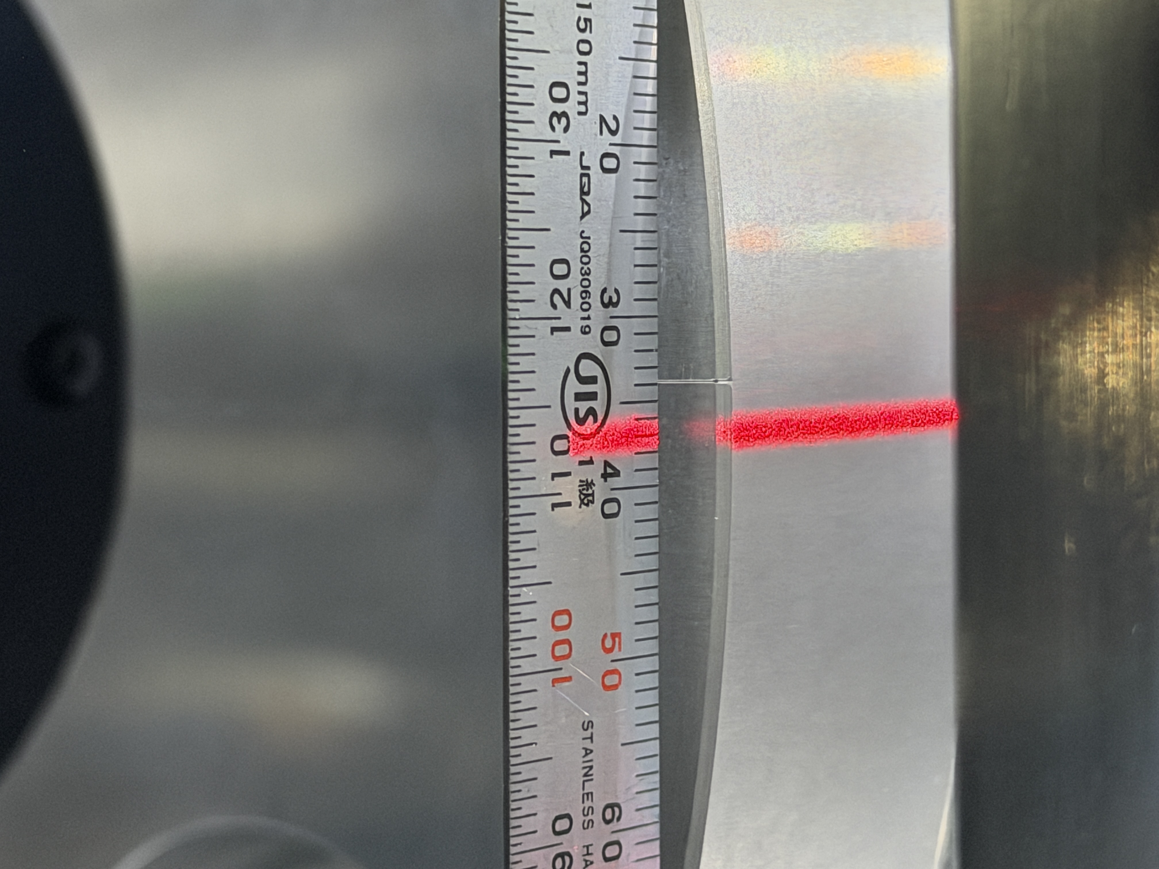
・+X side (Green line) looks same as recoilmass center line.(pic5)
・-X side (Red line) looks 3 millimeters away from the recoilmass.(pic6)

3. Check the Bread board height
Laser leveler can only used around center of side flanges. So we can only check the height near the center.

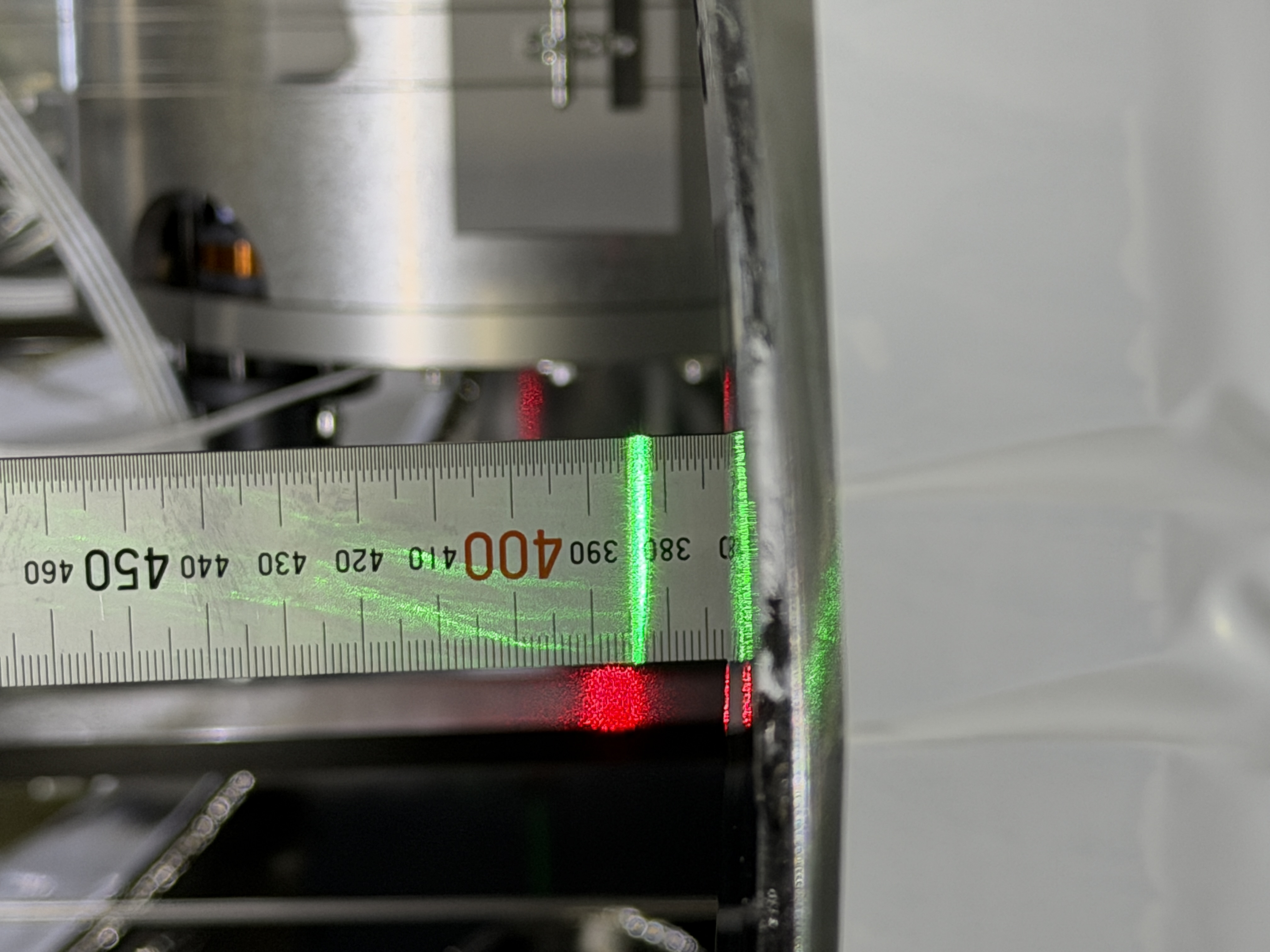
・+X side (Green line) is 380.5mm.(pic7)
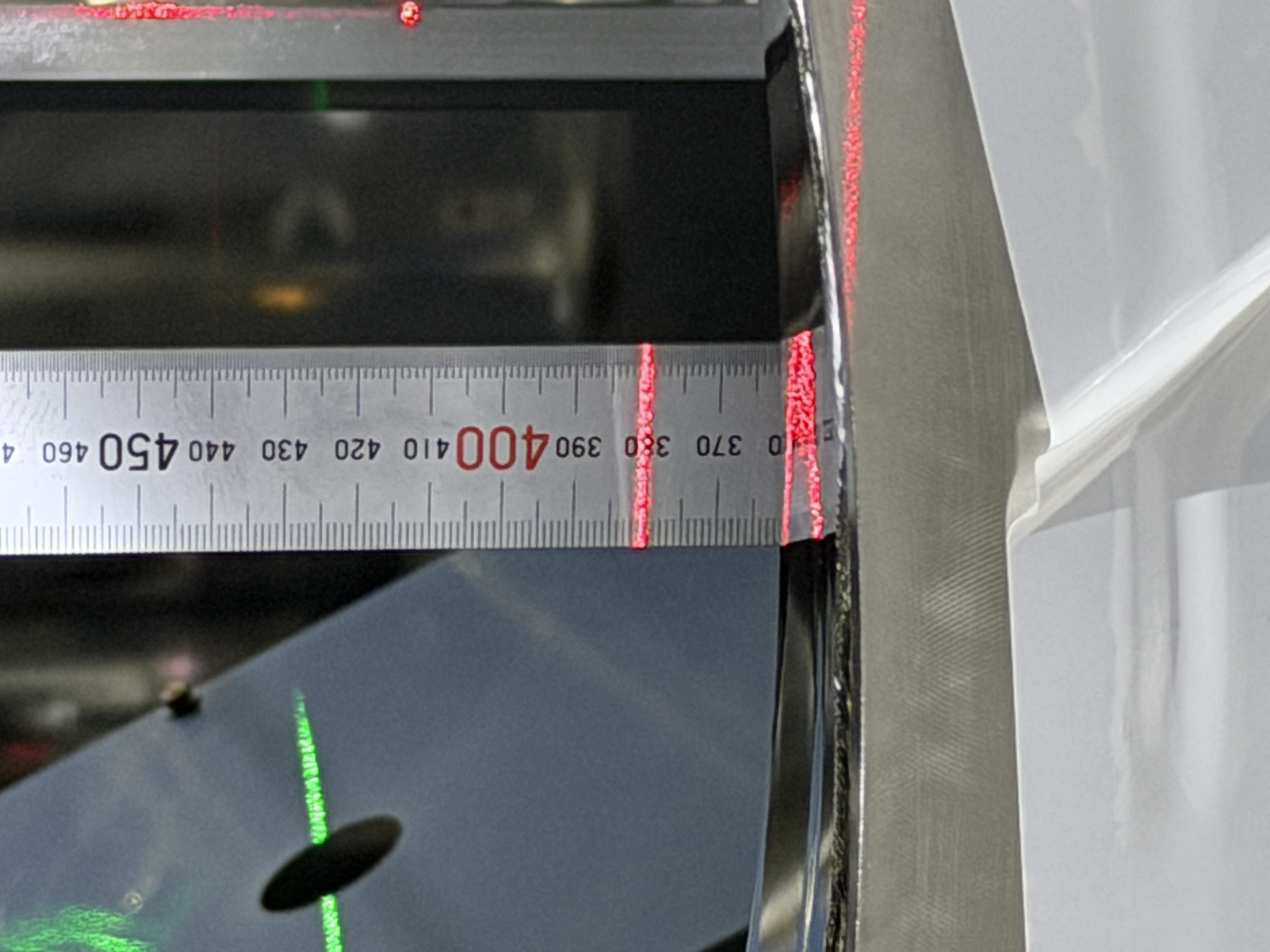
・-X side (Red line) is 383.0mm.(pic8)

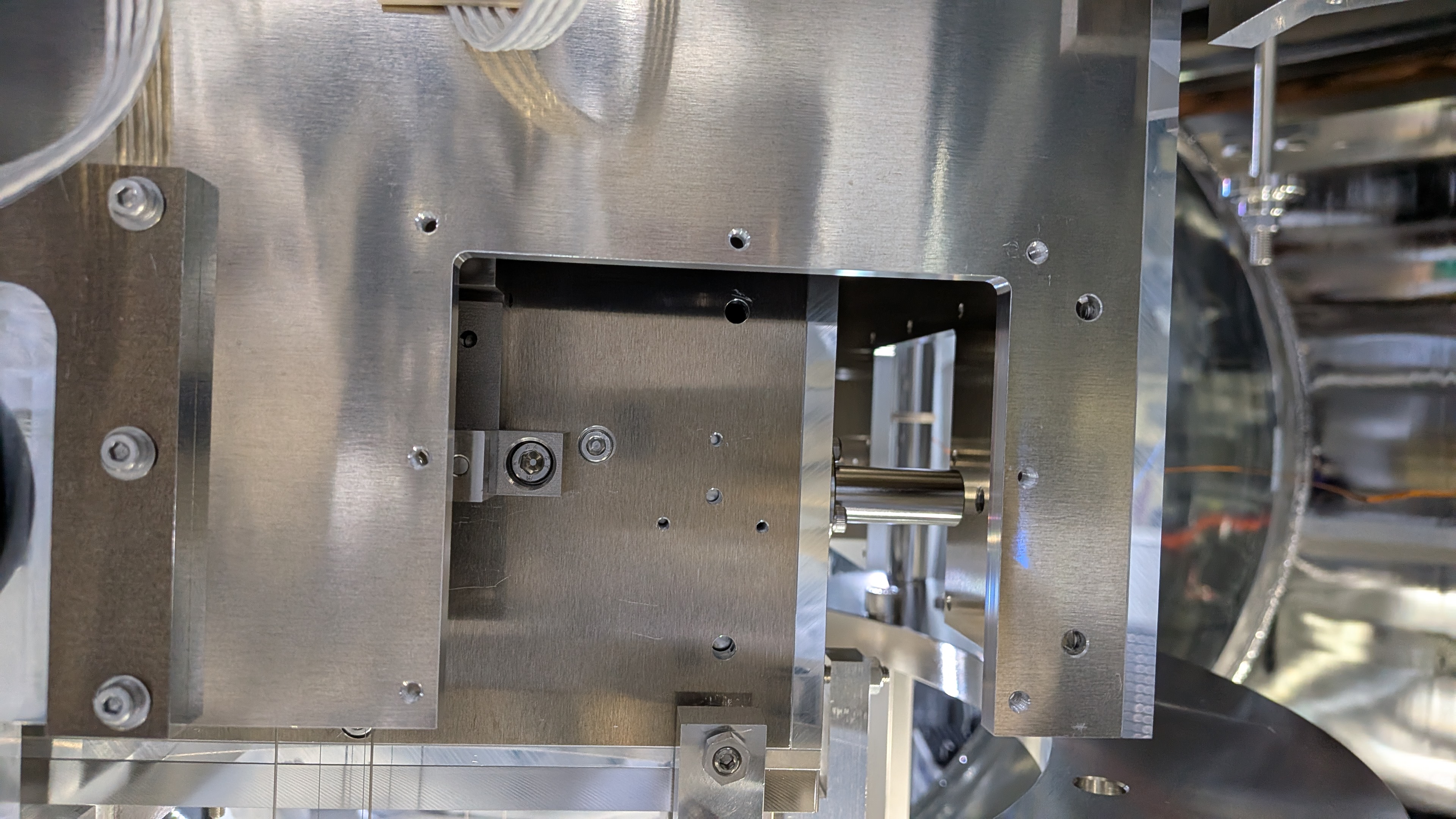
4. Lock the Breadboard
Turn 4 foot screws to lower  that until they touch the block. After that, added 4 masses(Total 20kg) on the breadboard for locking. (pic9)

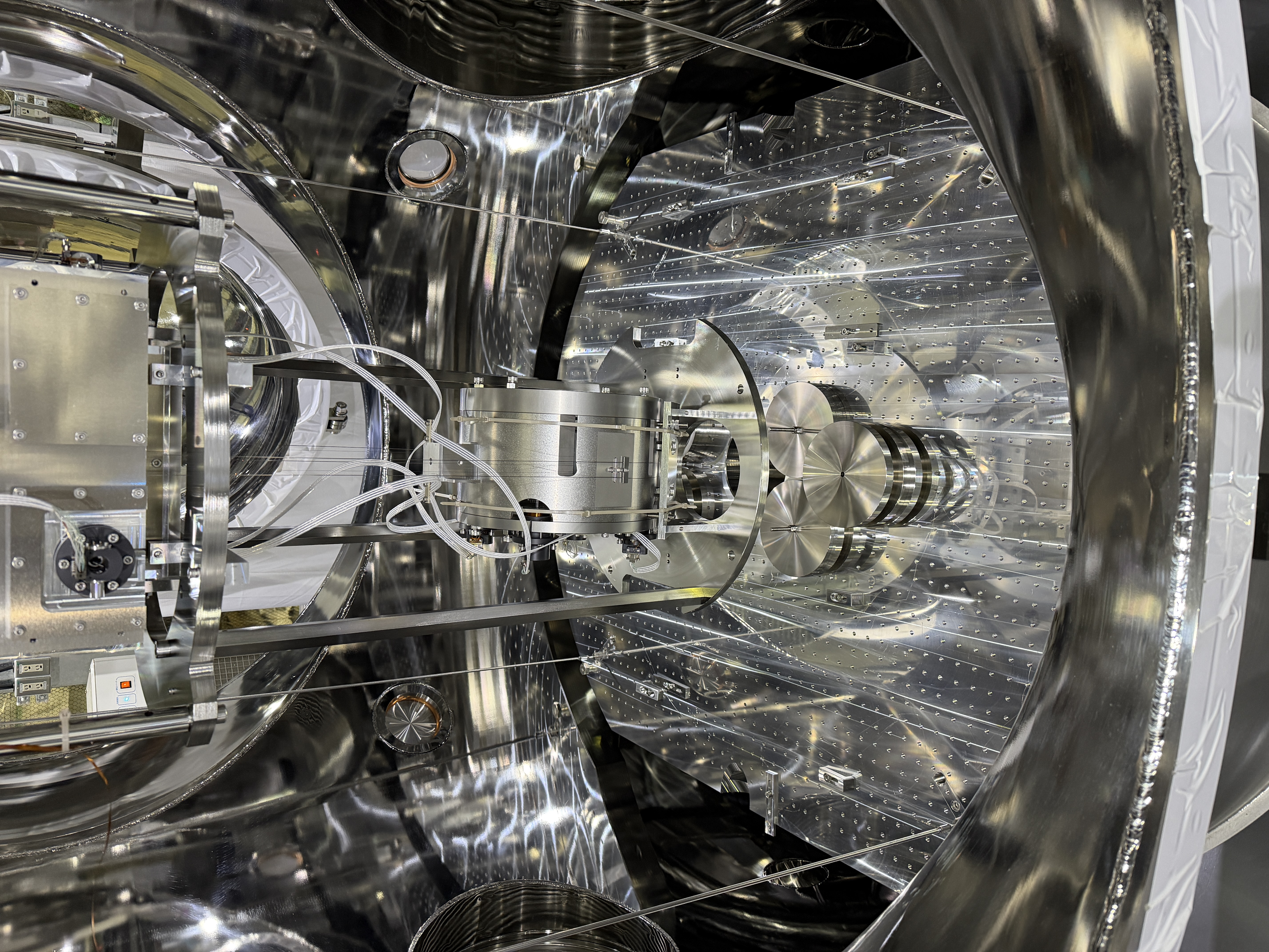
5. Lock the Suspention
Bottomfilter, IMR, IM, RM and TM were locked.

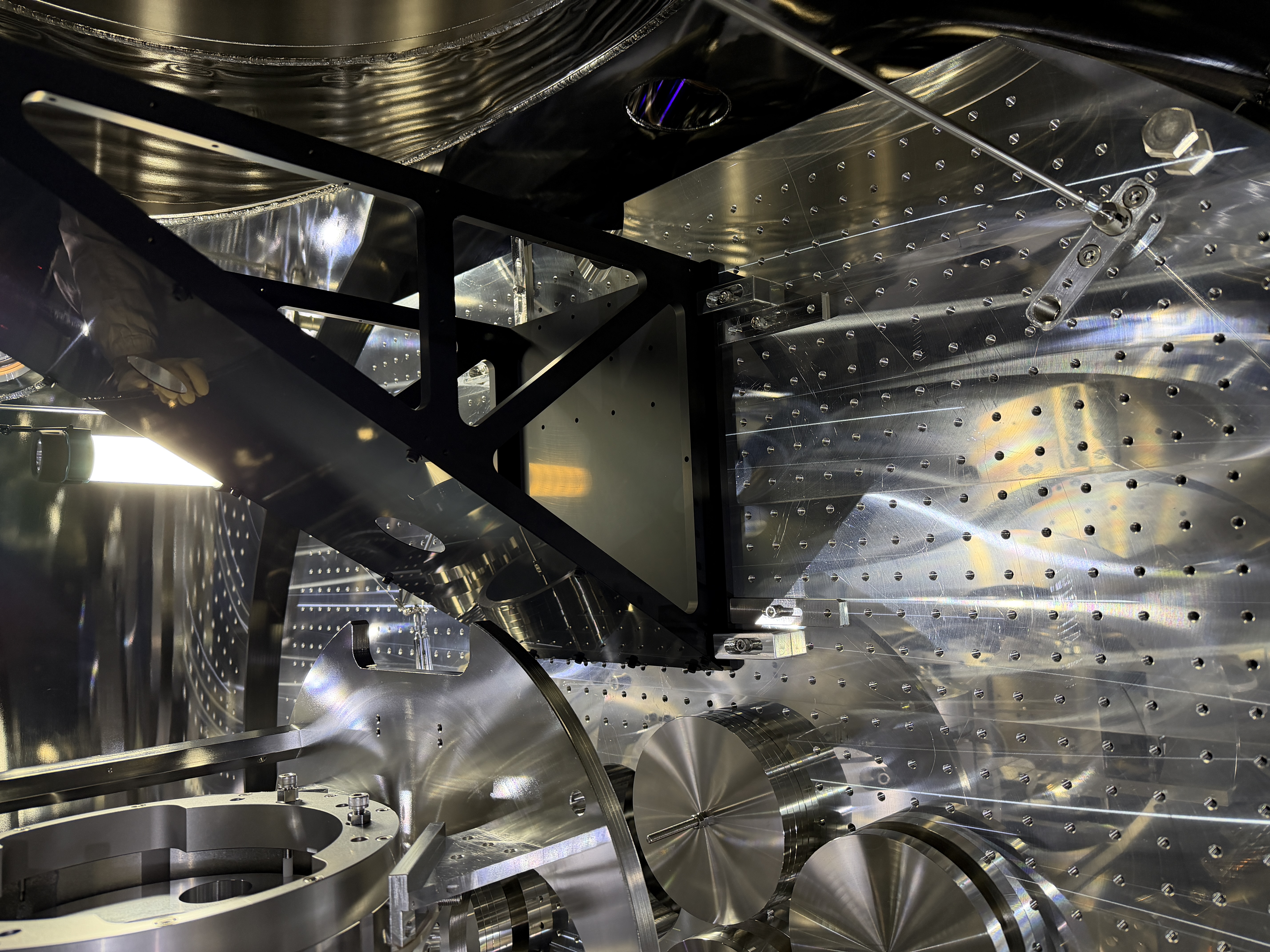
6. Mark the Mid-size baffle position
To record the current baffle positions, 3 blocks(AL clamps) were set on each baffle.(pic10)

7. Remove Mid-size baffles
We removed 4 fixed clamps, and removed mid-size baffles(AR side and HR side). Clamps for the mid-size baflles remain on the bread board.(Note that those positions have been changed.) (pic11)
Removed Mid-size baffles are on the tables have 4 pillars, and wrapped by plastic films. 4 pillars preventing plastic film touch baffles. (pic12)

*We weighed removed baffles.

・HR side : 4.94kg
・AR side : 4.931kg

Today's pictures are https://www.dropbox.com/scl/fo/1dw0adstbz35z85i0vd91/AJlOguQbuxD332fX1ZaIiYE?rlkey=xv1ztcd0wli70ukd0hxlslcl0&st=sfhiadap&dl=0

Images attached to this report
Comments to this report:
naoatsu.hirata - 18:37 Tuesday 10 March 2026 (36537) Print this report

[Takahashi.R, Washimi, Hirata]

We have completed the installation of the IRM damper’s mechanical parts and in-vac cabling. Suspention is still locked, so we have not operated IRM damper yet.

1. Exchange dummy plates to magnet plates
IRM has 3 dummy plates. We removed them(pic1). After that, we assembled the plates with the IRM, which already had the magnets glued on by Takahashi-san. (klog 36517)(pic2)

2. Install coil base
Only coil base part are installed first.(pic3)

3. Install coils
3 coils are connected to 1 cable. Pins and sockets are covered by PEEK shrink(pic4). 3 coils are installed at the same time. (pic5)
The cables got tangled, and it took  a while to untangle them. The relay connector was mounted on a nearby pole, and cable from the coil was connected to it.(pic6)
We checked resistance at the relay connector.

・Coil #1: 6.3 ohm
・Coil #2: 6.5 ohm
・Coil #3: 6.3 ohm

4. Coil alignment
Coil base can move 3 degrees of freedom, and coil 's angle can be adjusted using 6 screws. 3 Coils are aligned with magnet using those mechanics.

5. Exchange Feed through panel
We replaced the feedthrough panel, which previously had only thermometer connected, with 4 connector feedthrough. (pic7)

6. Continuity check
After connecting all in-vac cables, we did continuity check at the outside of feedthrough.(pic8)

・Coil#1: 7.6 ohm
・Coil#2: 7.9 ohm
・Coil#3: 7.7 ohm

We checked thermometer cables too.
・Thermometer1-6: 111.1 ohm
・Thermometer2-7: 111.5 ohm

Today's photo is here: https://www.dropbox.com/scl/fo/0lwieoxtf72h3d59xim6g/AMqNUPbwqT_vkmvjlaAGhMk?rlkey=scefj78rth7kpcsnq352ibedp&st=6qtyal01&dl=0

Images attached to this comment
naoatsu.hirata - 12:32 Wednesday 11 March 2026 (36545) Print this report

This is additional information: SRM IRM damper pin assignment is as follows.

H1(-Y side, Coil#1) : 1-6
H2(-X side, Coil#2) : 2-7
H3(+X side, Coil#3) : 3-8

tomotada.akutsu - 16:22 Wednesday 11 March 2026 (36548) Print this report

By the way, can you make sure to the relation of the pins and the coil wire-winding directions?

ryutaro.takahashi - 22:44 Wednesday 11 March 2026 (36553) Print this report

I checked the actuation of the IRM damper using the IM OSEMs. The DC actuation was confirmed with the offset (10000 count) to each COILOUTF (H1, H2, H3). Transfer functions from each actuator to the IM OSEMs were measured.

Images attached to this comment
naoatsu.hirata - 9:17 Thursday 12 March 2026 (36546) Print this report

[Takahashi.R, Washimi, Hirata]

We confirmed that IRM damper works well. After that, we locked suspention again.

1. Release suspention
BF, IRM, IM, RM and TM are released. IP and Topfilter were locked.

2. Check IRM damper position
Fortunately, IRM damper position looks almost same as before releasing suspention.

3. Check motion of IRM damper
First, we tried to check the damper motion, but it seemed that the damper was not working.
Takahashi-san inspected the area outside the SRM rack and found that the cross‑cable used between the feedthrough and the D‑sub cable was not appropriate.
After we replaced the cross‑cable, Takahashi-san confirmed that the IRM damper was working properly using the OSEM signal.

4. Transfer function
Takahashi-san will report later.

5. Lock the suspention
BF, IRM, IM, RM, TM were locked again.

6. Fasten feedthrough flange
We tighten feedthrough flange bolts(K-4-2). 10Nm→15Nm, 2times.

Today's photo is here: https://www.dropbox.com/scl/fo/ljozph0rohm3n46sp2ewj/ACaU31NZxhAETiqBB0v-Ras?rlkey=akuabdr9t2kroq02a5ae85t08&st=wy6asdyg&dl=0

*Sorry, I don't have any information about the relation of the pins and the coil wire-winding directions now. I will ask Takahashi-san.

Search Help
×

Warning

×