Reports 1-1 of 1 Clear search Modify search
VIS (EX)
takahiro.yamamoto - 14:44 Friday 28 March 2025 (33152) Print this report
Installation of Coil Driver Switcher

[Yokozawa, YamaT]

Abstract

We installed Coil Driver Switcher for the TM stage of ETMX.
Now we can reach LOCK_ACQUISITION state and excite the TM stage only via HPCD.
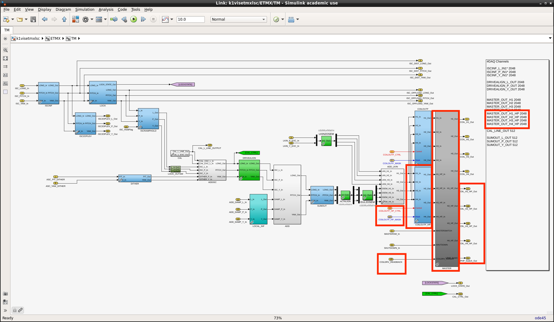
For switching LPCD, model update is required (maybe on the next maintenance day?).
 

Details

Installation of Coil Driver Switcher board
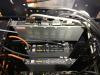
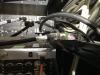
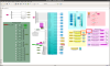
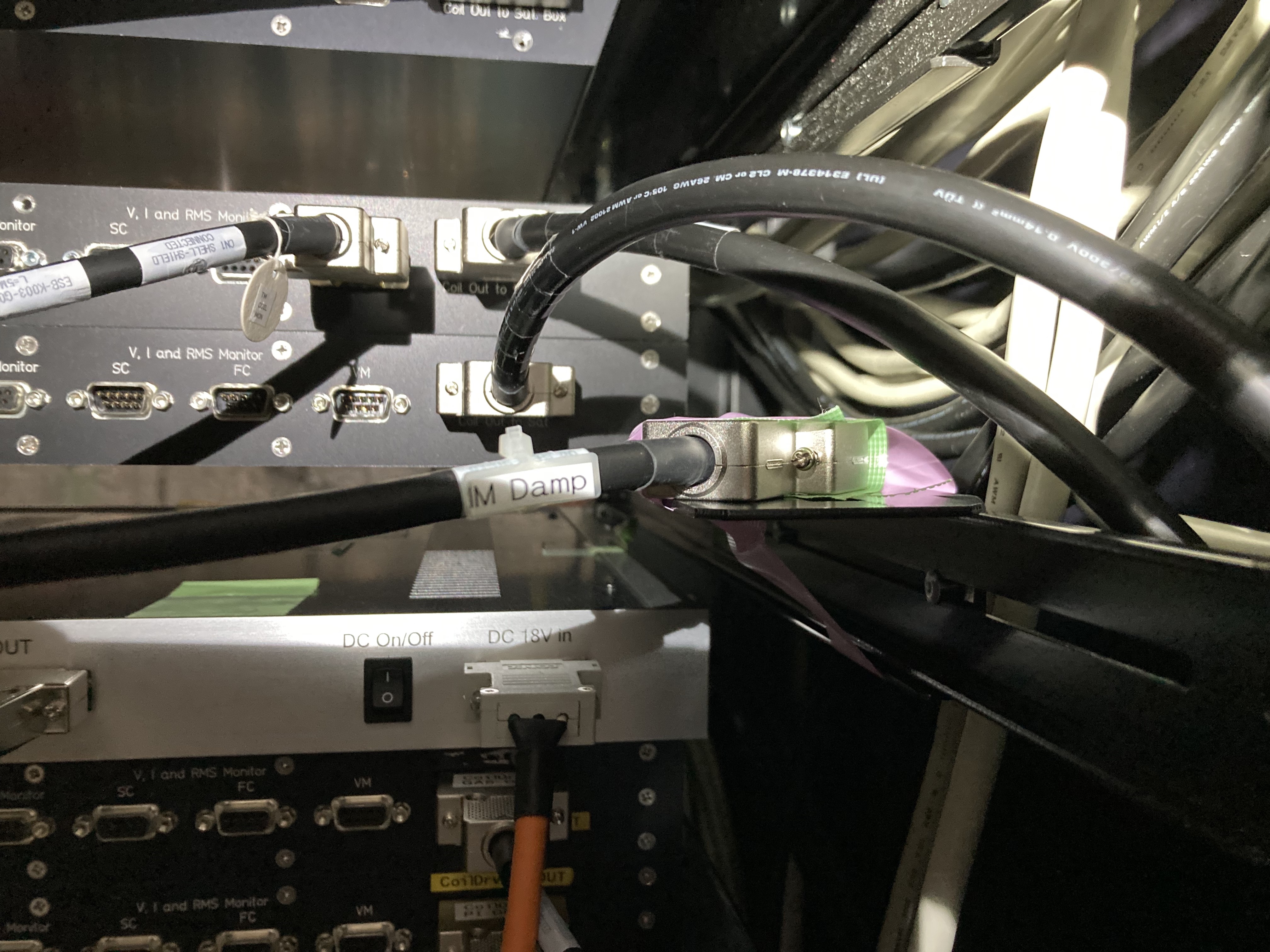
As an operation test of the Coil Driver Switcher was completed in klog#32943, we installed it for ETMX_TM. The Coil Driver Switcher hasn't been assembled to a formal chassis yet, S-number is not assigned for the chassis. A S-number of the used circuit board is S2516468. After preparing front/rear panels and a formal chassis, it should be replaced for a proper management of S-number for installed circuits. From the view point of gain adjustment, coil balance, and calibration, it may be better to keep using the same board until finishing O4c. S2516468 was installed rear side at U42 of EXV2 rack as shown in Fig.1. Output port of this board is connected to the feedthrough at the EXV chamber (a cable which had been connected to the output port of TM HPCD was moved to the output port of this board).

Connection with Coil Driver chassis
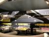
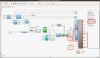
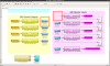
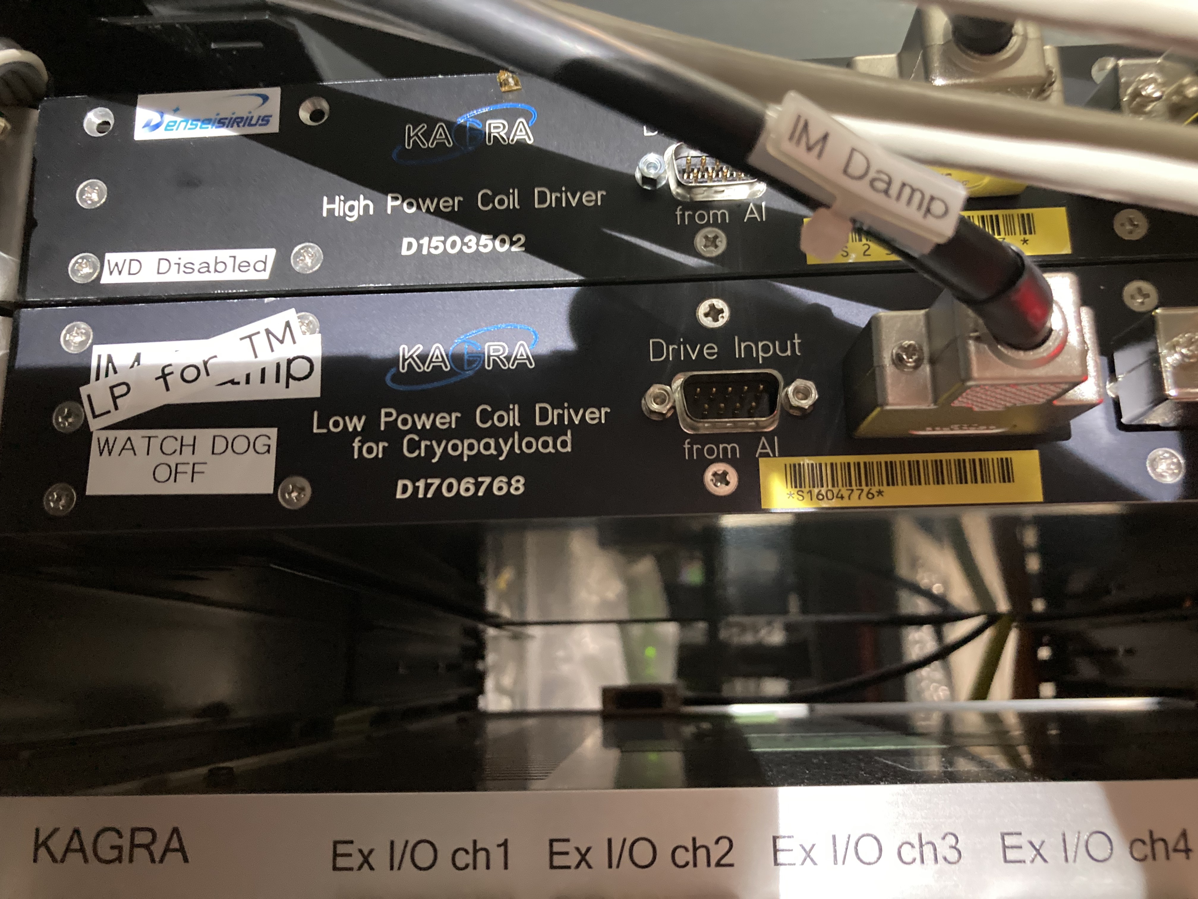
Two DB9 inputs of this board are connected with the output ports of TM HPCD and TM LPCD for CRYp. HPCD (S2315283) has been used in the past and wasn't changed in this work. LPCD for CRYp (S1604776) which had been installed for the IM blade damp and hasn't been used until today was reused for this purpose (see Fig.2). So there is no new installation of the coil driver chassis.
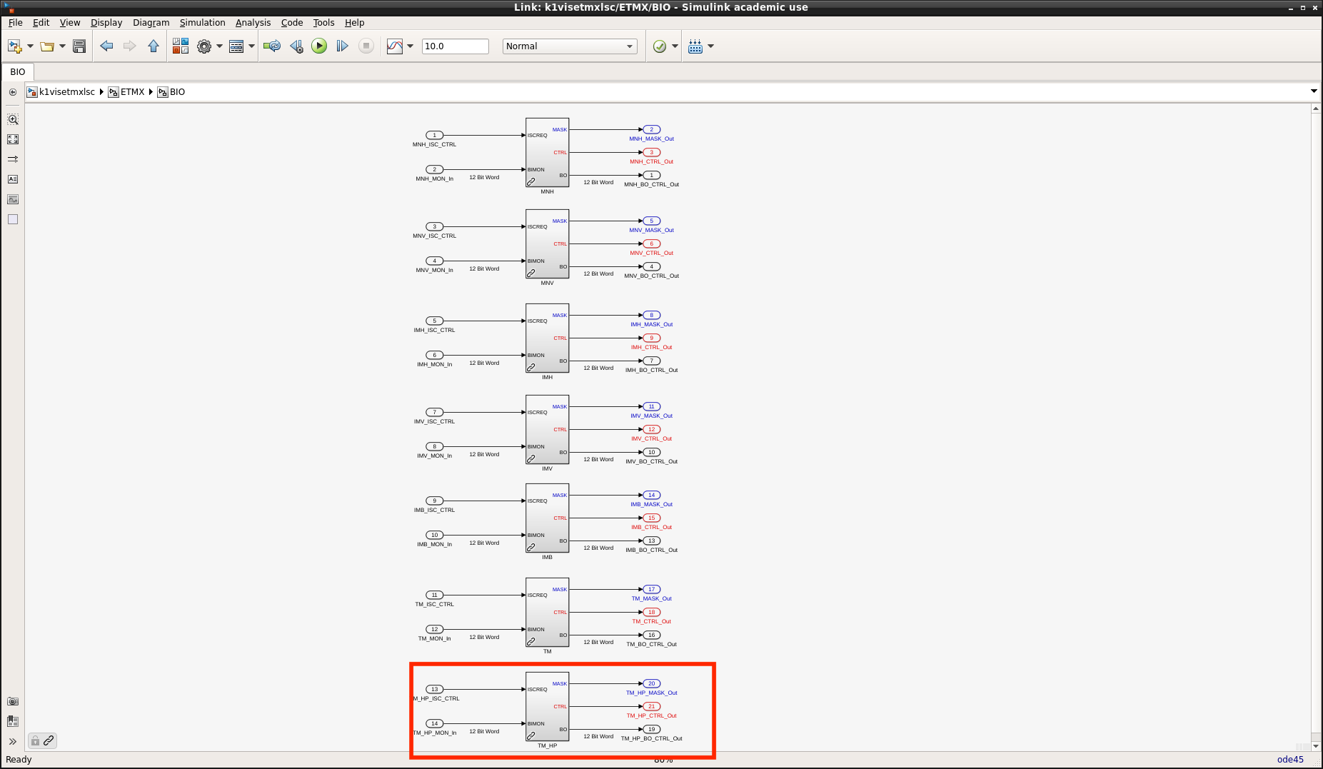
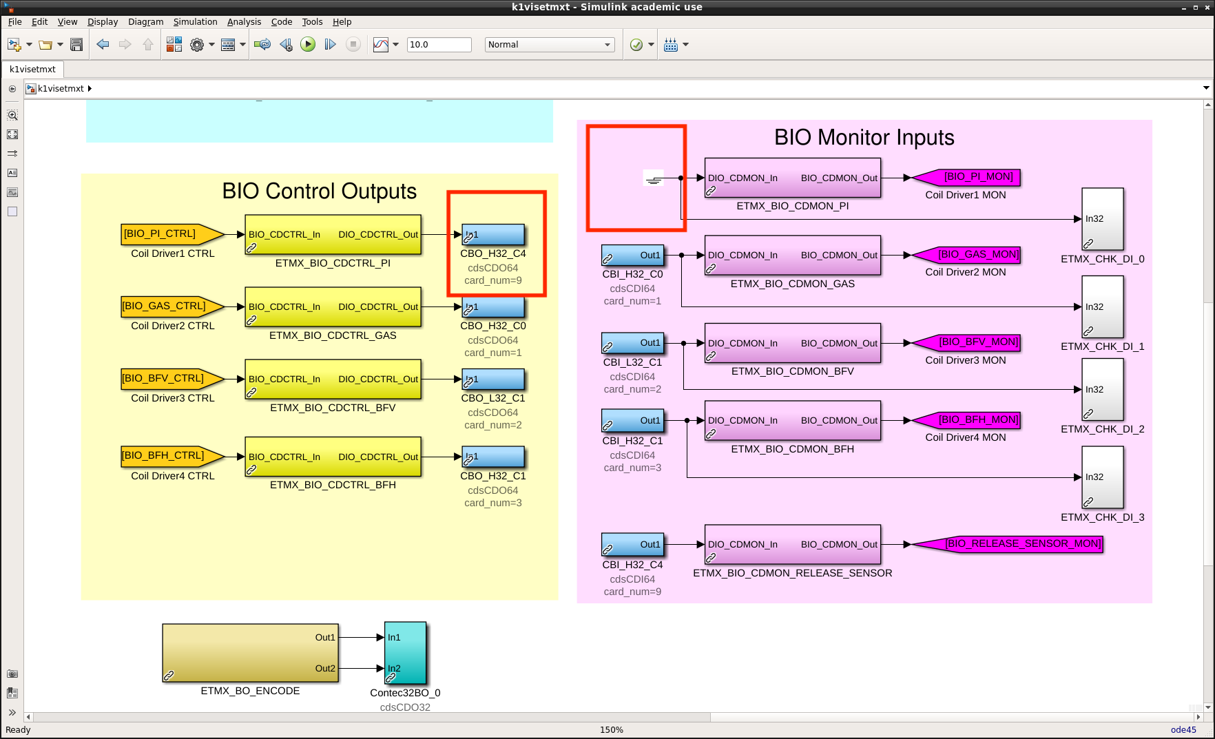
BIO cables
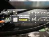
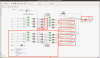
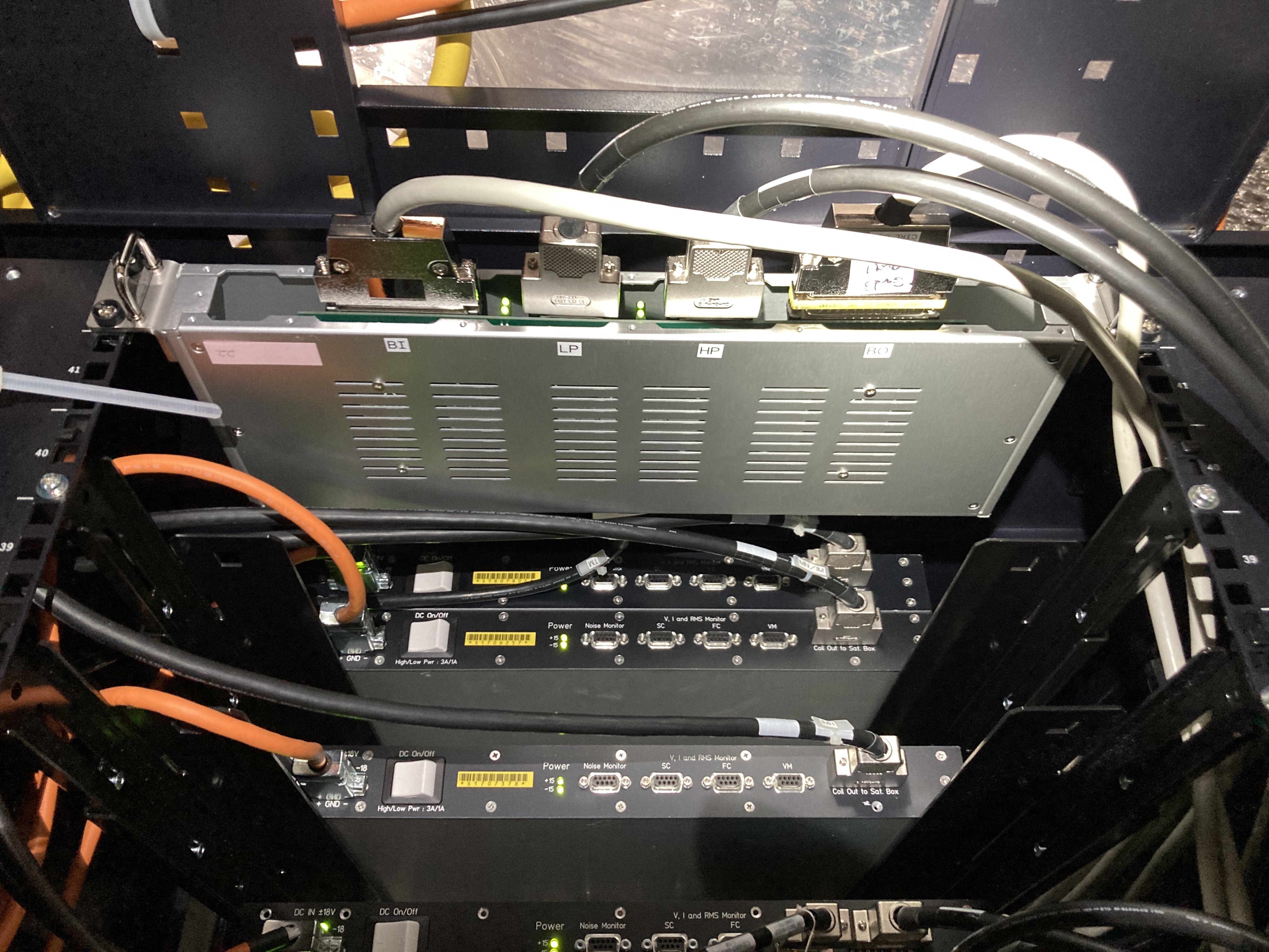
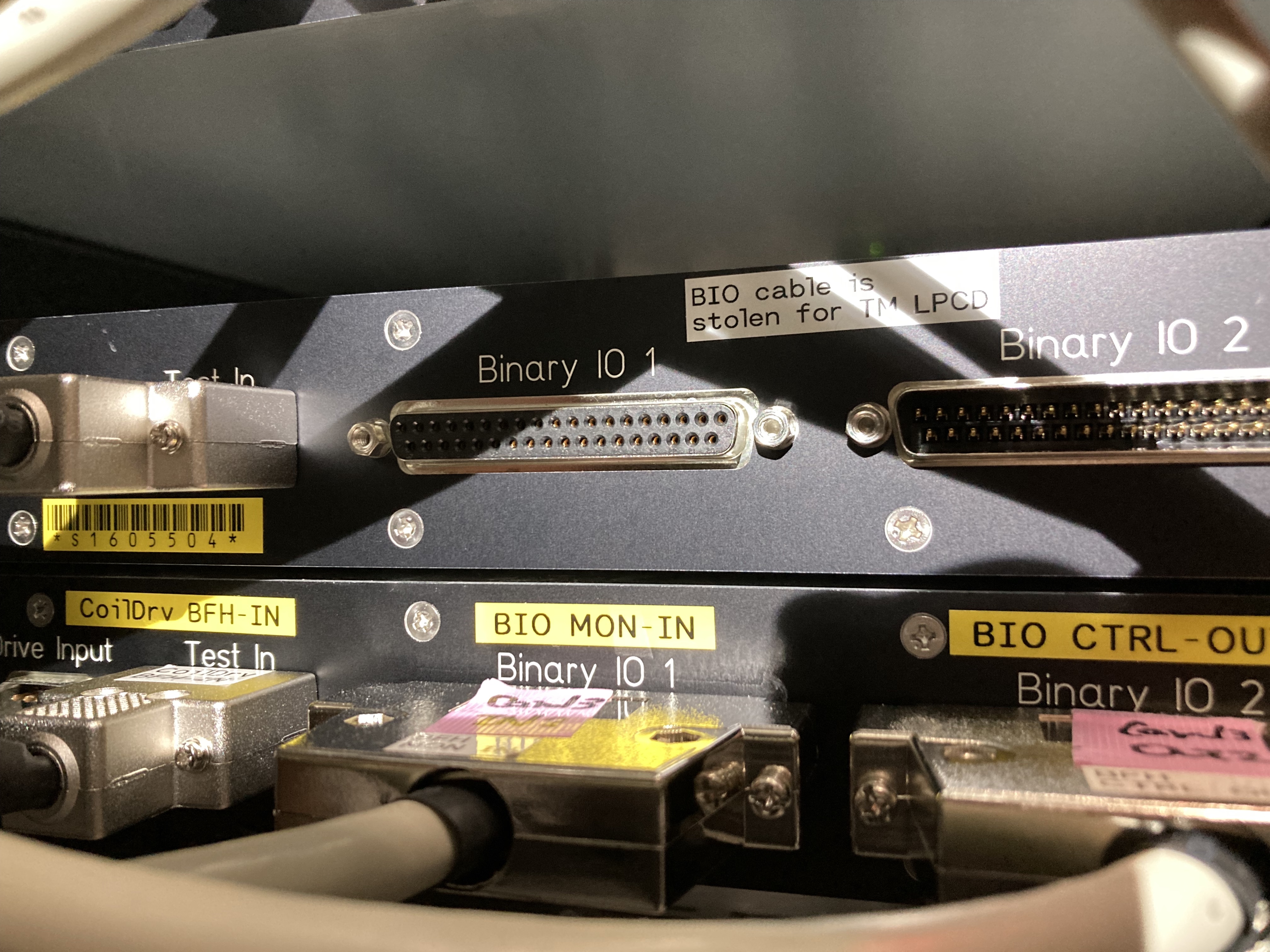
BIO cables were stolen from ones for BFV coil driver chassis for this purpose (see also Fig.3). Though we cannot enable the de-whitening filters for BFV now, it should be no impact for the daily operation because we haven't used de-whitening filters for the tower stages. k1iopex1 has now 5 BIO cards and one more BIO card may be able to be installed. If we will try it and will return stolen BIO cables to BFV, we probably need a whole day as a maintenance time.

Operation check
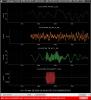
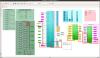
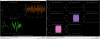
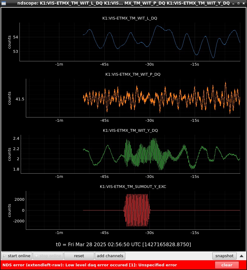
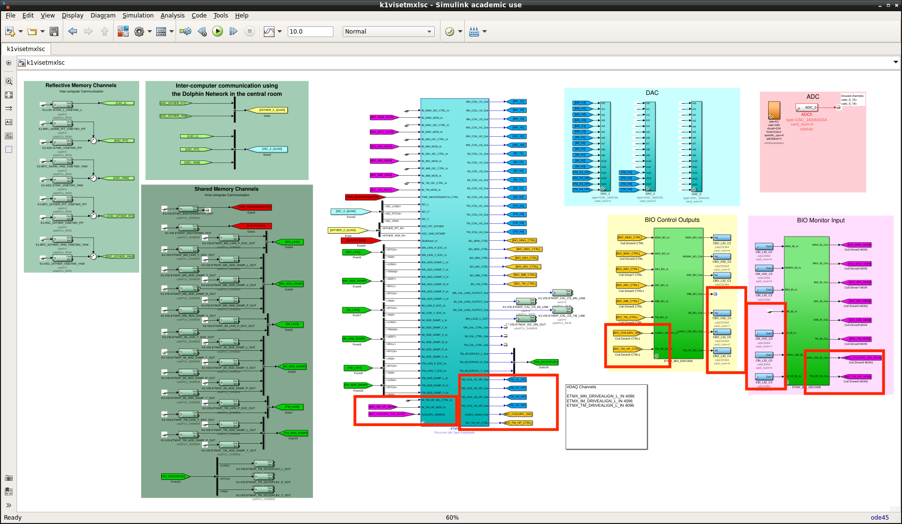
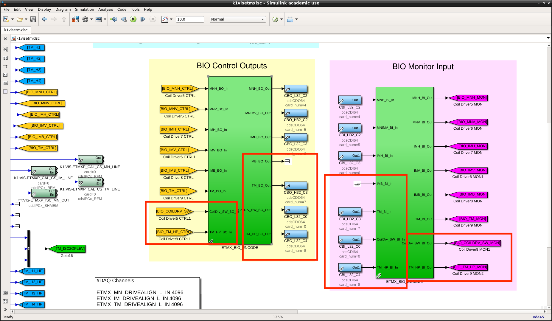
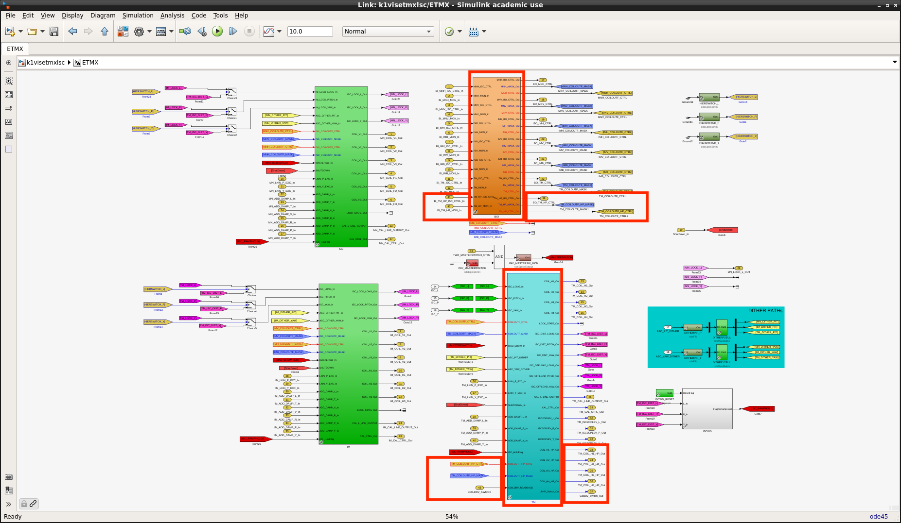
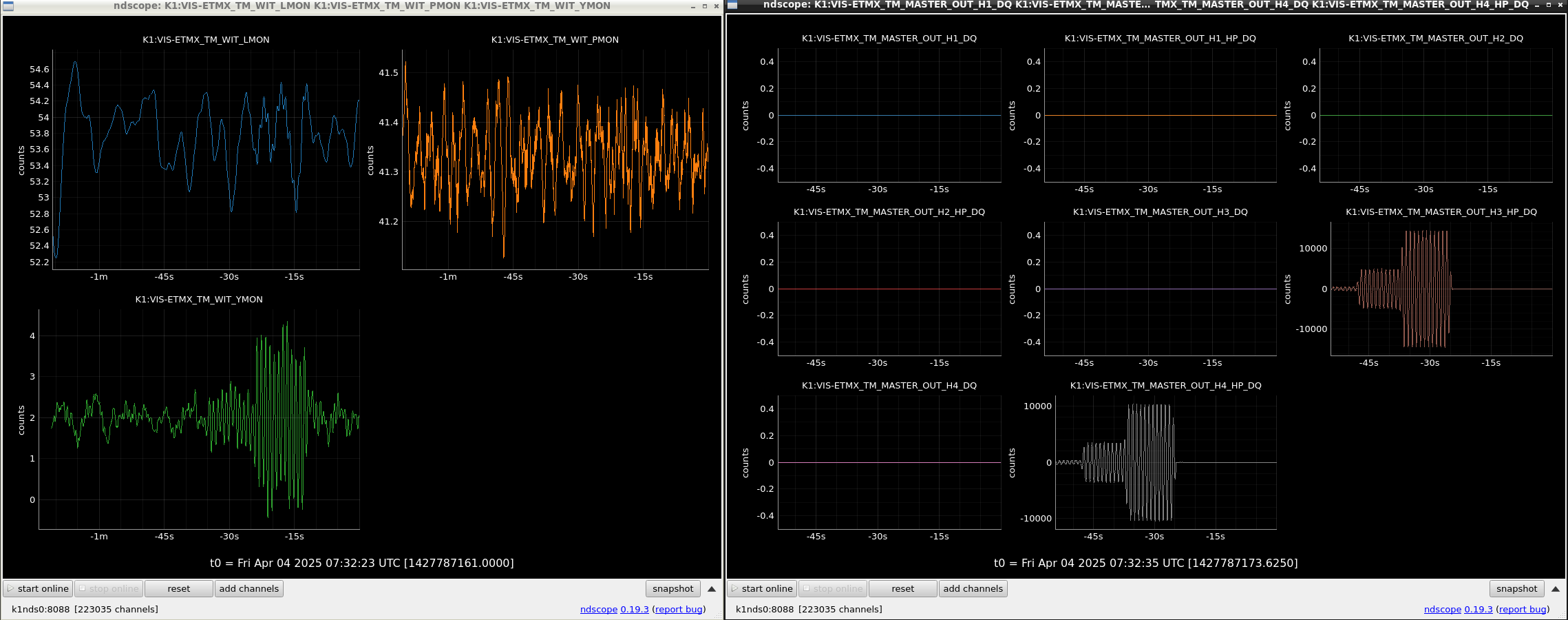
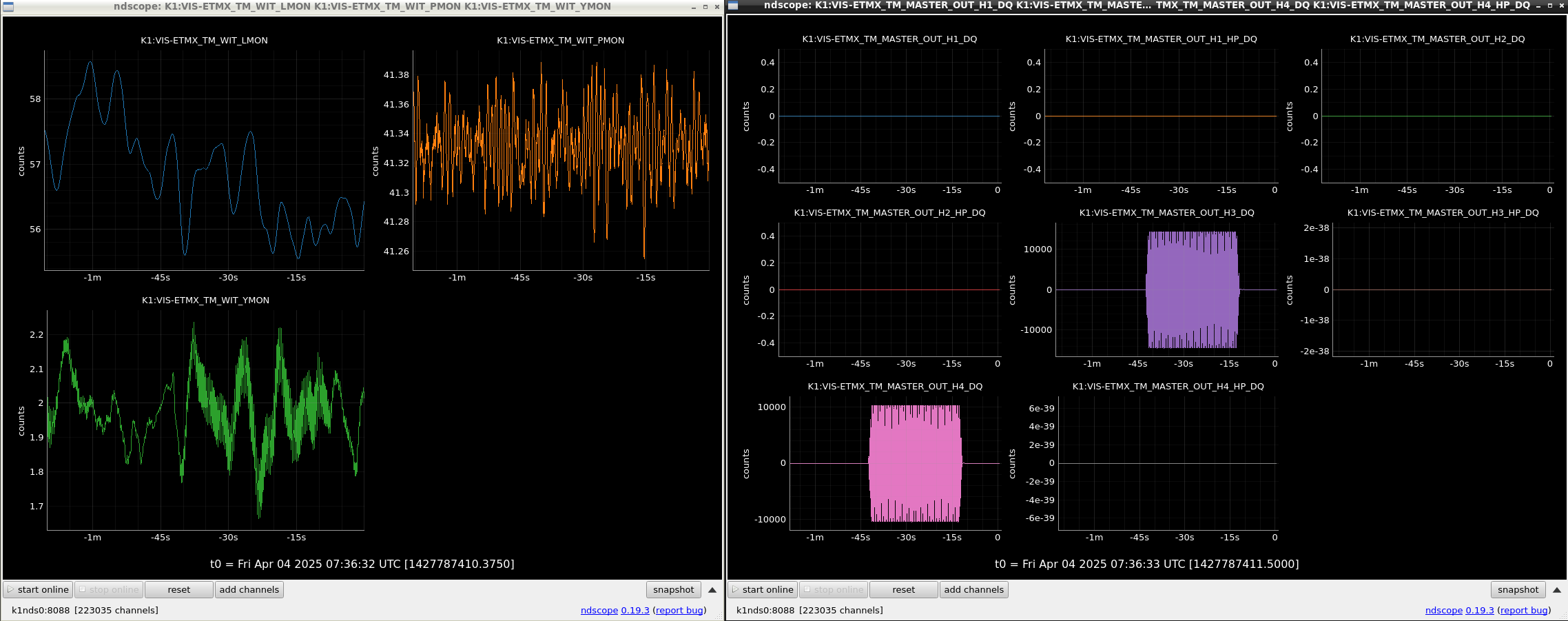
After the installation, we requested LOCK_ACQUISITION for VIS_ETMX guardian and it works well. Because there is no DAC output for TM stages in this state, I ensured that HPCD path is now enabled by using awg excitation. Figure 4 shows the TM Oplev signals with excitations from a HPCD path of the TM stage. For switching to a LPCD path and checking the injection via LPCD, we need to modify the real-time model. It will be done in next(?) maintenance day. Anyway, IFO lock with HPCD is probably now available.

Note
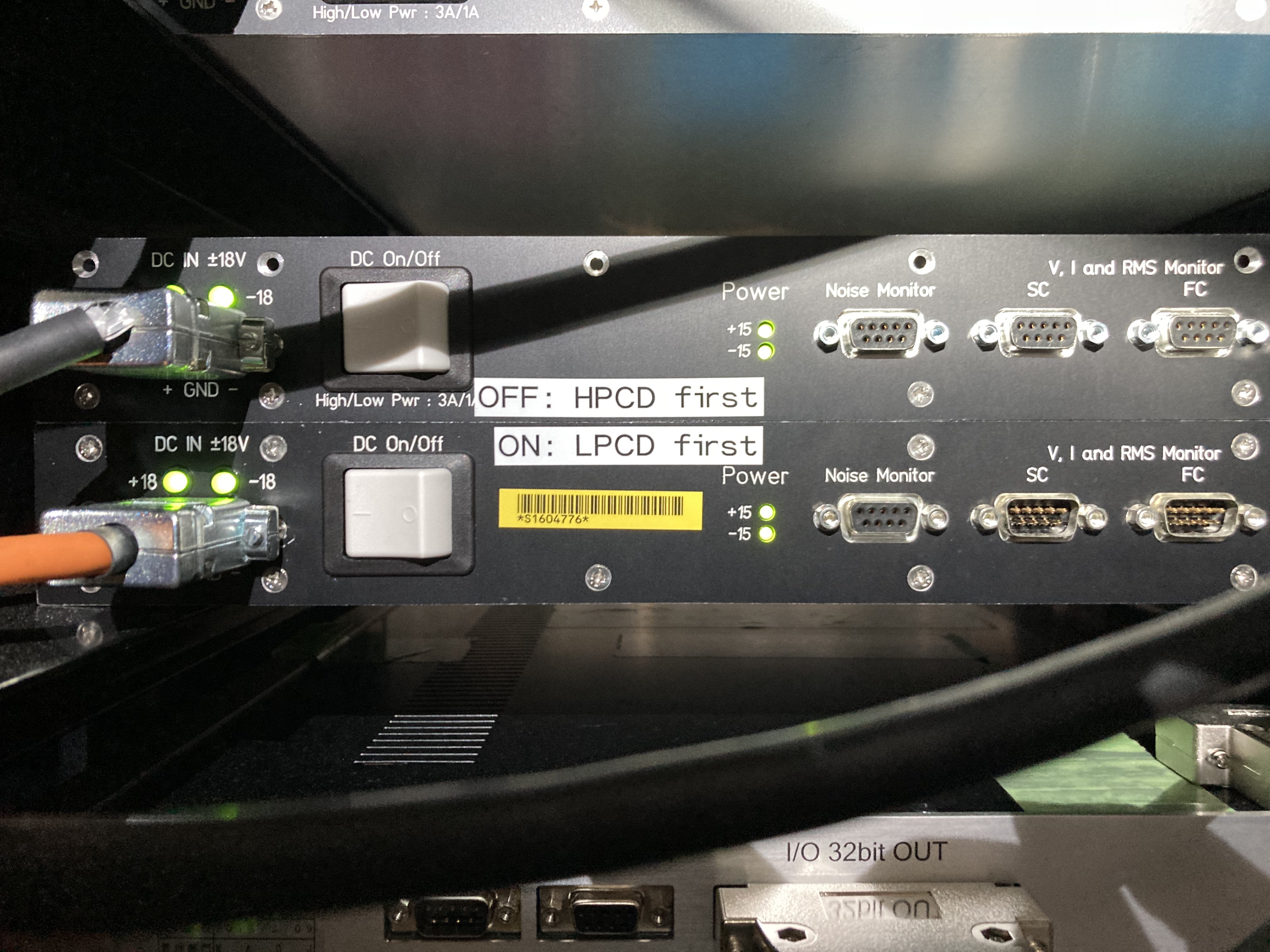
[1] DC power for the switcher board is derived from LPCD chassis. So we need to turn on LPCD before HPCD. On the contrary we need to turn off HPCD before LPCD. (see also Fig.5).
[2] A cable between the feedthrough and the coil driver output of IM blade damp is still left in EXV2 rack as shown in Fig. 6. If we don't need IM blade damp for future, they should be uninstalled.
[3] 'open' and 'close' of BIO are assigned for using HPCD and using LPCD, respectively in the current connection. In the case of Z-switch of OMC, 400Ohm (BIO 'close') has many peaks compared with 100Ohm (BIO 'open'). Though we haven't been sure the actual reason yet, BIO 'close' may induces undesirable noise due to additional connection to GND. If we will face many peaks when we swtich to LPCD, it may be better to try swapping the BIO assignement as 'open' for LPCD and 'close' for HPCD.

Images attached to this report
Comments to this report:
satoru.ikeda - 15:51 Friday 04 April 2025 (33247) Print this report

YamaT-san, DanChen-san, Ushiba-san, Ikeda

Overview

Work related to K-Log#33152 : Installation of Coil Driver Switcher

The model of k1ex1 was modefied for BIO connection of Low Power Coil Driver.
YamaT-san and others reported that they could not recognize all cards when the sixth DIO6464 card was inserted, so the existing BIO connection was changed.

Details of the change

BIO connection changes
 Before change
  k1visetmxlsc
   IMB: H32_C3
   TP: L32_C4
  k1visetmxt
   PI: L32_C0

 After change
  k1visetmxlsc
   IMB: remove
   TP (LPCD): H32_C3 (Moved from IMB) <- Reuse the entire coil driver from IMB, so use the wiring as IMB
   CoilDriver_SW: L32_C0 (Move from PI)
   TM_HP: L32_C4 (Move from TP)
  k1visetmxt
    PI: H32_C4 (BO: BO side of Release_Sensor is unused, so use this, BI:remove)

Model change point
PAYLOAD_MASTER/
  Add the following new block
 CRYO_PAYLOAD_16K_HP_MASTER
  Copy from CRYO_PAYLOAD_16K_MASTER and change BIO,TM block
  PAYLOAD_OPLEV_HP_TYPE_A_16K
    Copy from PAYLOAD_OPLEV_TYPE_A_16K and change MASTER, add COILOUTF_HP
  PAYLOADMASTER_HP
  PAYLOADBIO_HP
  A_PAYLOADBIO_HP_ENCODE  
  A_PAYLOADBIO_HP_DECODE
   Copy the original and add HP-related

 CRYO_PAYLOAD_16K_HP_MASTER
  Replaced with new block

k1visetmxt:
  Only change BIO connection

k1visetmxlsc: 
  Changed from CRYO_PAYLOAD_16K_MASTER to CRYO_PAYLOAD_16K_HP_MASTER
  Change of BIO connection
  DAC_1 In12-15: Change from TM_{H1,H2,H3,H4} to TM_{H1,H2,H3,H4}_HP
  DAC_2 In12-15: Change from GND to TM_{H1,H2,H3,H4}
  ETMX block changed from CRYO_PAYLOAD_16K_MASTER to CRYO_PAYLOAD_16K_HP_MASTER

SDF overwrote the EPICS value of TM_COILOUTF to safe.snap after renaming from TM_COILOUTF to TM_COILOUTF_HP.
Filter banks were copied from TM_COILOUTF to TM_COILOUTF_HP.
 

Images attached to this comment
Non-image files attached to this comment
takahiro.yamamoto - 19:32 Friday 04 April 2025 (33253) Print this report
[Dan, YamaT]

Abstract

We took back the BIO cables (CB{I,O}_L32_C1) for the BFV coil driver from the coil driver switcher,
and stole again the BIO cables (CB{I,O}_L32_C0) for the coil driver switcher from the PI coil driver.
After then, only one BO cable (CBO_H32_C1) is unused, so it connected to the CTRL port of the PI coil driver.
As a result, there is no readback of de-whitening filters for PI though it can be switched.
After our work, we engaged two stages of de-whitening filters for PI with confirming it by a sounds of relay switch.
 

Details

In the previous work klog#33152, we stole the BIO cables (CB{I,O}_L32_C1) for the coil driver switcher from the BFV coil driver. After then, Kenta and Ushiba-kun found the DAC noise contamination of GAS and BF stages (klog#33197). At that time they couldn't enable de-whitening filters for BFV because of the stolen BIO cables. As the temporal solution for this issue, Ushiba-kun inserted a config board for the BFV coil driver (klog#33223). In order to remove this temporal solution, we rewired the BIO cables.

Trying installation of a new BIO cards
At first, we tried to install a new BIO card as the 6th one on the IO chassis in the K1EX1 rack. But real-time front-end couldn't find any PCIe cards on the IO chassis when the 6th BIO cards were installed. According to my experience in the test stand, we was able to use 6 or 7 BIO cards on one IO chassis. Ambiguity of a number of cards seemed to come from an used cable between real-time front-end and IO chassis, the power supply situation, etc.

Though I'm not sure an exact reason why we reached a limit of a number of BIO cards as only 5, I guessed that it's also related to the total number of cards including also ADC, DAC, and BO. I was able to use 6 or 7 BIO cards with 1 ADC and 1DAC cards on the test stand. On the other hand, 3 ADC, 3 DAC, and 1 BO cards are installed on K1EX1. Anyway, we couldn't find a way to use the 6th BIO cards on K1EX1 though we tried to reboot some times and to use another PCIe slots.

Rewiring BIO cables
Because we found that it was impossible to use the 6th BIO card, we changed our strategy to the next best way as that BIO cables for the coil driver switcher is stolen from the PI coil driver instead of the BFV coil driver (DAC noise contamination from PI should be a smaller impact than one from BFV). So we removed the config board on BFV coil driver added by Ushiba-kun and took back the BIO cables from the coil driver switcher to BFV coil driver. Then we stole BIO cables again from PI coil driver in order to use on the coil driver switcher.

After rewiring, we found only one BO cable which was not used. A paired BI cable with this unused BO cable is apparently used for release sensors and the release sensors has only monitor channels. So we used this BO cable for PI coil driver for a control of de-whitening filters. Because there is no enough BI cables for PI coil driver, we cannot check the readback signal to ensure the state of filter engagement. So we confirmed to engage two stages of de-whiteninig filters by hearing a sound by relay switch. In common case, a state of the de-whitening filters for PI is never touched. So it might be enough to use a config board. If we obtained a benefit of using BO even an absence of BI, it's a time when we need to do a health check for ETMX. It's difficult to do the health check with enabling de-whitening filters because of DAC saturation.

Operation check
After the installation, we confirmed that de-whitening filter for all stages can be switched one-by-one and the test mass can be driven with LPCD. Fig.1 and Fig.2 shows the TM oplev signals when excitation was enabled from HPCD path and LPCD path, respectively. (I manually stopped two ndscope window for oplev signal and DAC output, so time epoch of two window has slightly a bias. Sorry for the lack of clarity.) We can see some excess on the oplev signals, so the coil driver output seemed to work fine. After then, we requested ALS_DARM and confirmed that changes in this work don't affect the lock acquisition.
Images attached to this comment
shinji.miyoki - 6:01 Tuesday 08 April 2025 (33294) Print this report

By the way, did you add and turn on several circuits in the EXV area? If so, the temp increase by ~ 0.6 °C can be explained. Anyway, Takahashi-san performed the off load for F0 and F1 because it drifted a lot. 

At present, no "small" cooler in the EXV area for the temp compensation.

Search Help
×

Warning

×