Abstract
I prepared a test environment for the Coil Driver Switcher board JGW-D2516468 on the Mozumi standalone system.
The intended functions, including the mechanism to prevent back EMFs in the coil, appears to be working well.
Glitch situation in switching coil driver, and the cross talk between HPCD and LPCD path were also checked today.
Though there is no loud glitches in switching coil driver, a difference in DC level (~10ct on ADC@STDA which seems to depends on channels) between two coil drivers can be seen.
Before installing, situation on actual channels used in the mine should be checked.
No crosstalk has been seen so far, but I just checked spectrum with sine excitation.
I will do a coherence check with longer integration time tomorrow.
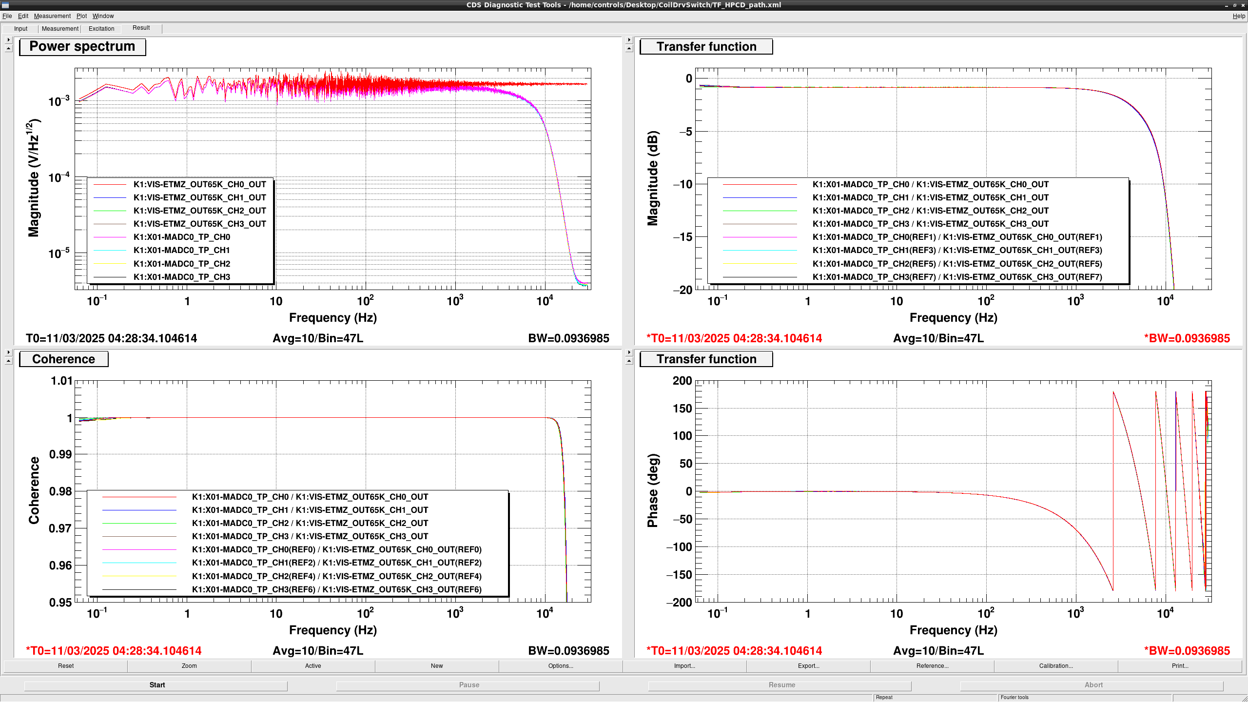
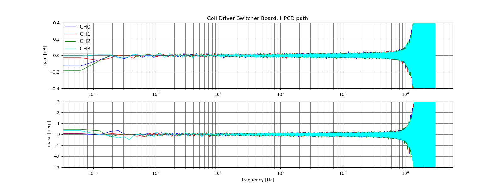
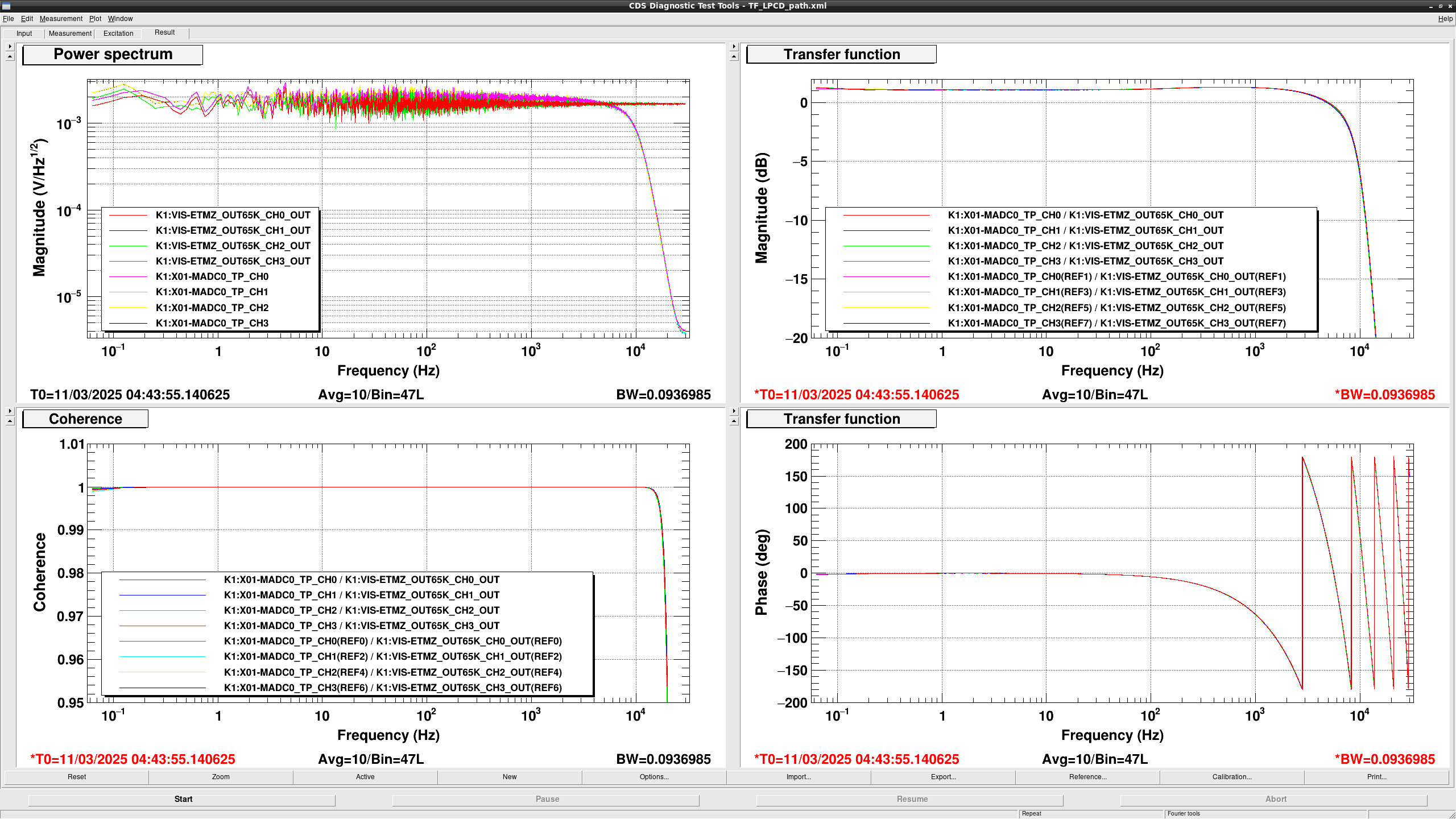
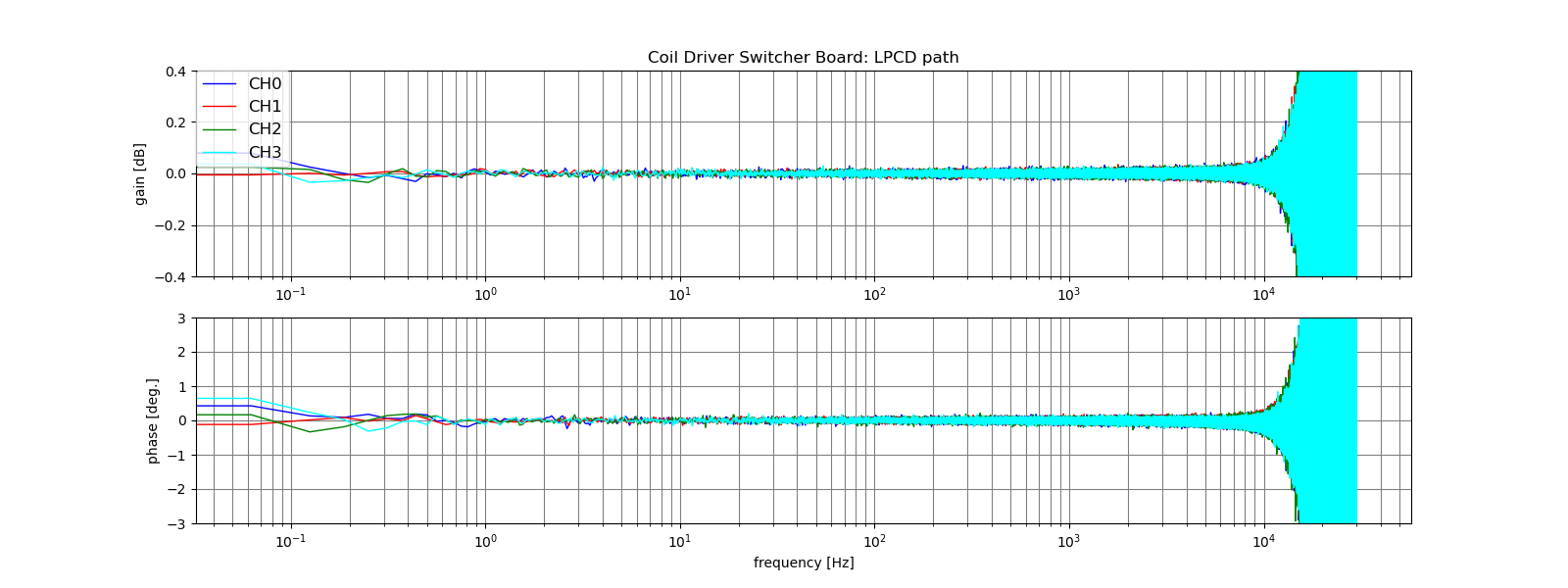
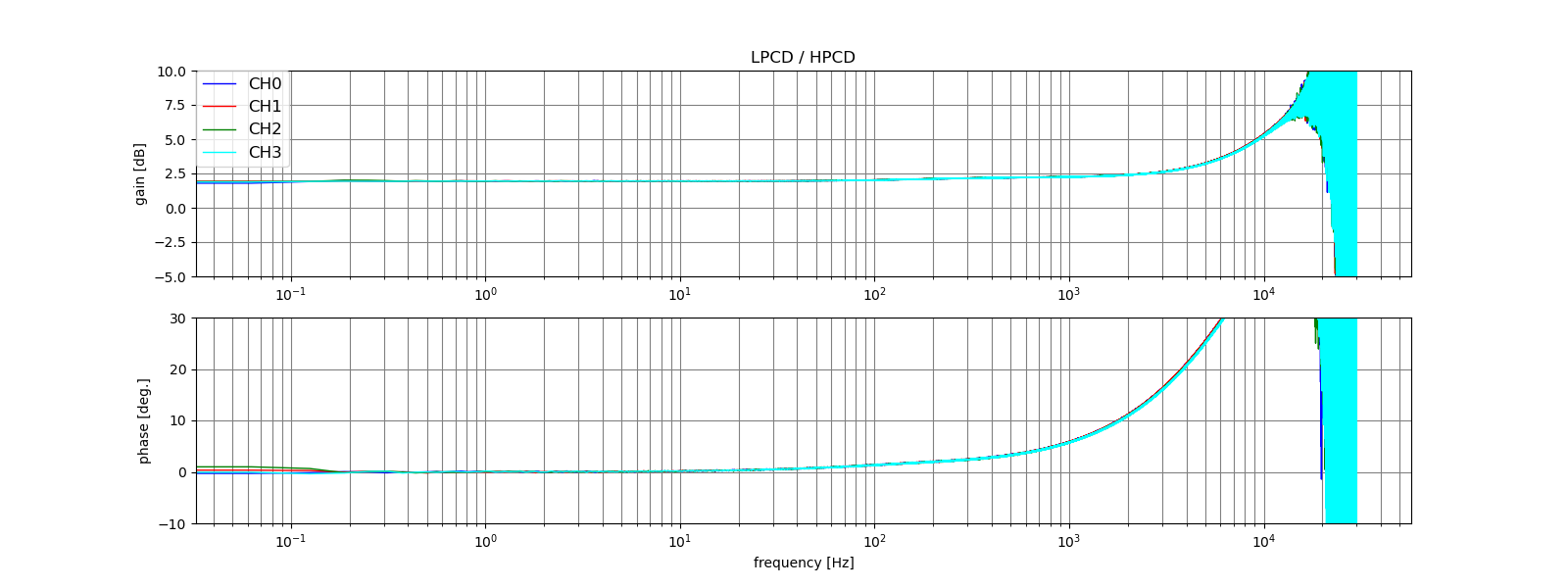
Remaining task is measuring transfer function of this board.
If a gain is not unity or there is an unintended delay, it will affect the calibration, so this should be checked before installation.
(After installation, we will also need to measure the gain in CAL week.)
Details
Model implementation
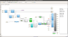
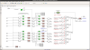
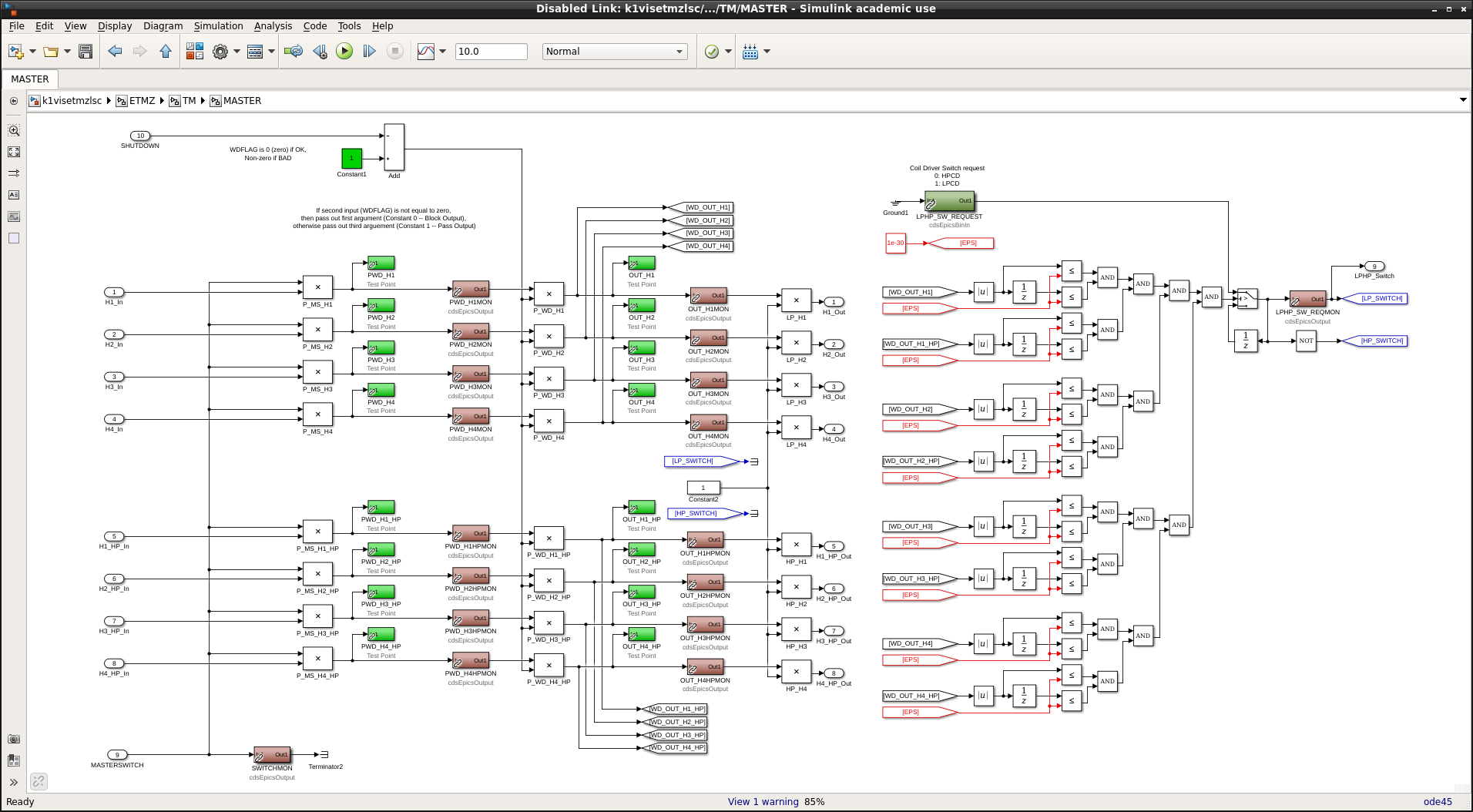
I imported the Type-A payload model to the standalone system to test the Coil Driver switching board and duplicated test mass output for LPCD and HPCD as shown in Fig.1. In the lock acquisition, switching coil drivers will be done on ETMX during the IFO lock by using TM stage of ETMY. So it'll be done without the DAC output for TM stage of ETMX. But if they are switched with large output by some kind of mistake, LPCD might be damaged by back EMFs. So I added new function in the DAC output to ensure the zero output from DAC for both LPCD and HPCD when we switch coil drivers as shown in Fig.2 (The right half is its function). In the operational phase, I'm planning that the DAC output connected to one coil driver will be turned off when the other coil driver will be used, but for now, both outputs are intentionally enabled at all times to check for cross-talk (see around center of Fig.2).
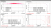
Glitch check
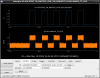
At first, I switched coil drivers by this board without any output from DAC of both LPCD and HPCD for checking the glitch situation. Figure 3 shows the BO output of switching request and coilout signal from switching board. Though there is no loud glitches, we can see some jump coming from a difference in DC level of two coil driver output. It's just ~10ct (from TM stage), so I think it's not so large to lose IFO lock (I want to know how much immediate change in offset on TM is acceptable). But it seems to depends on used channels, used coil driver chassis, and power source situation. So we need to know the these situation in the mine and we should avoid to use noisy DAC channels for these outputs.
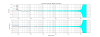
Check of safety mechanism
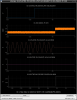
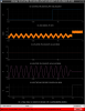
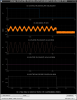
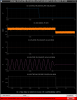
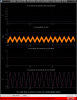
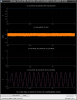
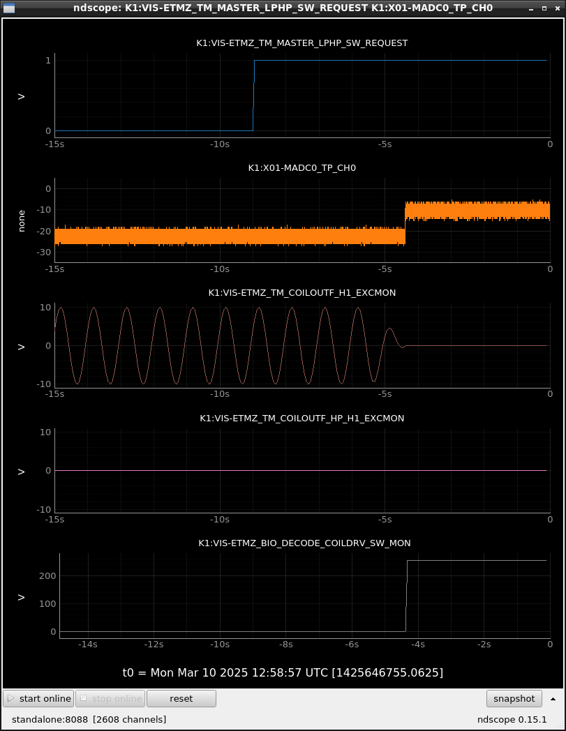
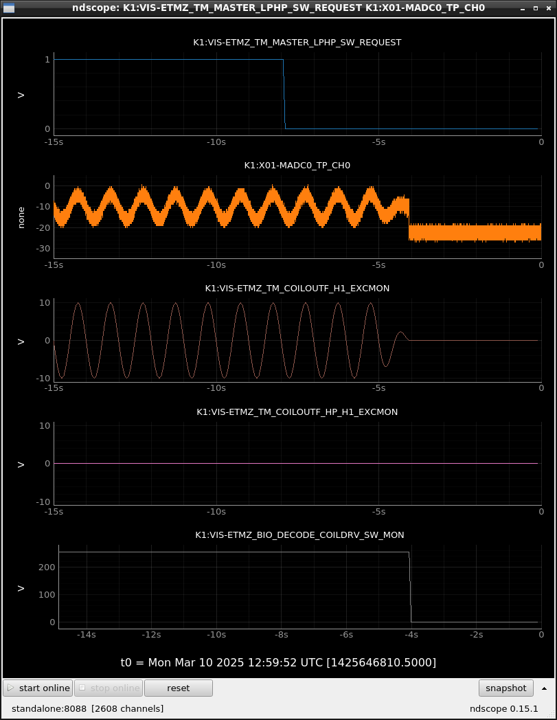
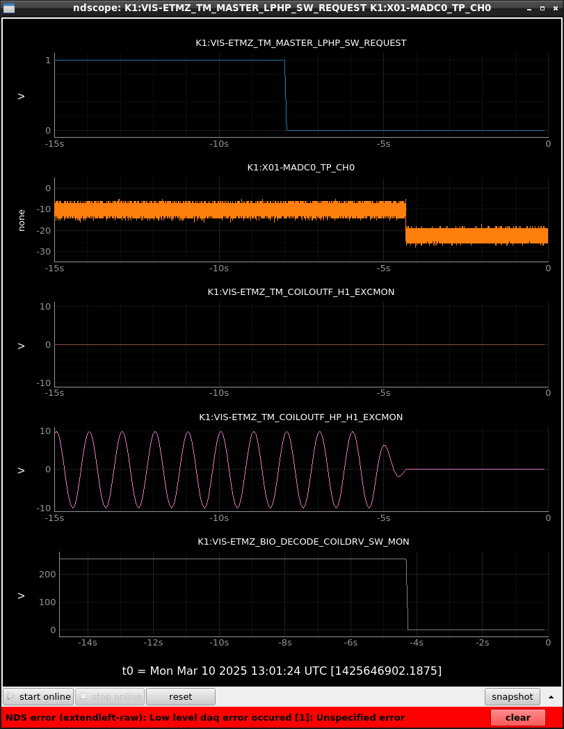
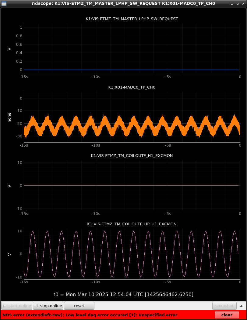
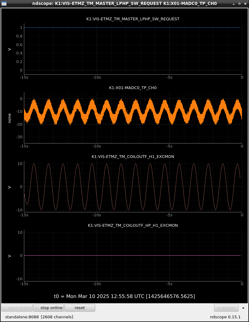
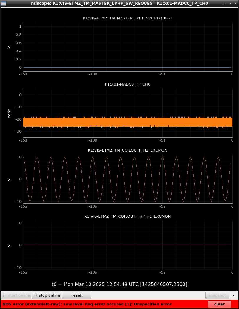
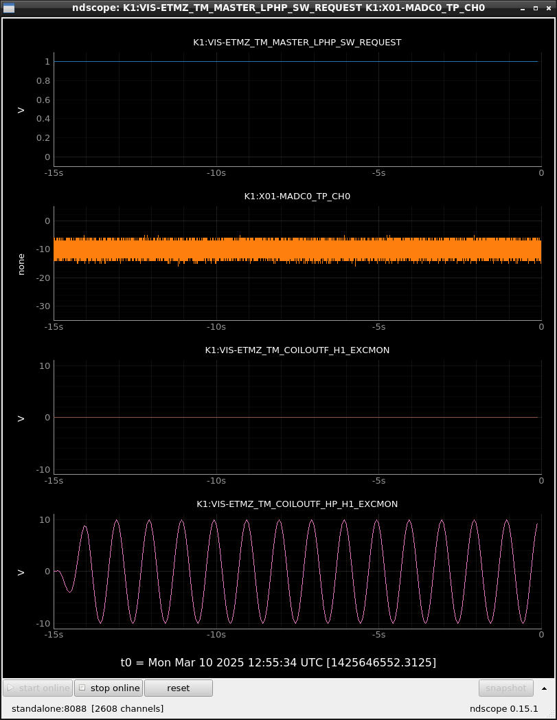
A new real-time model was made as switching coild driver can be done only when the coil outputs for both LPCD and HPCD are zero to avoid large back EMFs. So I switched coil drivers with some excitation to check that a new function to ensure the zero-outputs works fine. Fig.4-7 shows the switching request signal (top panel), coilout signals monitored on ADC (the 2nd top panel), excitation on LPCD path (the 3rd top panel), one on HPCD path (the 4th top panel) and the readback of switch state (bottom panel). Fig.4 and Fig.5 represent a case of switching from HPCD to LPCD with excitation from LPCD path and HPCD path, respectively. Fig.6 and Fig.7 represent a case of switching LPCD to HPCD. In all case, I disabled excitation a few seconds after changing request signal and the readback signal responded after disabling excitation. So safety function seems to work fine.
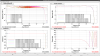
Cross-talk check
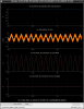
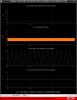
At first I check the cross-talk between the LPCD and HPCD paths with fewer excitation. Fig.8 and Fig.9 shows a case of enabling HPCD path with excitation from HPCD path and a case of enabling LPCD path with excitation from LPCD path. These are the check of signals from DAC on each path can be passed through when that path is enabled and seems fine (accurate gain and detailed check will be done in TF measurements tomorrow). Fig.10 (HPCD path is enabled) and Fig.11 (LPCD path is enabled) show the case of injecting signal opposite path which is enabled. In this case there is no injected signal on the coilout signal. So there seems to be no unintended direct connection.
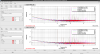
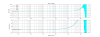
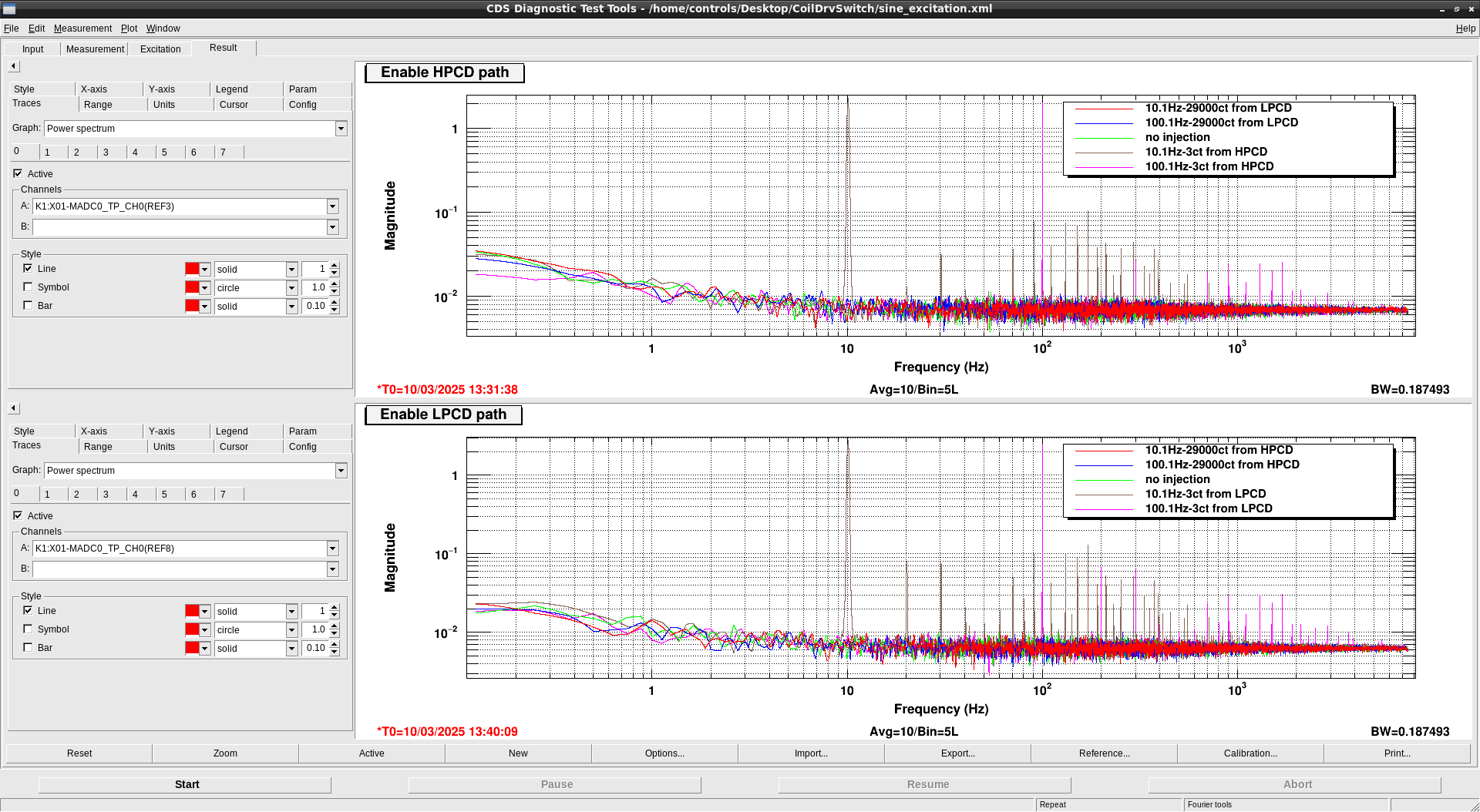
As the next, I checked cross-talk with larger excitation by checking ASD of coilout signal as shown in Fig.12. Even when we injected 29000ct at DAC (which is close to the limit of DAC rage) from opposite path, there is no signal on the coilout signal. In the actual operation, we are planning to the output from opposite path is disabled before DAC. So it should be no problem even if there is some small cross-talk. If more detailed check will be required, we can do it by using whitening filters for pick-up path of coilout signals and/or coherence check with longer time integration and so on.
