Consistent result with klog#31269 was available by my cross check.
So front-end calibration parameters were updated.
(After klog#31269, Ushiba-kun re-measure the OLTF but estimated optical gain is changed only ~0.3%.)
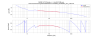
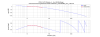
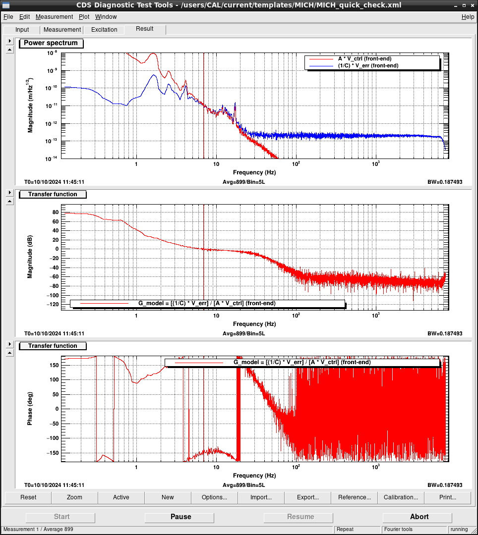
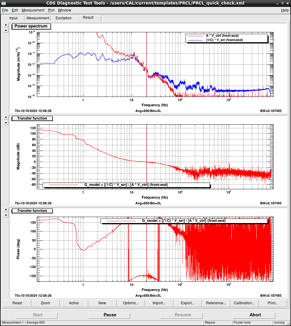
But computed OLTF as (1/C_model) * v_err / A_model * v_ctrl didn't become a smooth curve around UGF as shown in Fig.1.
This is typical behavior when calibration results are not so accurately.
I haven't found the reason yet (I gave up for today).
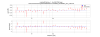
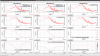
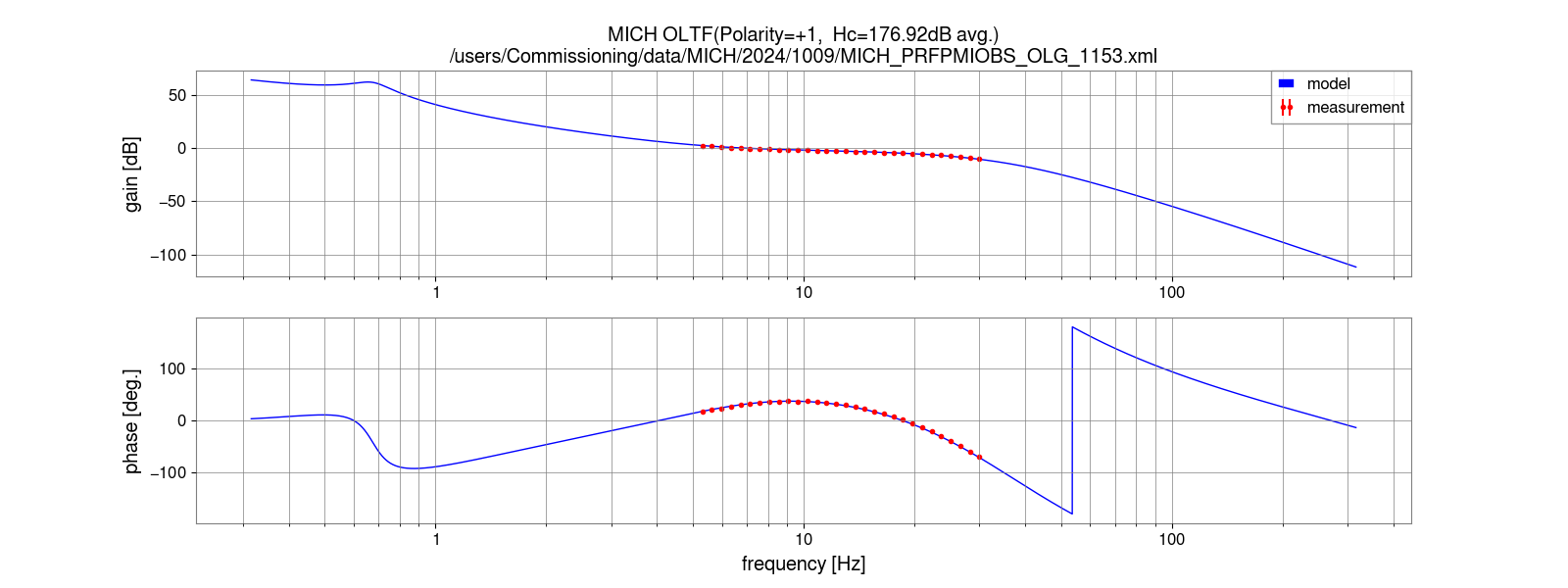
MICH and PRCL calibration were also updated with the actuator efficiency of BS (klog#29974),
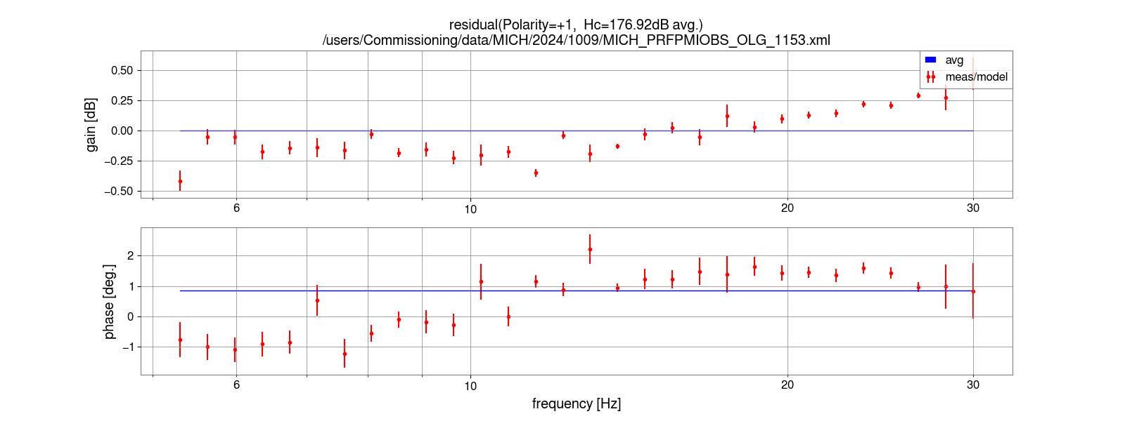
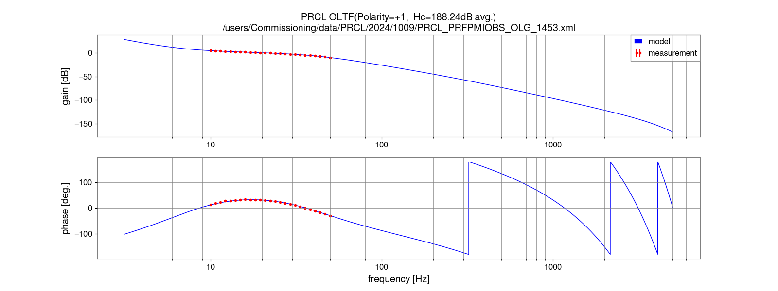
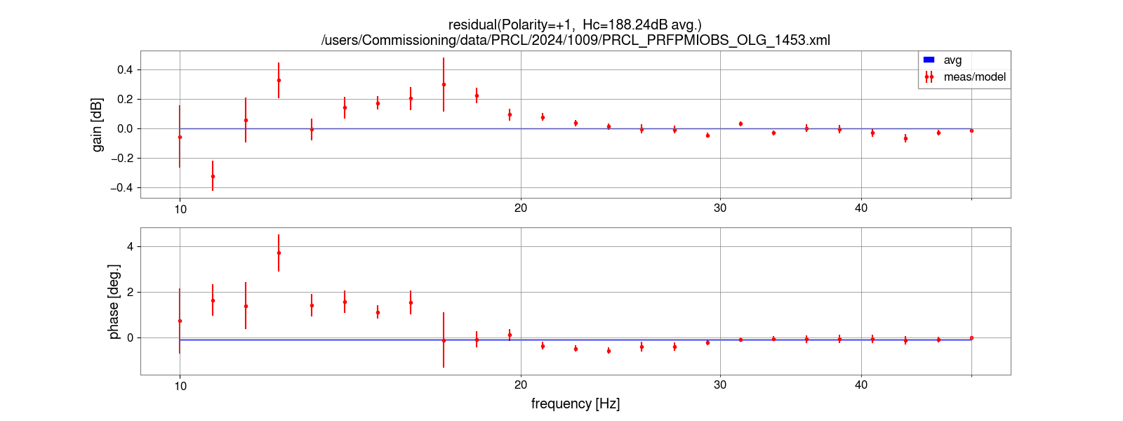
PRM (klog#30091 and the optical gain estimated from the OLTF measured in klog#31251 as shown in Fig.2-3.
They are also similar situation to DARM.
I'll do a more careful investigation in this weekend.
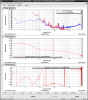
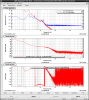

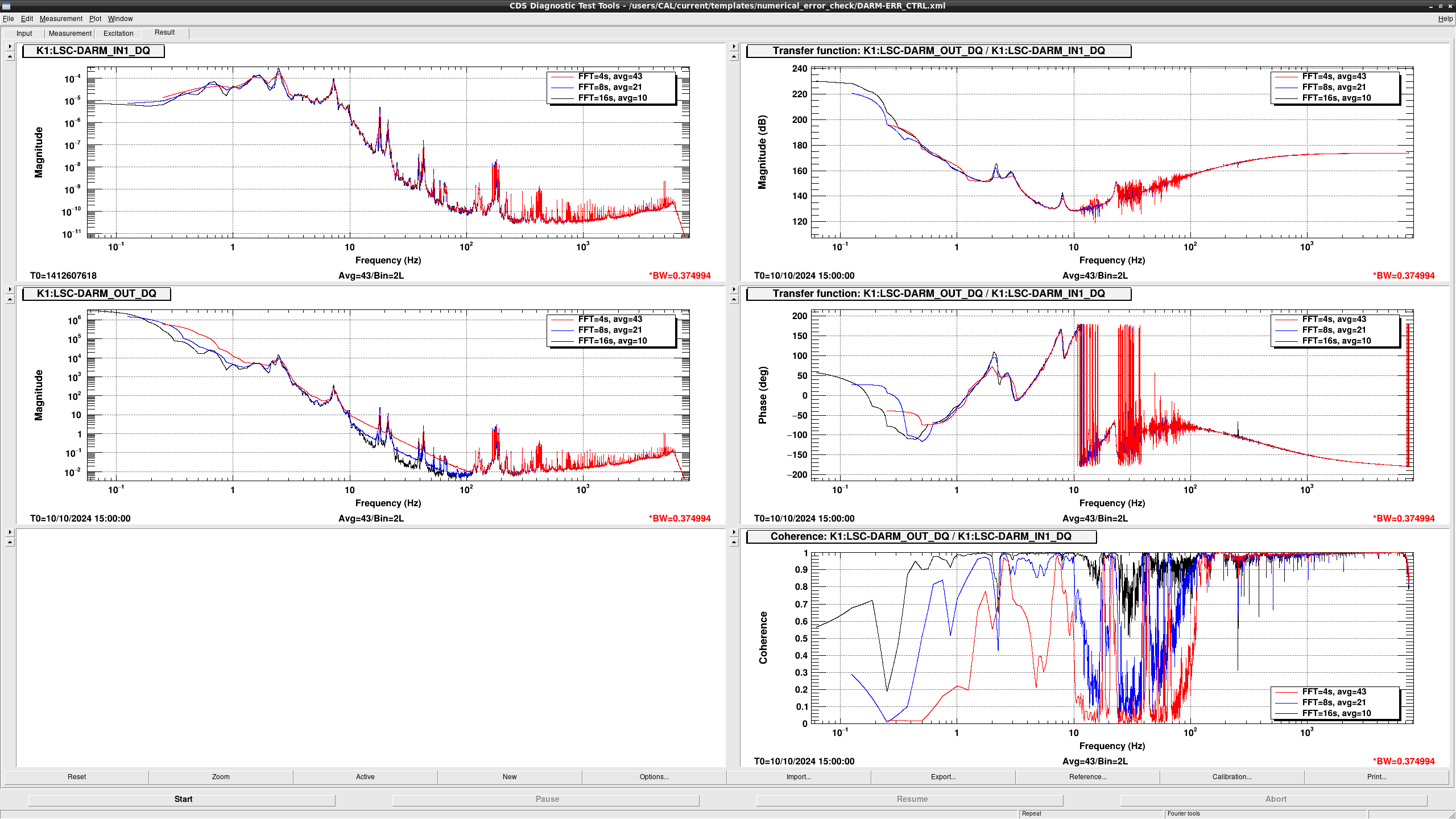
Figure 1 shows the spectra of raw error and feedback signals with the various FFT parameters. Data is chosen 88-second since 1412607618 (it's quiet data during last midnight).
With the shorter duration, spectrum of the feedback signal is contaminated.
Right panels show the transfer function and the coherence from the error signal to the feedback signal, which corresponds to the filters in DARM1 and DARM2. Because of the numerical errors, there is no coherence even the case between the error signal to the feedback signal. This fact means that the quick check by this way is no longer useful for the cross-check of the calibration.
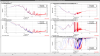
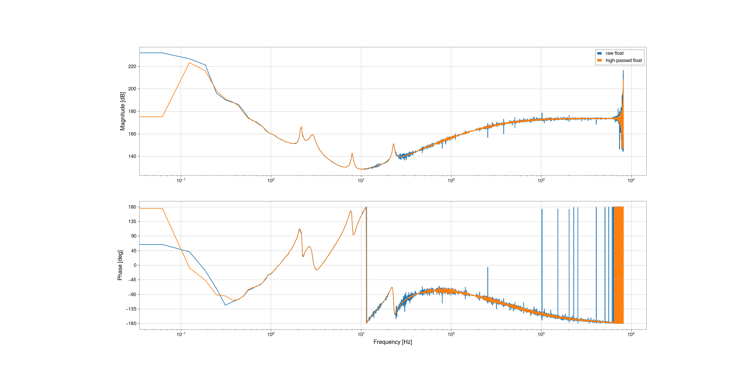
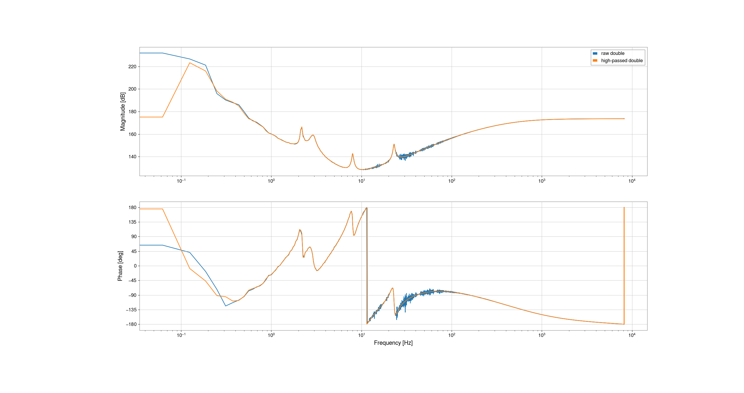
As an another check, I tried to compute the TF from the error signal to the feedback signal with the offline data. Figure 2 shows the TFs estimated with raw K1:LSC-DARM_{IN1,OUT}_DQ and with high-passed them. Thanks to the high-pass filter, numerical errors are mitigated but are not removed completely. This fact may mean time-series signal of the feedback signal in single floating is already contaminated. Figure 3 shows the same plot with signals saved in double floating. In this case, smooth curve is available by using high-pass filter. So the time-series signal in the double floating doesn't seem to be contaminated, but FFT process requires the high-pass filter.
Because signal processing in the real-time model is done with double floating, numerical errors doesn't seem to contaminate the real control signal. But we need to take care about this fact when we measure something with diaggui in which signal processing is done with single floating. (For the case of gwpy, we should use astype(np.float64) in order to cast saved data as single->double).
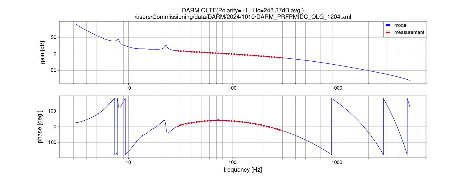
Though we need to consider how to do the cross-check, we concluded current calibration is correct within the difference between the measured OLTF and its model.
Each OLTF is shown in Fig.4-9.

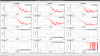
For the future analyses not only calibration but also other activities, I searched where the numerical contamination occurs by checking transfer functions between IN-OUT of each filterbank.
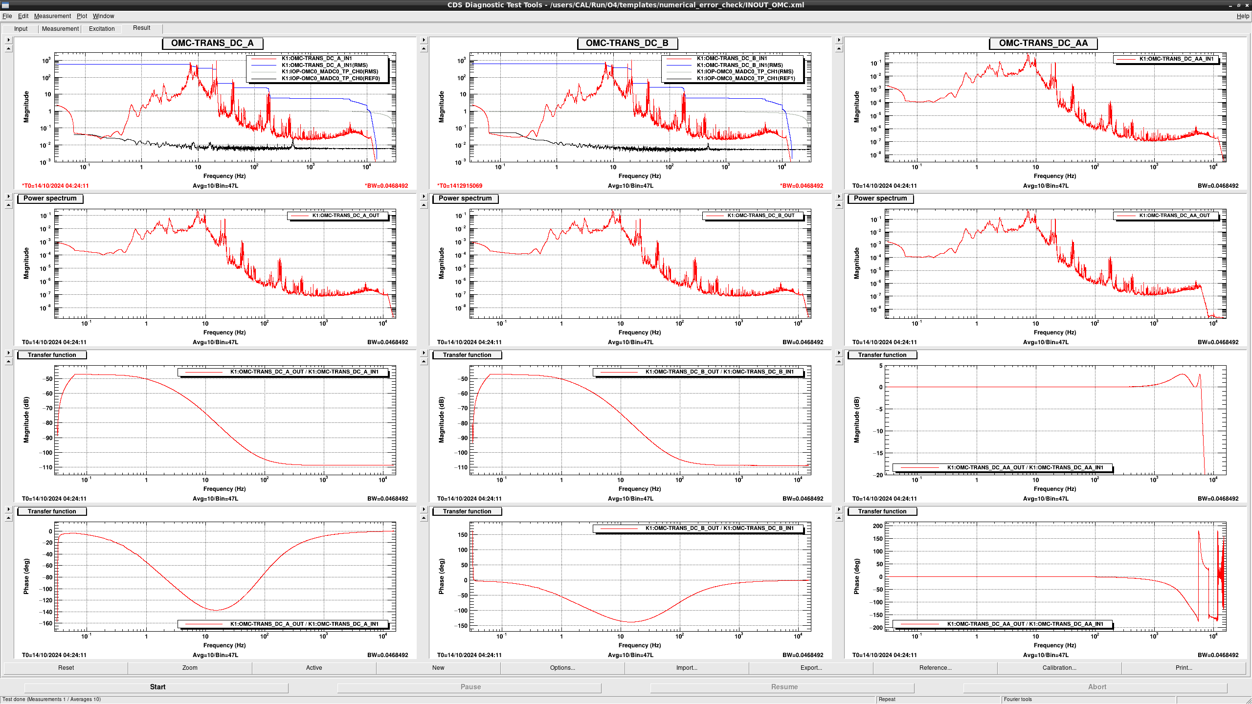
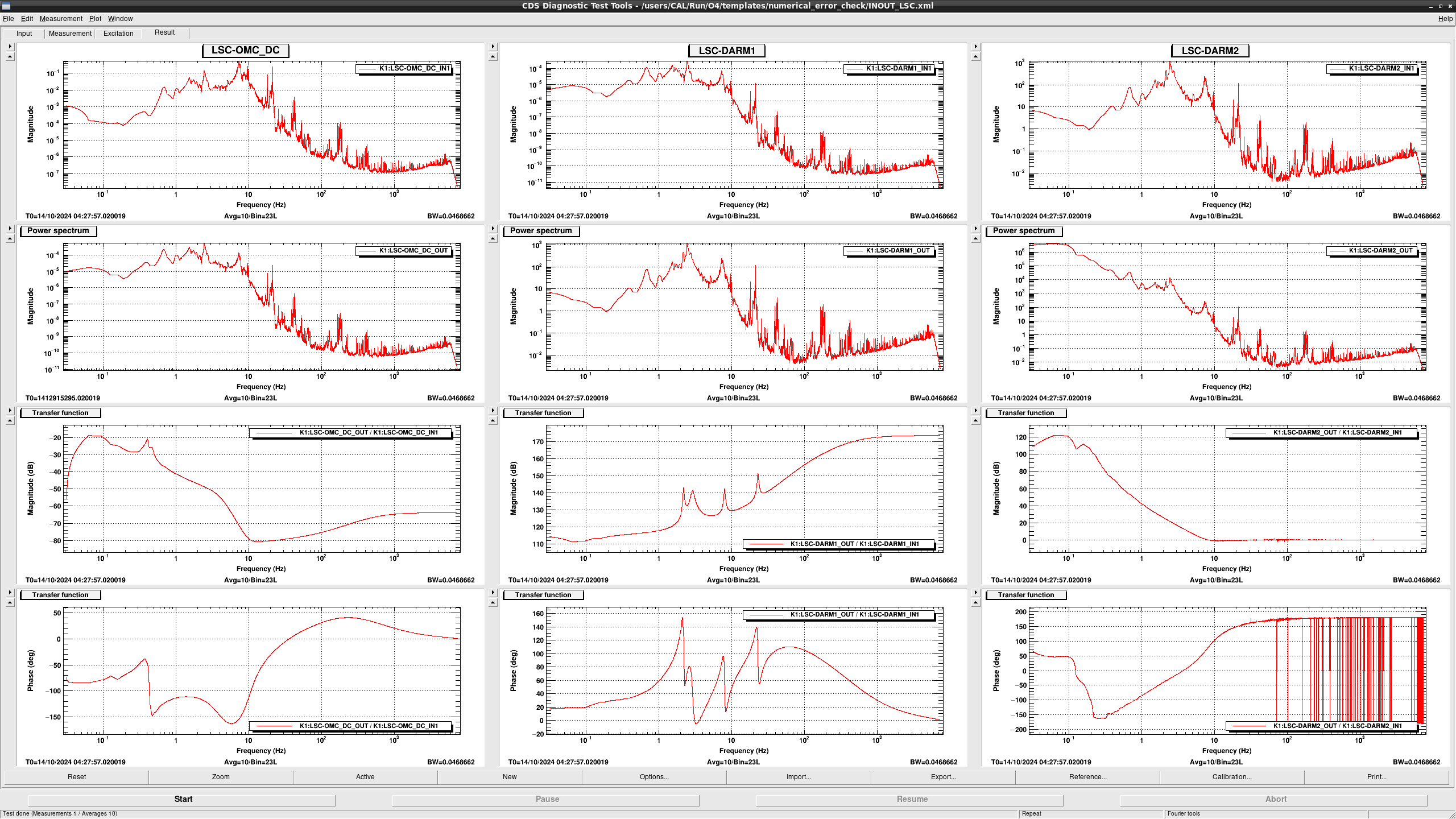
OMC related (Fig.1)
The left and middle columns in Fig.1 show the ASD of input/output signals and the transfer function from input to output of DCPD filter banks (OMC-TRANS_DC_{A,B}). Input signals are not contaminated by ADC noise and there is no problem on the ADC range. And also, we cannot see the contamination in the transfer function. So the output of DCPD filter banks should be also clean.
The right column in Fig.1 shows signals related to the Anti-aliasing filter bank (OMC-TRANS_DC_AA) for the down sampling between 32kHz OMC model and 16kHz LSC model. We cannot see the contamination also on this filter bank as expected.
We can conclude that signals on OMC models are not contaminated for now. (Though there is a filter bank named as OMC-TRANS_DC_SUM, it was not checked because the filter is not set on this filter bank.)
LSC related (Fig.2)
LSC related filter banks are LSC-OMC_DC, LSC-DARM1, and LSC-DARM2. Input of LSC-OMC_DC which is same as output of OMC_TRANS_DC_AA should not be contaminated. And also we can see smooth transfer function of LSC-OMC_DC and LSC-DARM1. This means that signals from LSC-OMC_DC_IN1 to LSC_DARM2_IN1 are not contaminated.
On the other hand, the transfer function of LSC-DARM2 shows strange structure around 100Hz. This structure seems to come from some kind of contamination.
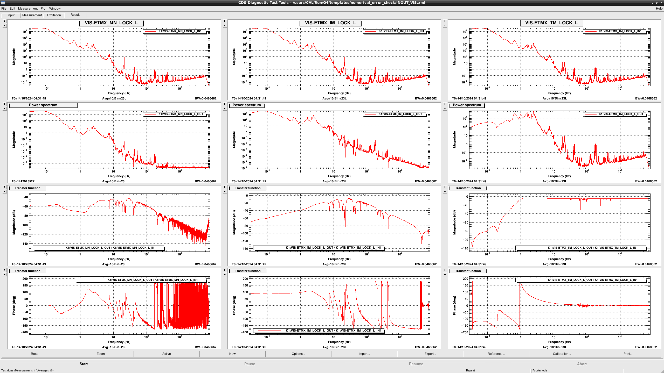
VIS related (Fig.3)
Because LOCK_L_IN1 is same as LSC-DARM2_OUT, measured transfer functions of {MN,IM,TM}_LOCK_L show the contamination around 100Hz. Contamination in such high frequency is not so serious problem for MN and IM but we should consider carefully for TM. (ISCINF_L was ignored because of no engaged filter module.)
For investigating the improvement by the Whitening-Dewhitening technique, I applied the whitening filter to the input of TM_LOCK_L. Because we cannot insert the whitening filter in real control path on TM_LOCK_L, I used unused filter bank on CAL model which was prepared for the h(t) reconstruction for the case ITMs are used for DARM control (CAL-CS_DARM_FE_ITM{X,Y}_TM_LOCK_L).
"gain" and "FILT_TM" filter modules on VIS-ETMX_TM_LOCK_L was copied to these CAL filter banks and 1 and 2 whitening filters (z10:p100) are added on CAL-CS_DARM_FE_ITMX_TM_LOCK_L and CAL-CS_DARM_FE_ITMY_TM_LOCK_L, respectively.
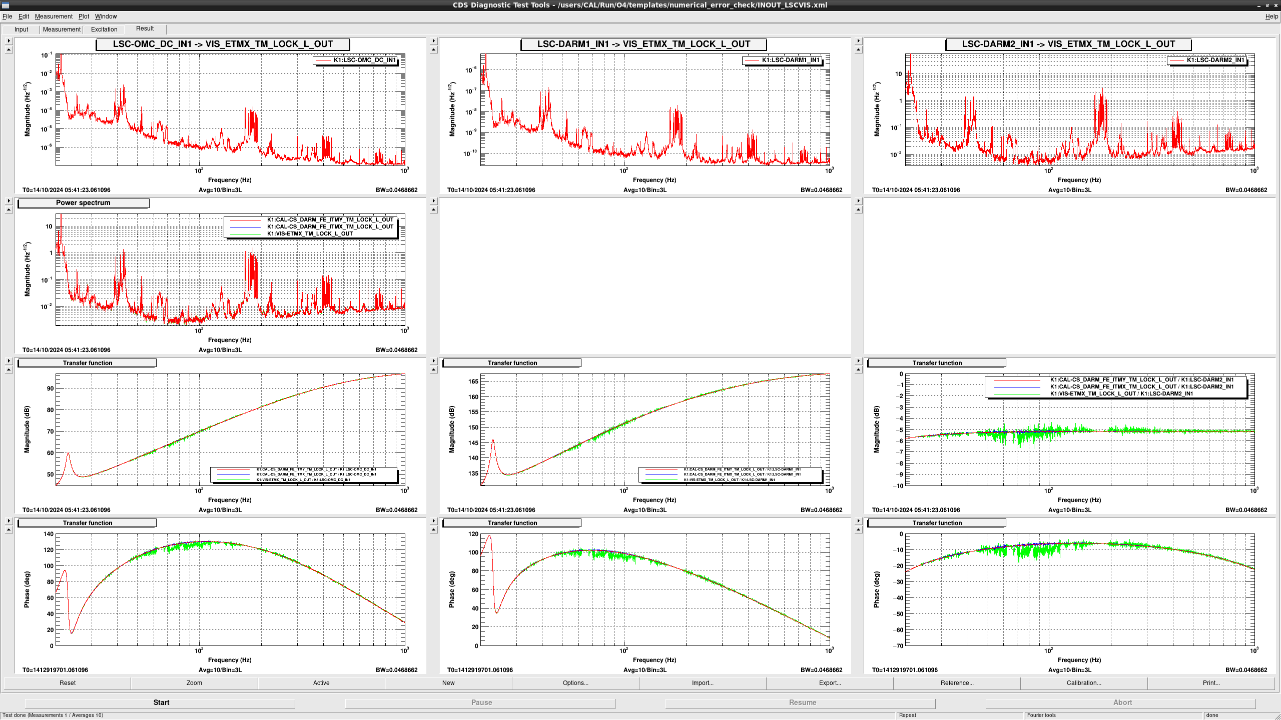
Transfer function from non-contaminated signals (LSC-OMC_DC_IN1, LSC_DARM1_IN1, and LSC_DARM2_IN1) to these TM_LOCK_Ls are shown in Fig.4. TF to VIS-ETMX_TM_LOCK_L_OUT (green curve) shows ugly contamination. But TF with 1 (blue curve: CAL-CS_DARM_FE_ITMX_...) and 2 (green curve: CAL-CS_DARM_FE_ITMY_...) whitening filters show the some improvement.
Conclusion
From these results, time series signals in the DARM loop are not contaminated. But we need some whitening filters for the various measurement (calibration, noise projection, etc.) with signals at the down stream of LSC-DARM2.
According to the previous post (klog#31290), applying to the whitening filters to the DAQ-ed time series signals as single float is not enough and applying them to double float is required. This means that we need additional filter banks to apply the whitening filter on the real-time model. (I plan to add some filter banks for the calibration measurements).
On the othre hand, if this issue becomes serious problem on other activities, we may need to re-design the DARM servo filters (LSC-OMC_DC, LSC-DARM1, LSC-DARM2, and VIS-ETMX_{MN,IM,TM}_LOCK_L) for reducing the dynamic range at the error and feedback points. (e.g. removing integrator in DARM2 and high-pass in TM_LOCK_L, and adding integrator in {MN,IM}_LOCK_L)
