Ushiba, Washimi, D. Chen, Miyoki, Akutsu (remote R. Takahashi, Aso)
Summary
This is a part of finalization procedure for IMC. We tuned EQ stops finely for MCi and MCo suspensions. The relevant works for MCe would be reported by Washimi separately.
Background
As reported in 28892 and following posts, newly designed and manufactured side EQ stops were installed for earthquake countermeasure. On the other hand, we were not confident wether the side EQ stops were properly installed or not; they have to stop large mirror motions before the magnets hit the coils at eathquakes. In fact, the photos in 28893 and 28894 might seemingly indicate some of the gaps between the magnets and the coils would be narrower than the gaps between the EQ stops and the mirrors. Due to inherent difficulties in the type-c suspensions, the suspended mirror might not come back to the original location each after clamping it with EQ stops, unfortunately. But it would be very hard to adjust the coil locations for a freely swinging mirror within realistic time schedule.
Preparation
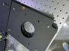
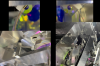
As a preparation, one of the shield plates of the MCi suspension structure (in the -X direction) was detached, and stocked in the IMC_REFL optical table (Fig. 1).
Inspection of gaps between magnets and coils
To know to what extent we have to bring the EQ stops close to the mirrors, we needed to know the coil-magnet gap sizes. If the coil-magnet gaps would be too narrow, the coil location should be manually adjusted, although it should be too risky.
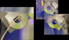
As a result of visual inspection, fortunately, we did not need to adjust the coil locations manually. It was very hard to visually inspect the coil-magnet gaps. We tried several ways for the visual inspection, and finally confirmed that the gaps would be sufficient, though there are some variations; the gaps are seeminlgy more than ~0.8 mm (of course we could not measure these numbers with rulers...). We fonud the best way for this visual inspection was to observe the coil-magnet from the AR side, but sometimes it was hard so basically looked at from the HR side. We found that 2D (usual) photos were not useful tool to record the real situation properly, while our eyes and brains seemingly reconstuct 3D information reasonablly.
Tuning the locations of the side EQ stops
Me and D. Chen adjusted the locations of the side (upper) EQ stops for MCi and MCo suspensions. The procedure was:
- Both of the side EQ stops were set back about 5 mm to increase the gaps between the EQ stops and the mirror. At least I could access and adjust these EQ stops with my fingers without feeling severe risks of touching the suspension wires.
- Loosen two screws with which a plate holding the above two EQ stops. We had to support this structure not to fall down on the mirror.
- Step by step, we lowered the plate and fixed it again at a proper height we thought.
- Then, adjusting the side EQ stops to narrow the gaps to the mirrors. Our goal was to narrower than the coil-magnet gaps, as much as possible, but should not make it too narrow. The balance should be taken.
Then we did health check of the suspensions (probably to be reported by Ushiba).
Inspection of gaps again
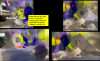
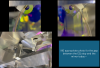
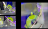
After the health check, and after checking IMC flash (28912), I and Ushiba redid visual inspection of the gaps. Maybe ok... Figs. 2 and 3 show the gaps for MCi, and Figs. 4 and 5 for MCo. In addtion to these side EQ stops, the front and back EQ stop gaps were also inspected by us.