Hirata, Dan, Ikeda, Komori, Aso
We brought this suspension to the following state:
- OpLevs are centered (both tilt and length)
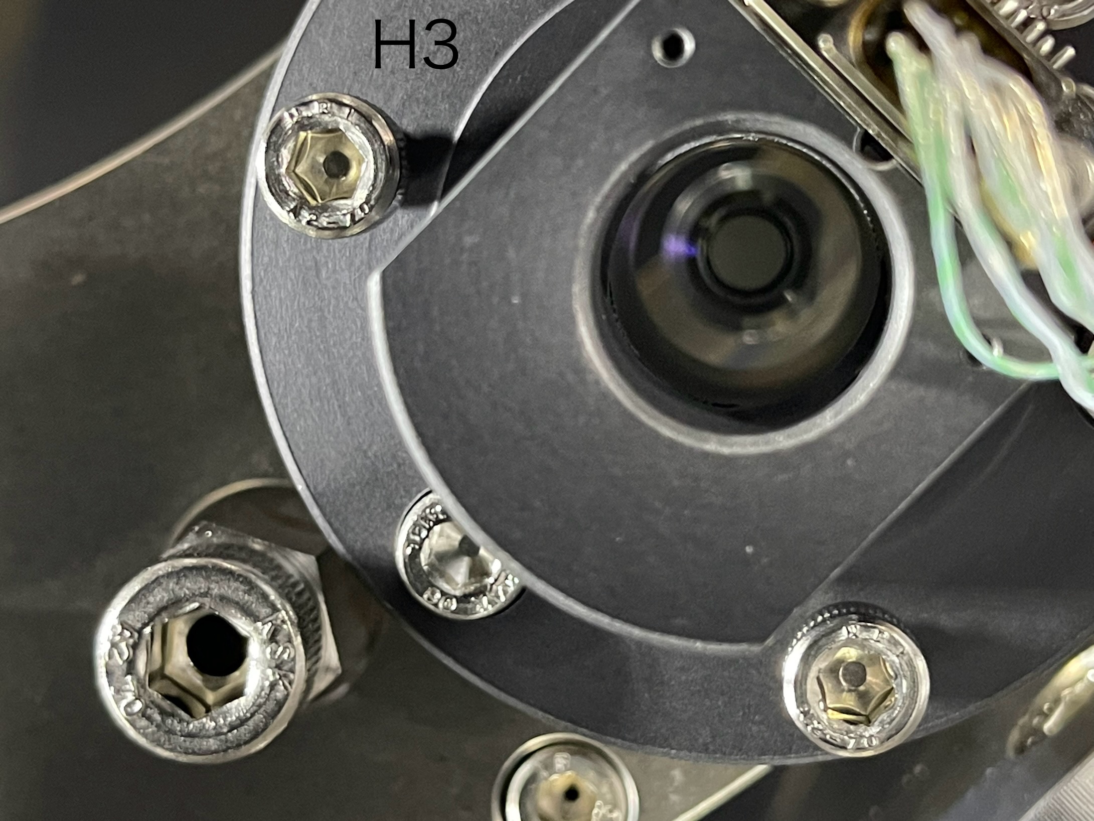
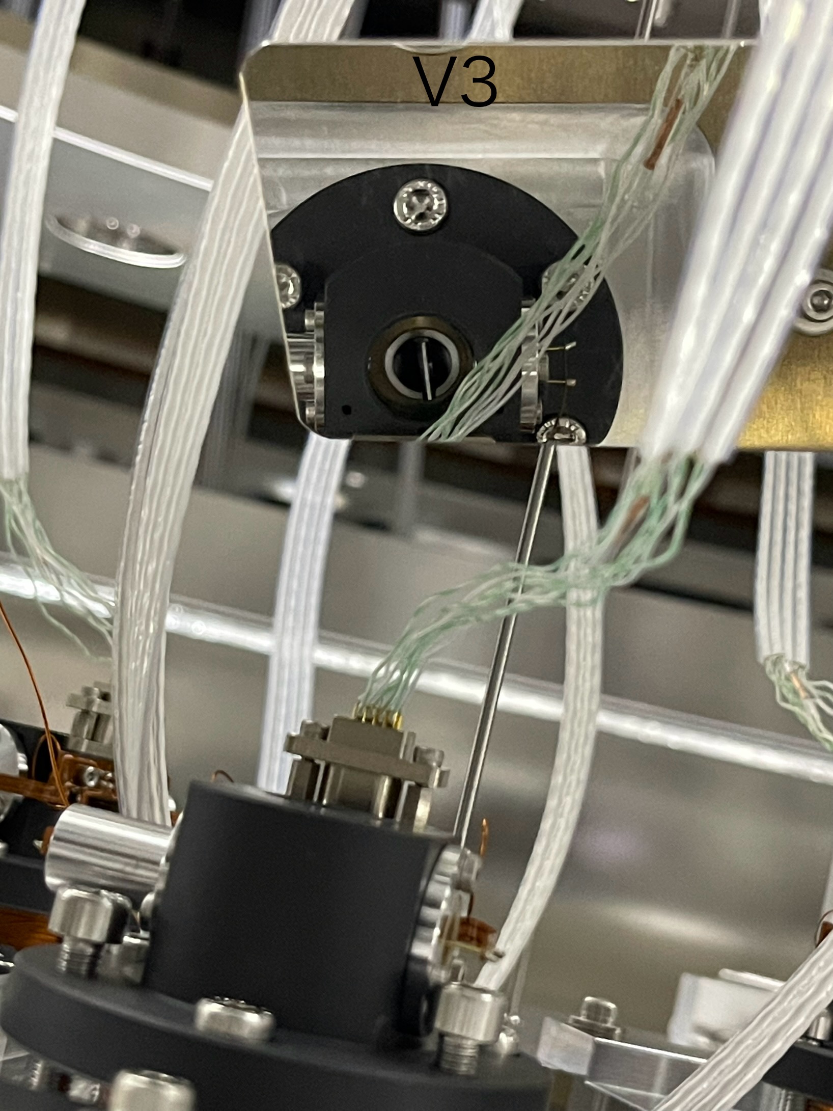
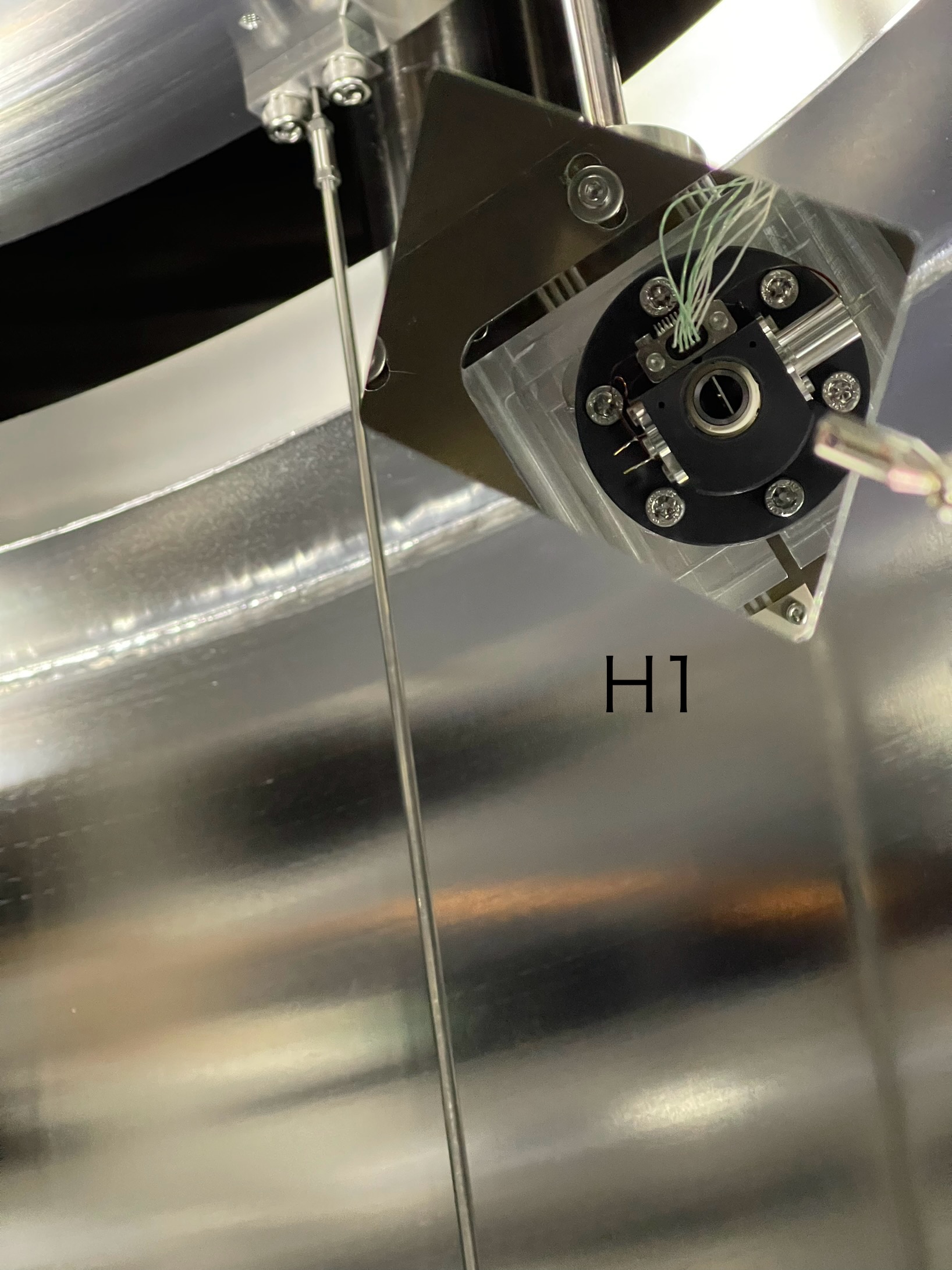
- All the OSEMs are in good range.
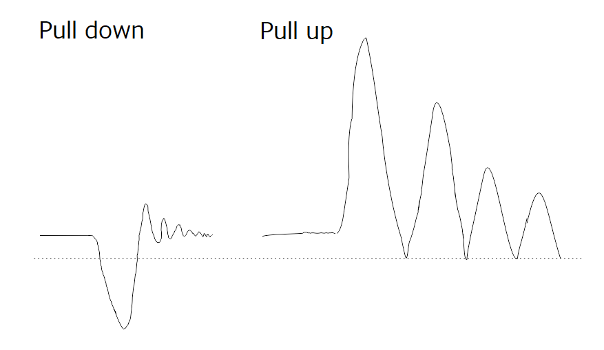
However, as reported by Ushiba-san, the TFs are strage. So we need to find what is rubbing.
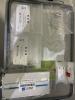
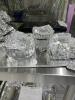
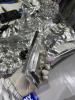
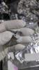
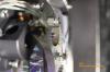
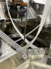
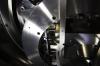
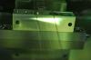
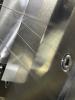
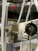
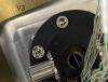
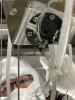
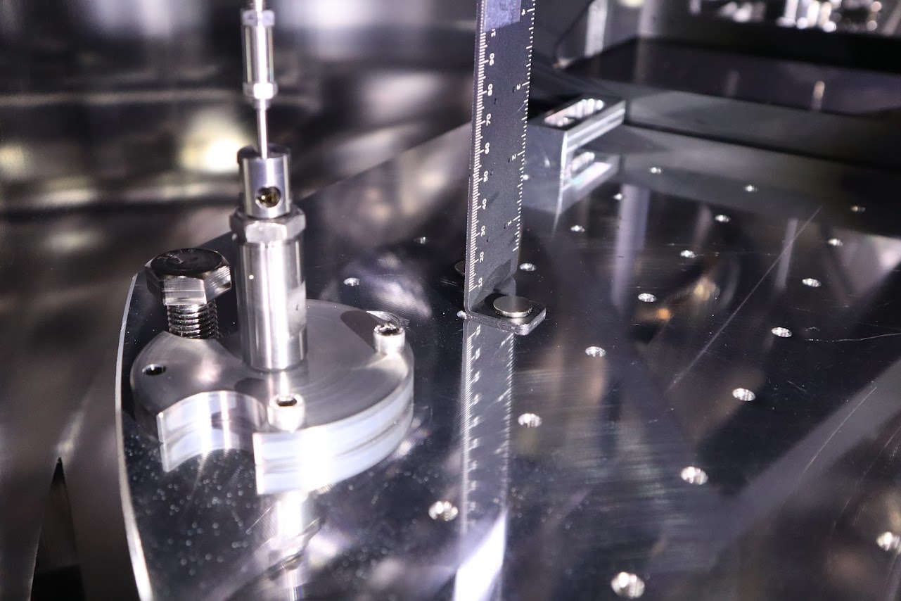
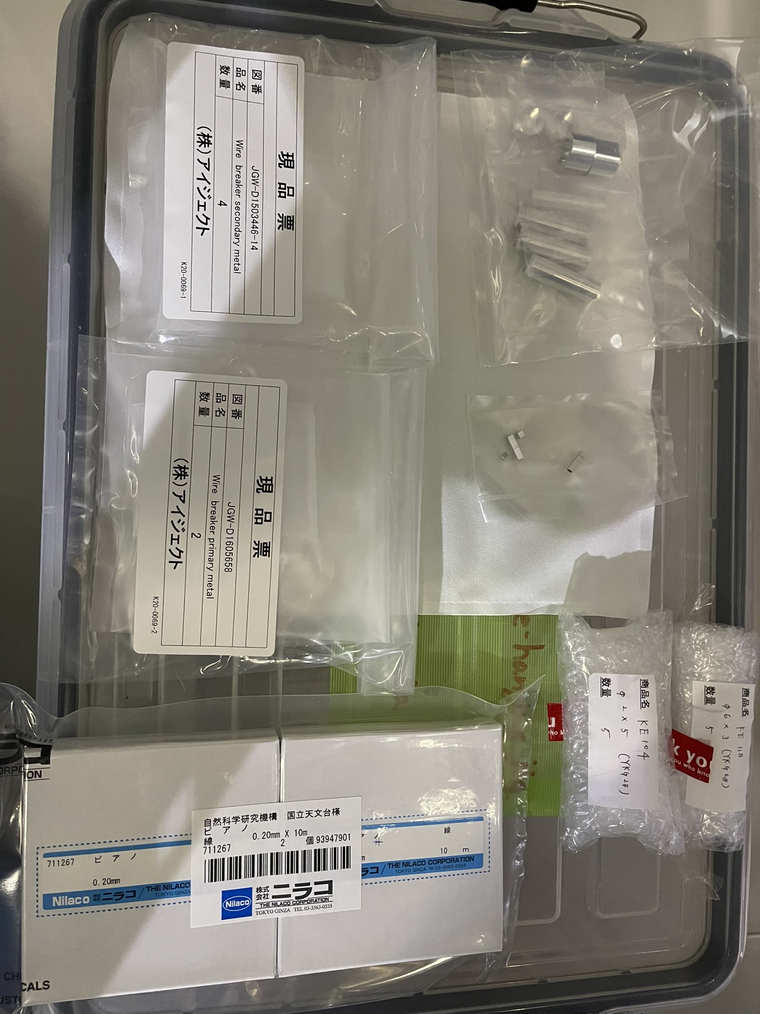
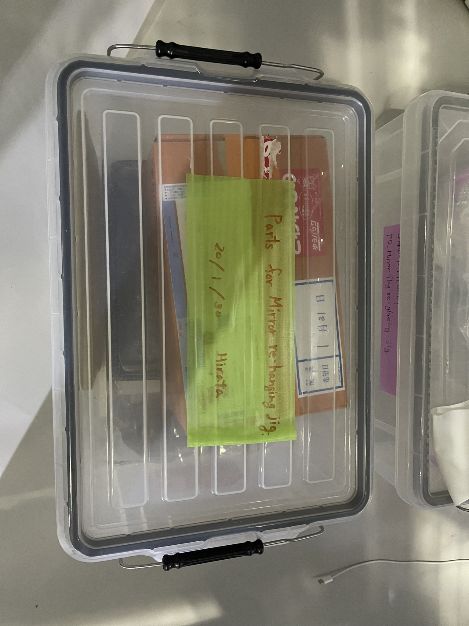
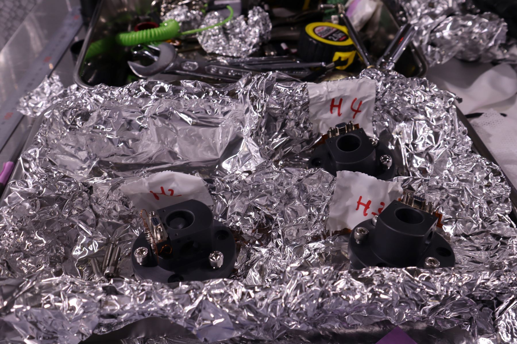
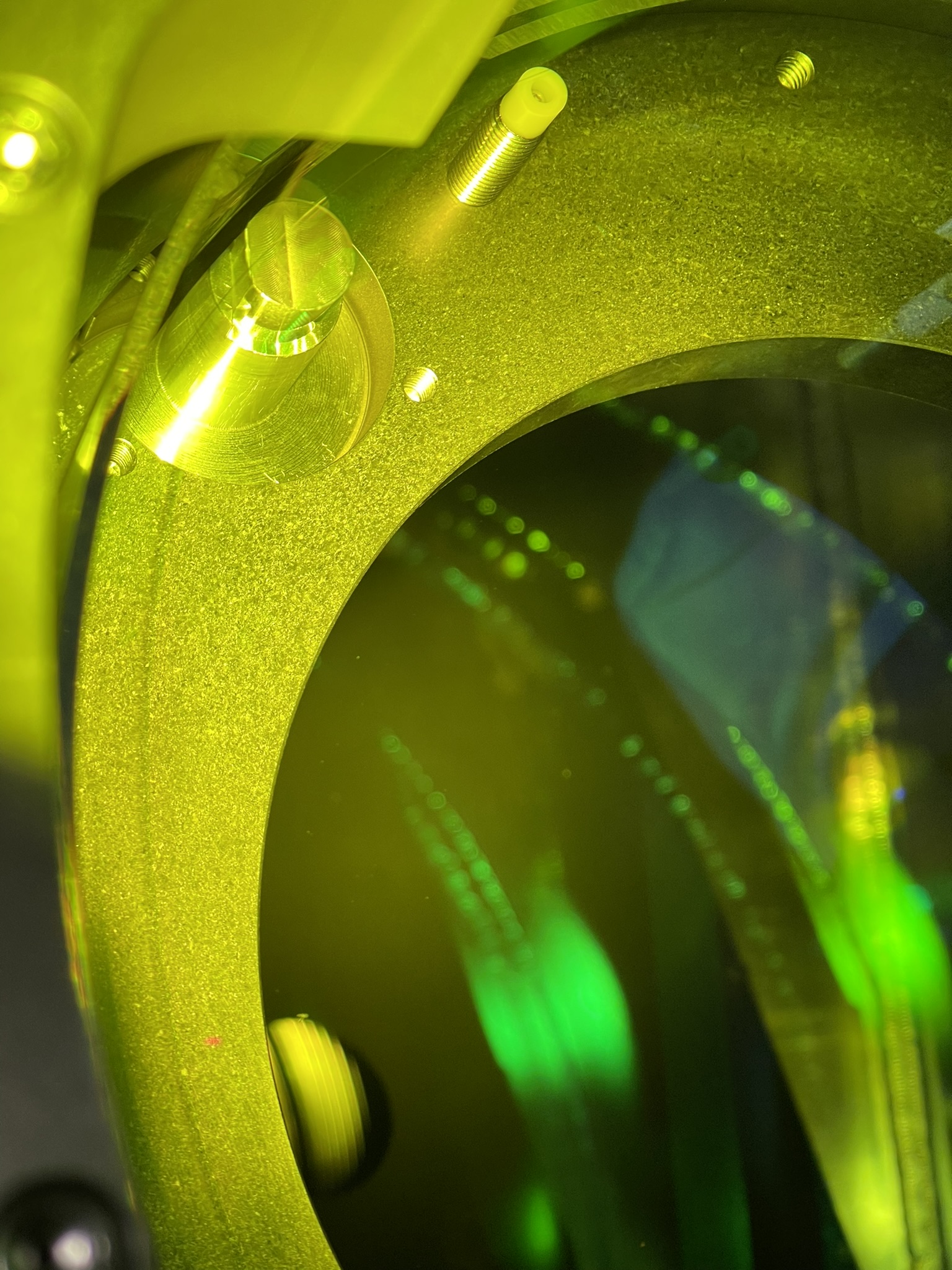
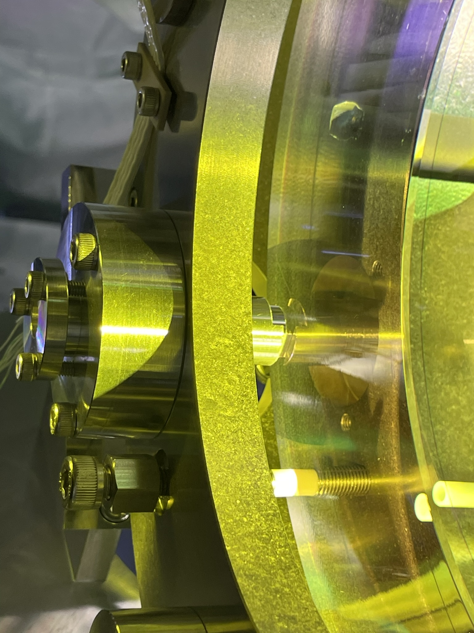
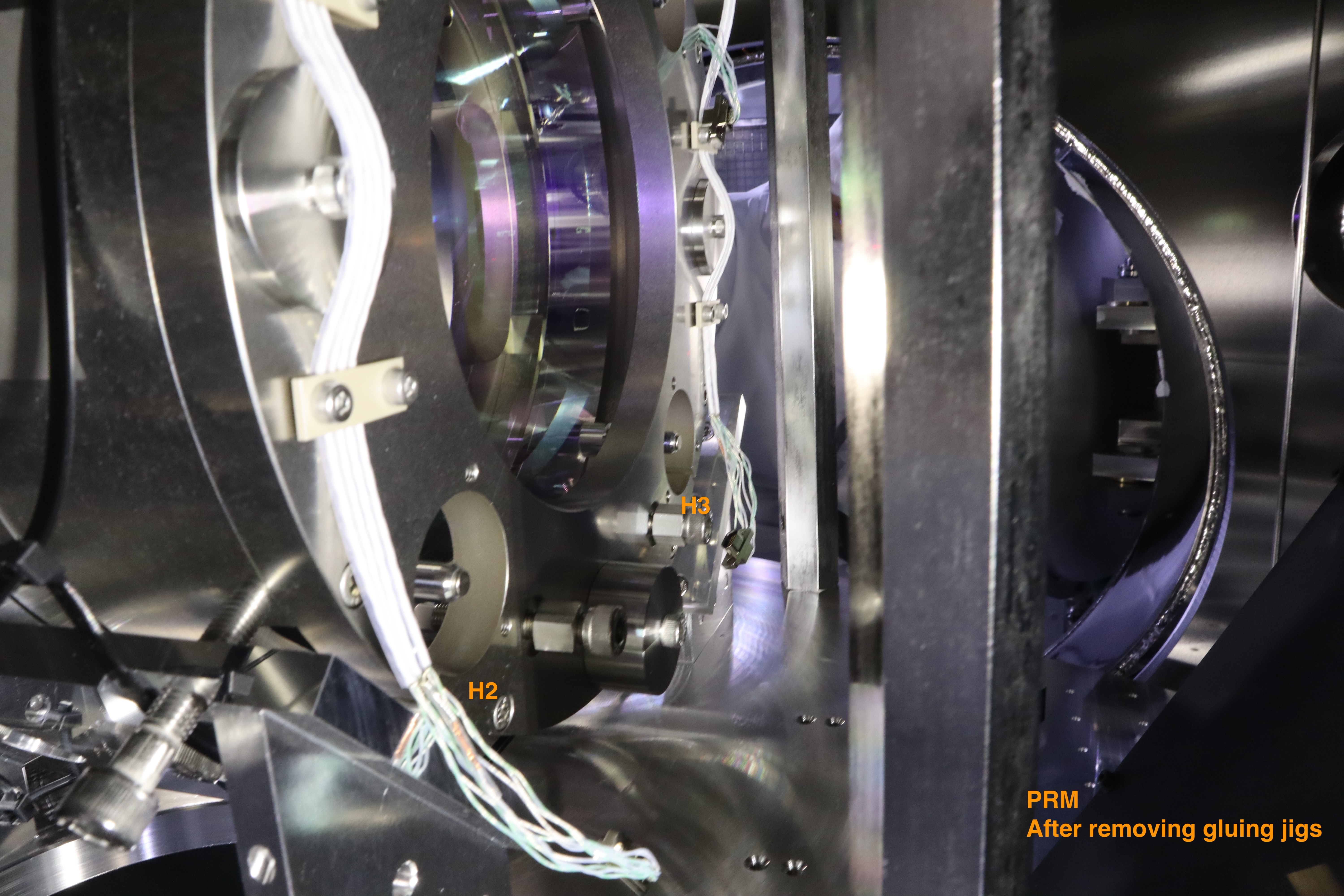
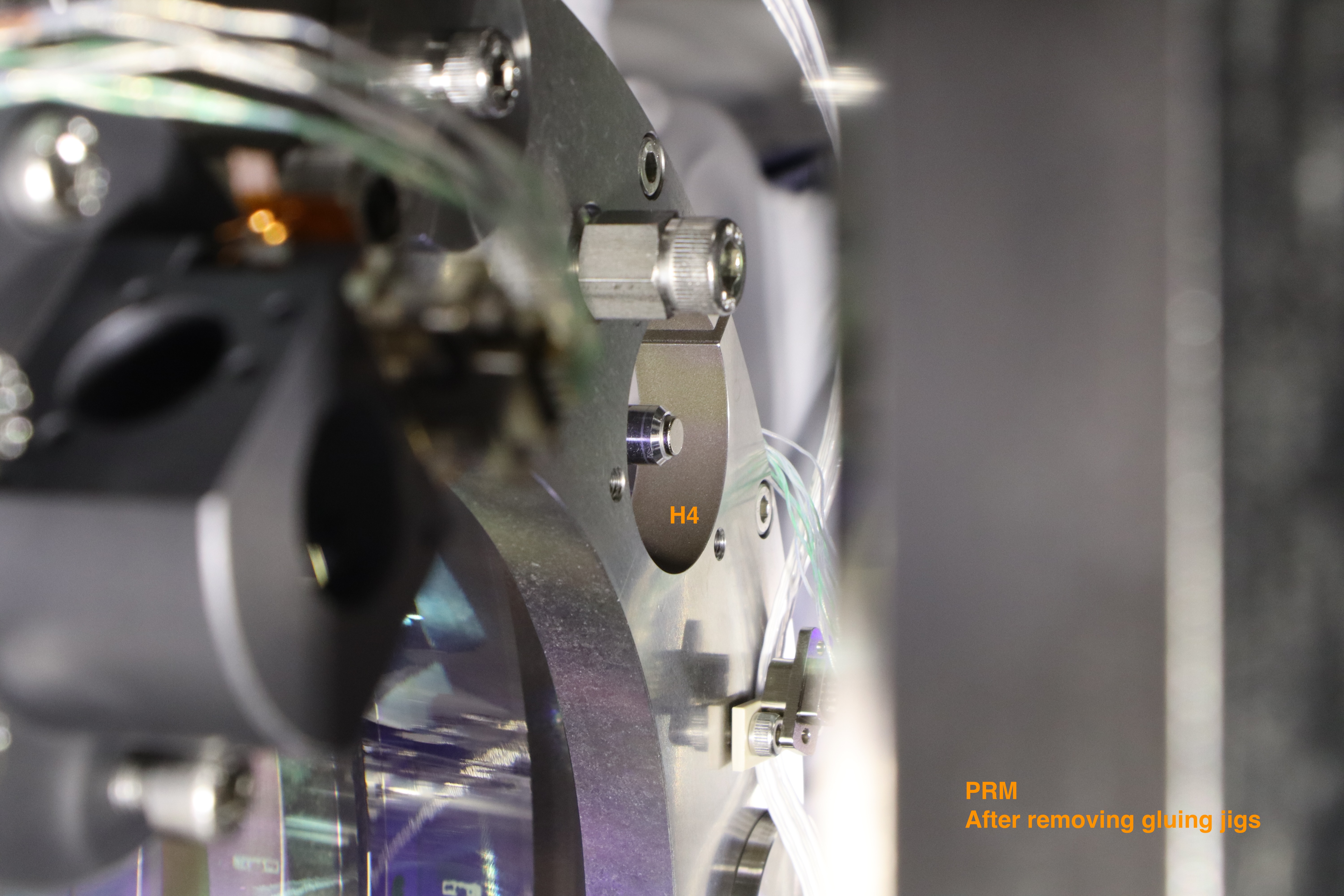
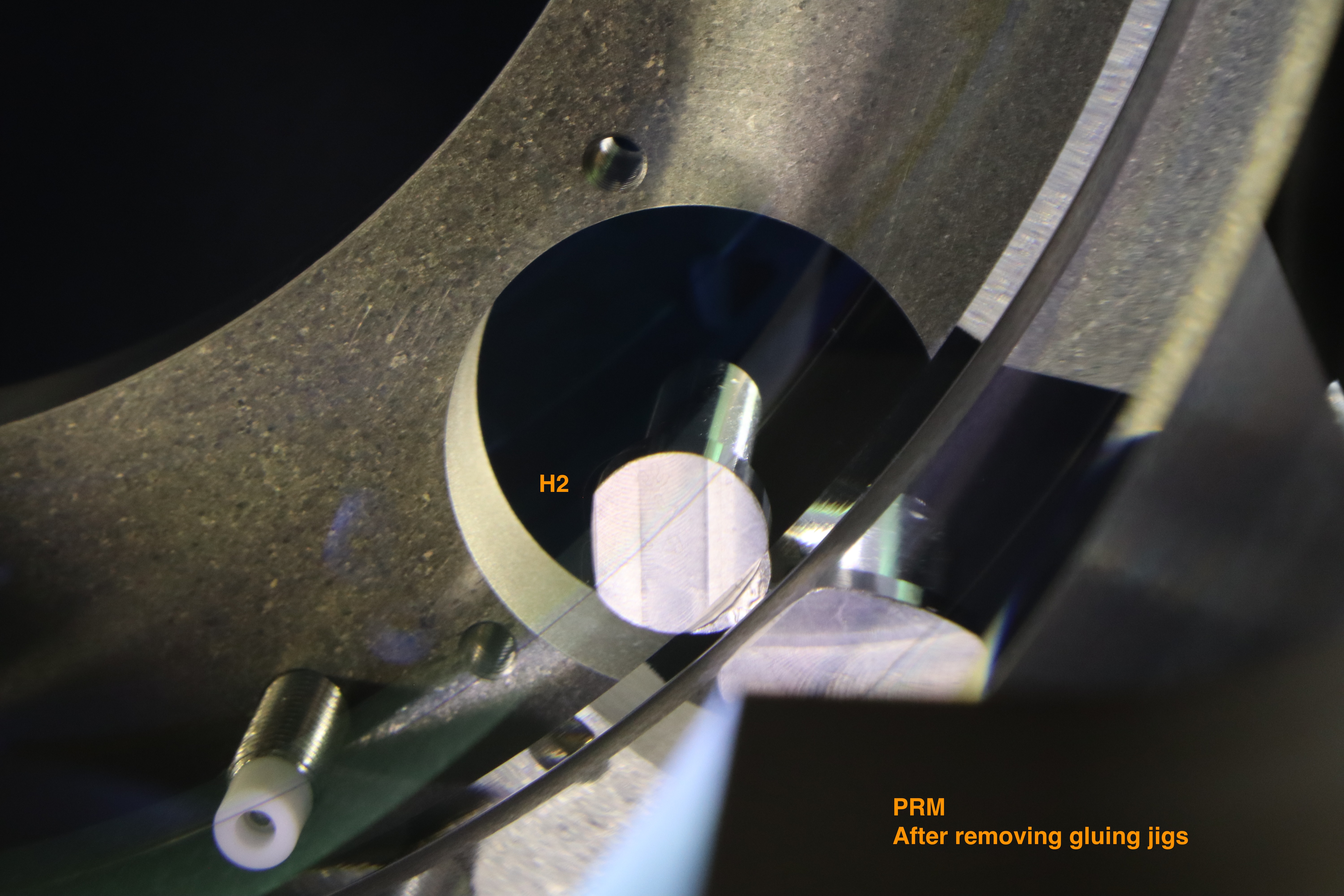
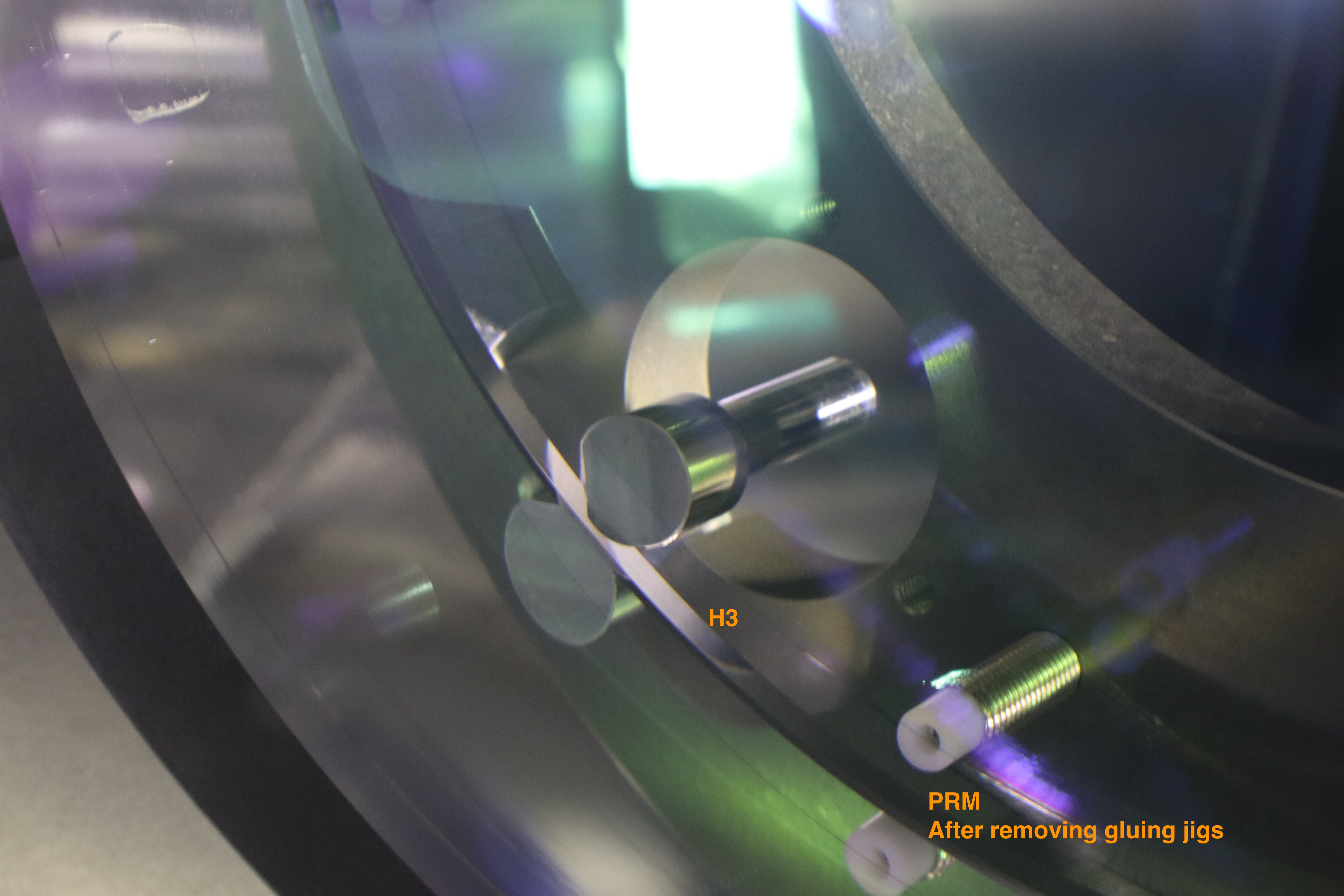
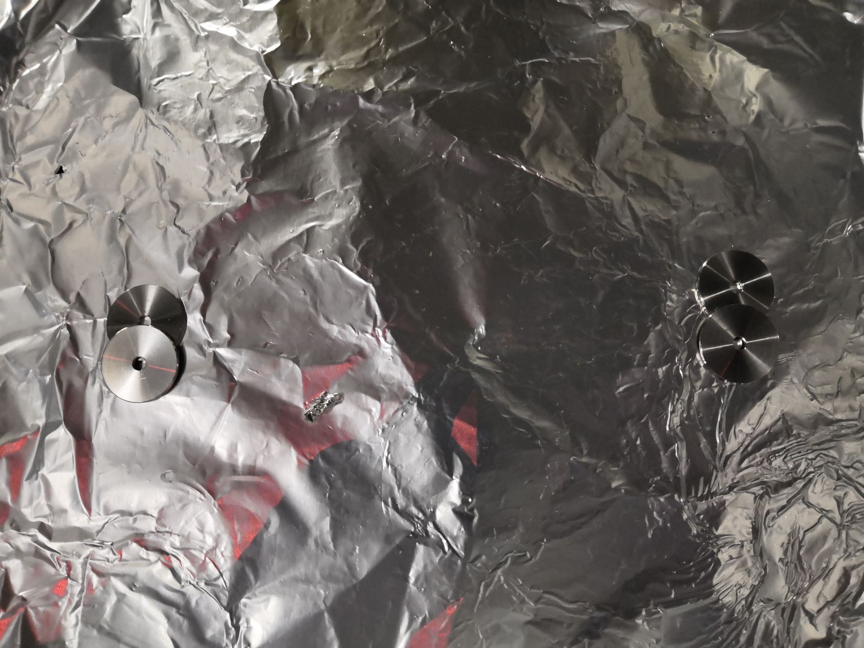
Removal of the gluing jigs
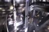
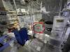
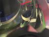
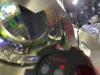
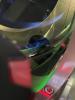
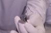
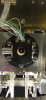
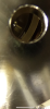
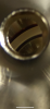
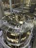
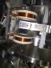
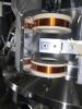
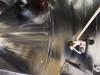
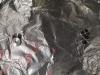
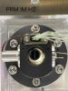
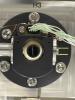
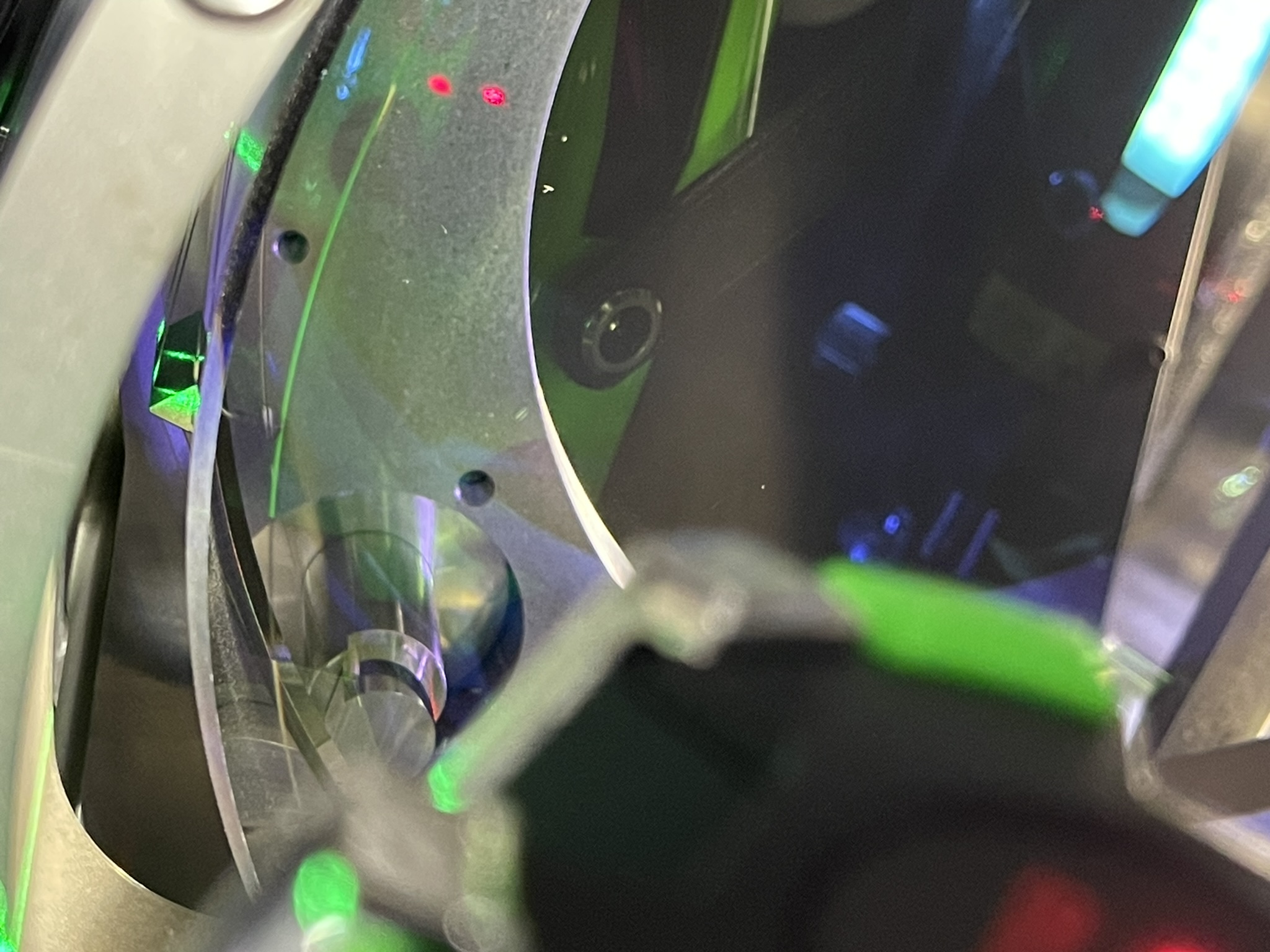
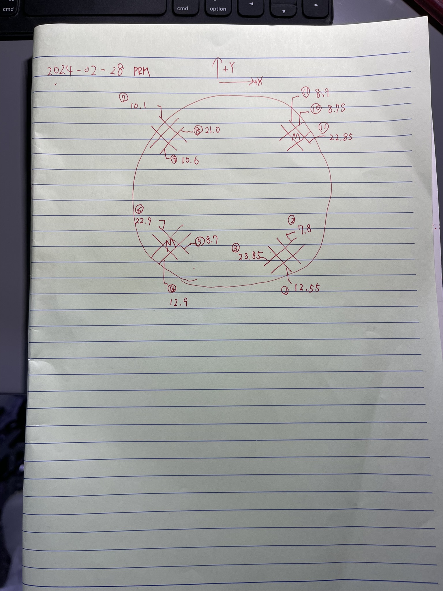
After curing the glue for 24 hours, we removed the gluing jigs from the mirror. All the magnets are bonded well now.
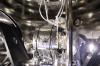
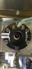
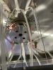
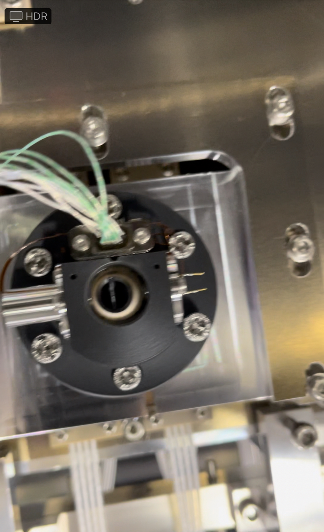
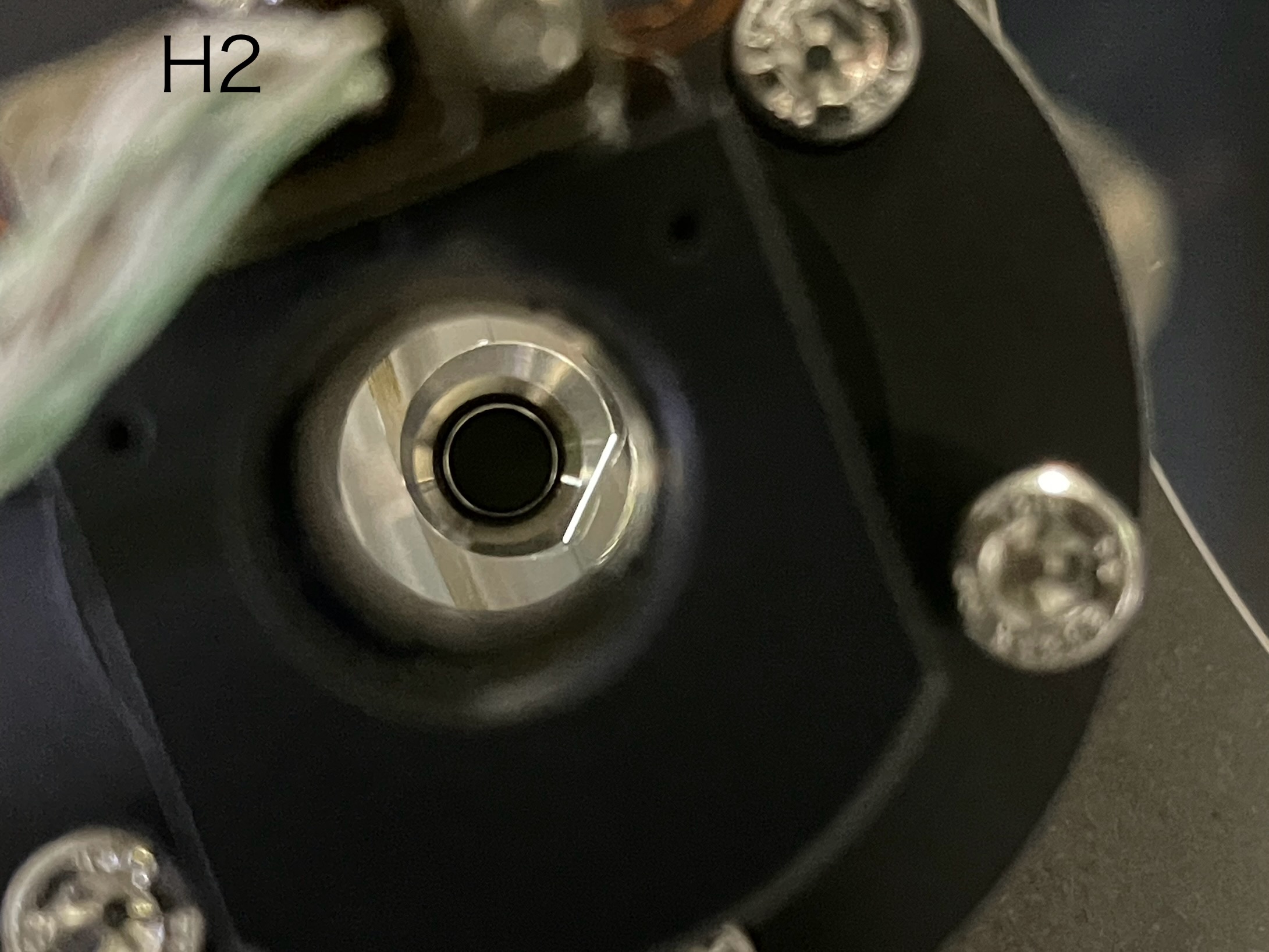
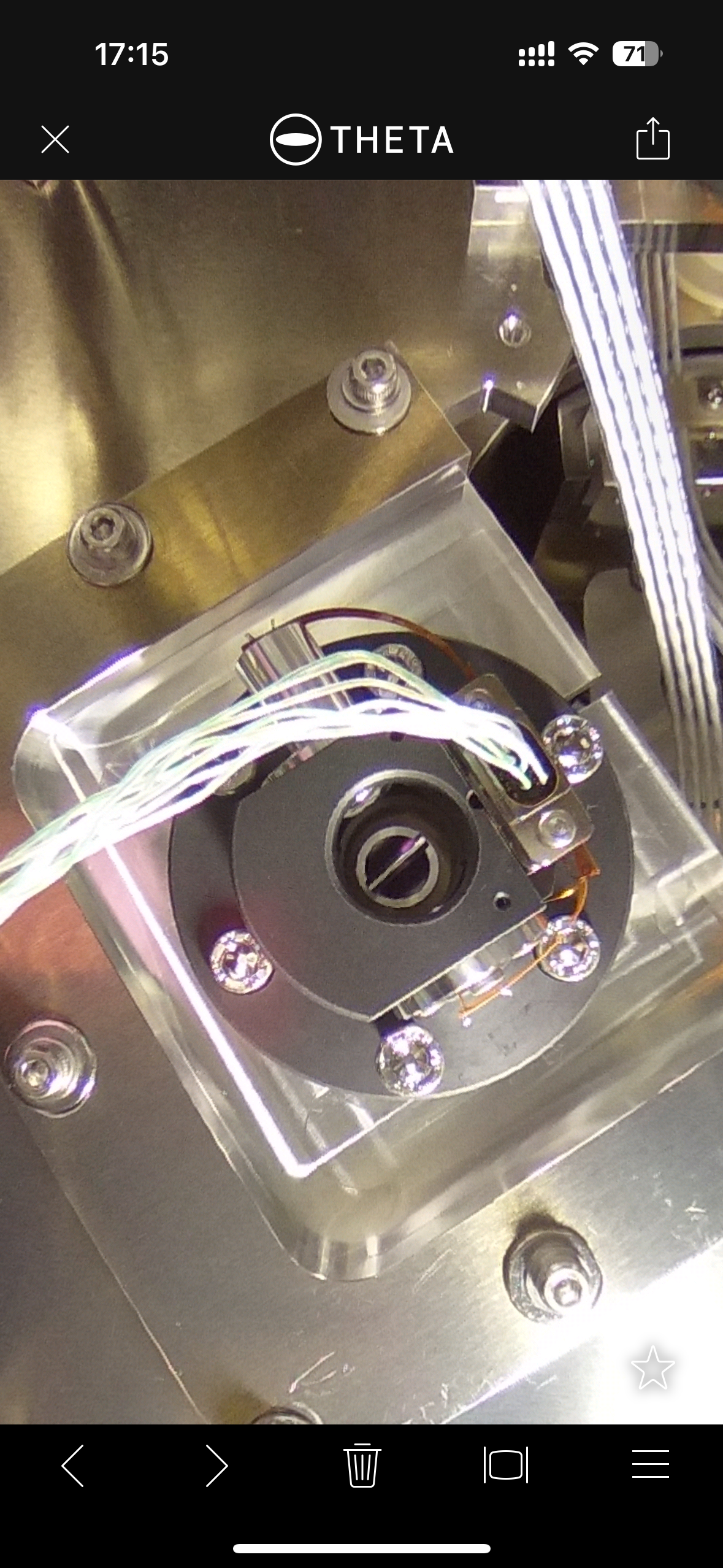
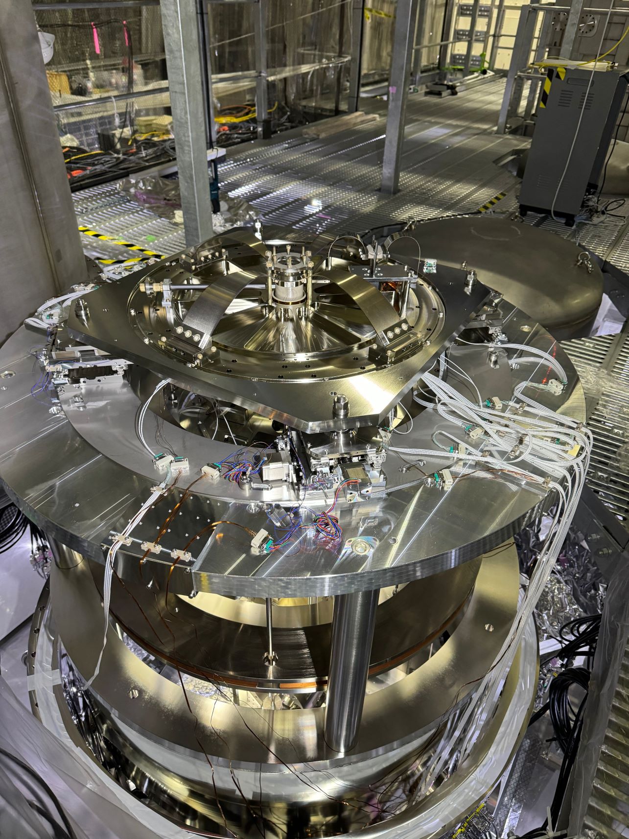
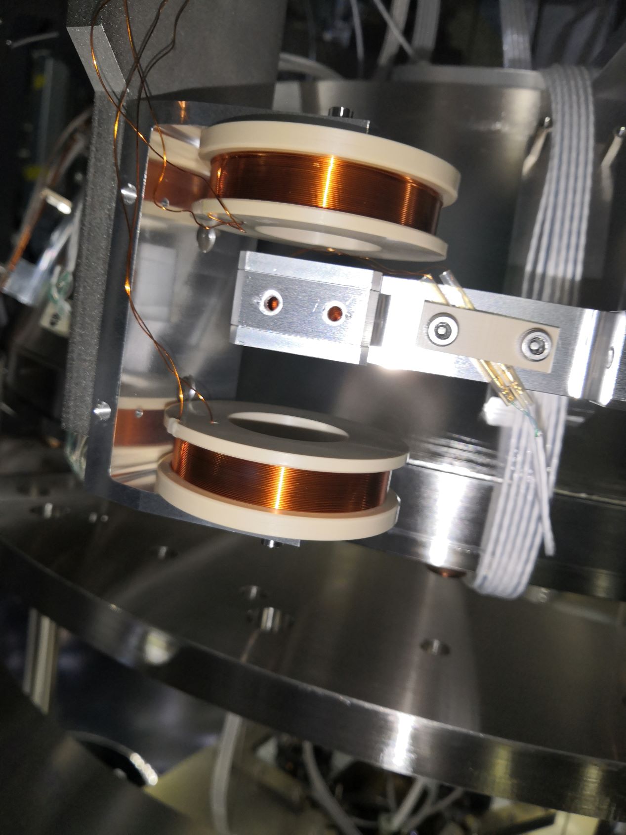
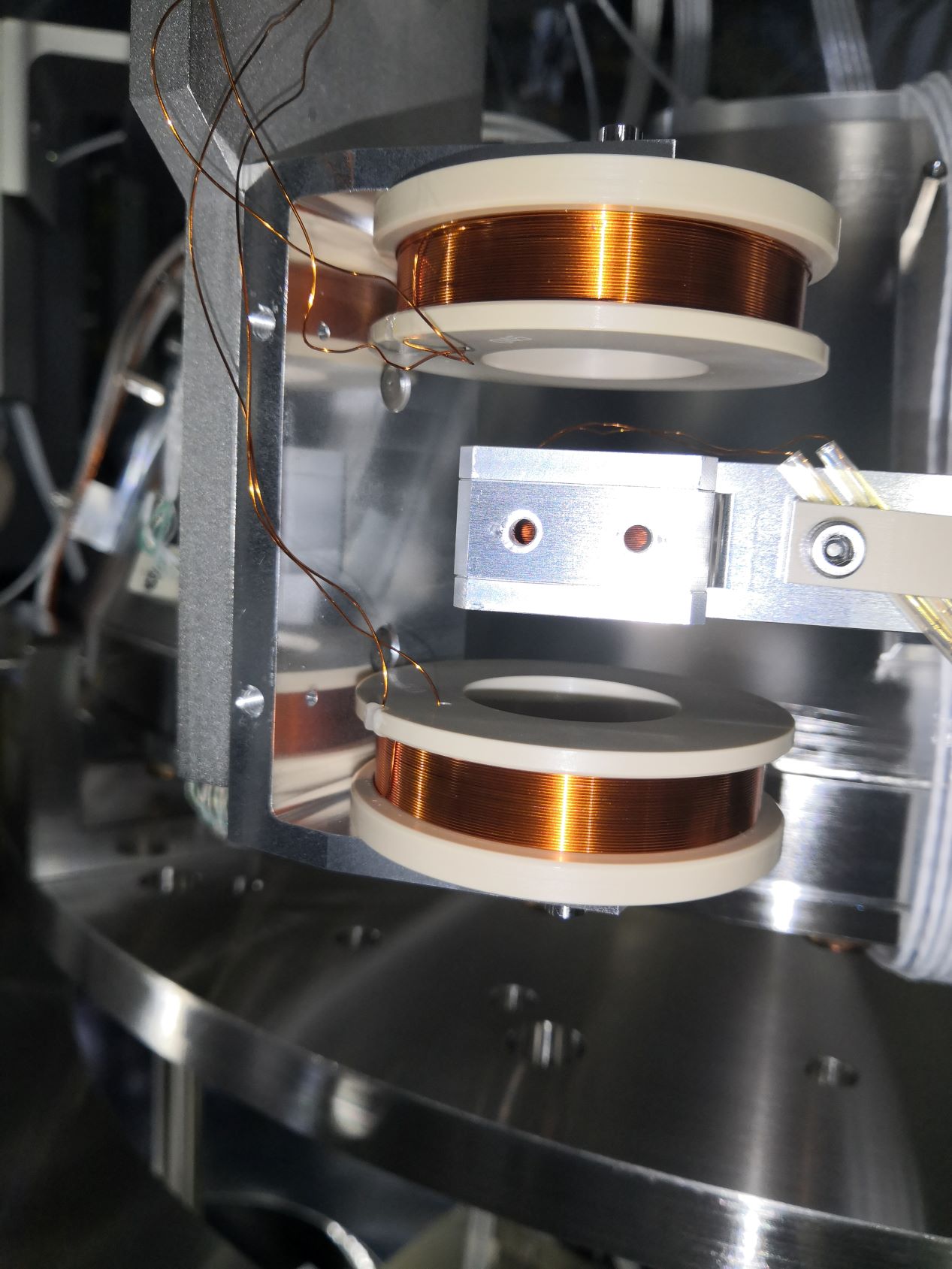
We then put back the coils.
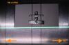
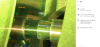
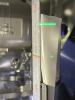
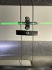
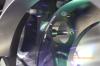
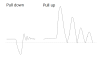
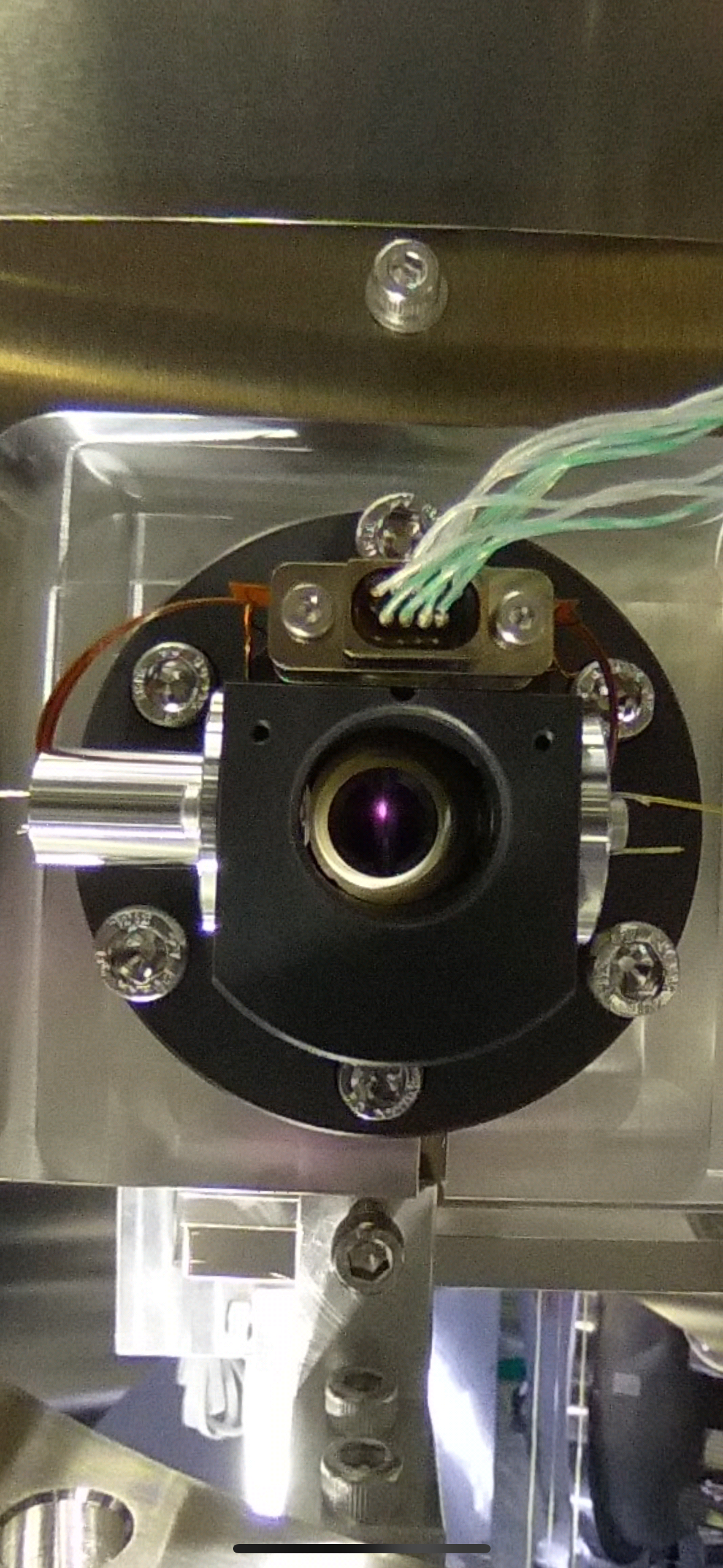
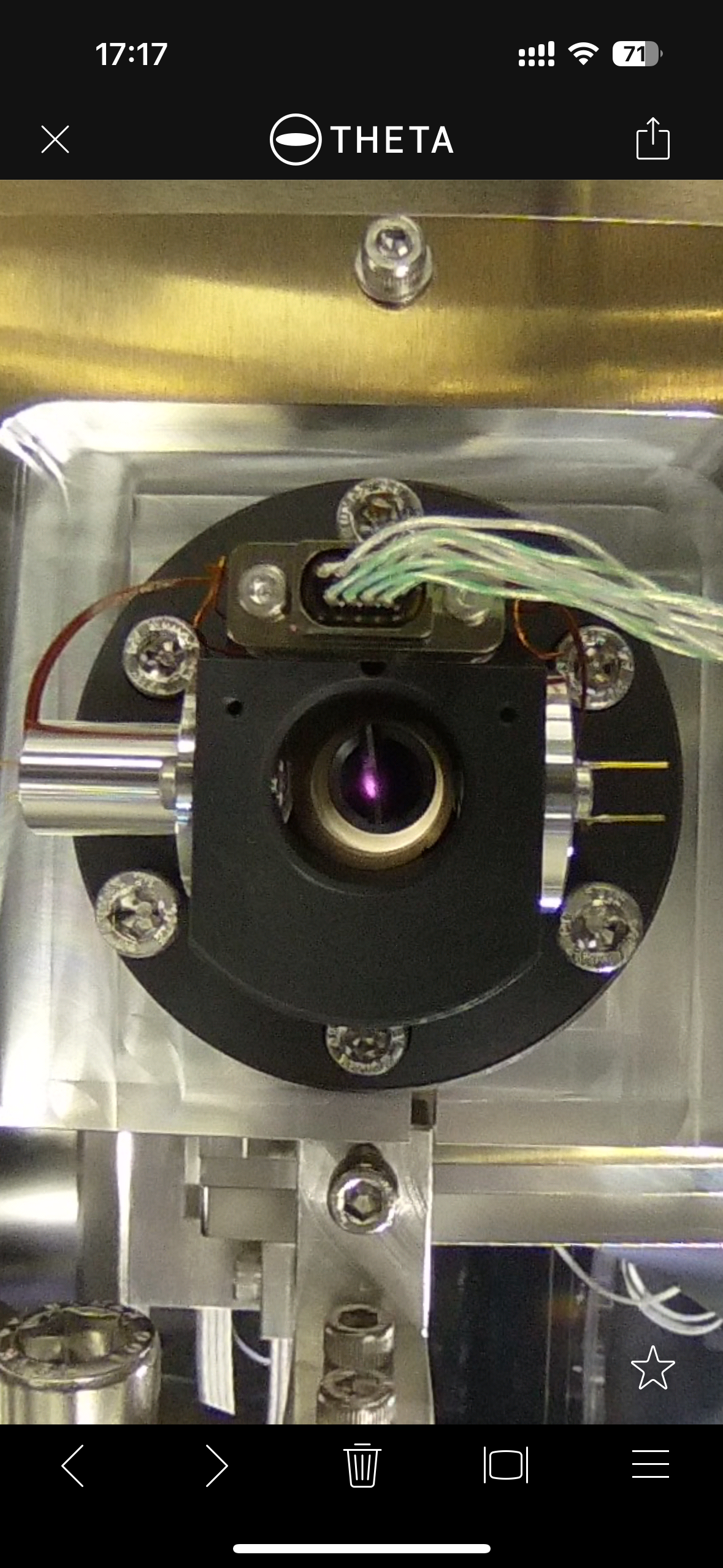
OpLev centering
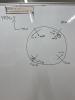
After releasing the mirror, we found that the OpLev beam shifted a lot in downwards. This means the mirror rotated a lot in -pitch, which is expected from the increased weight of the magnets.
The mirror was originally tilted in +pitch a lot. So this is a good sign.
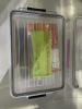
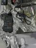
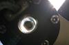
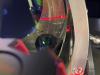
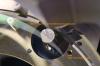
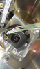
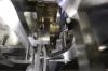
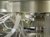
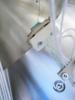
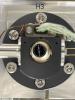
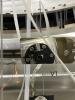
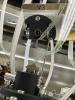
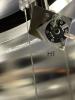
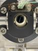
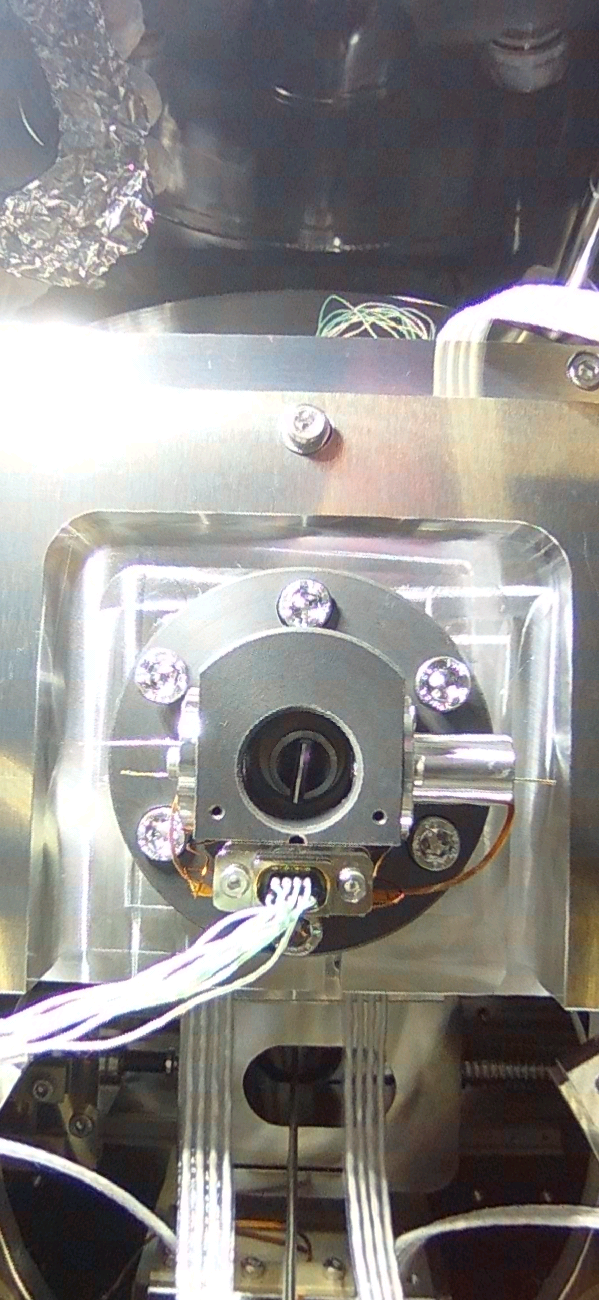
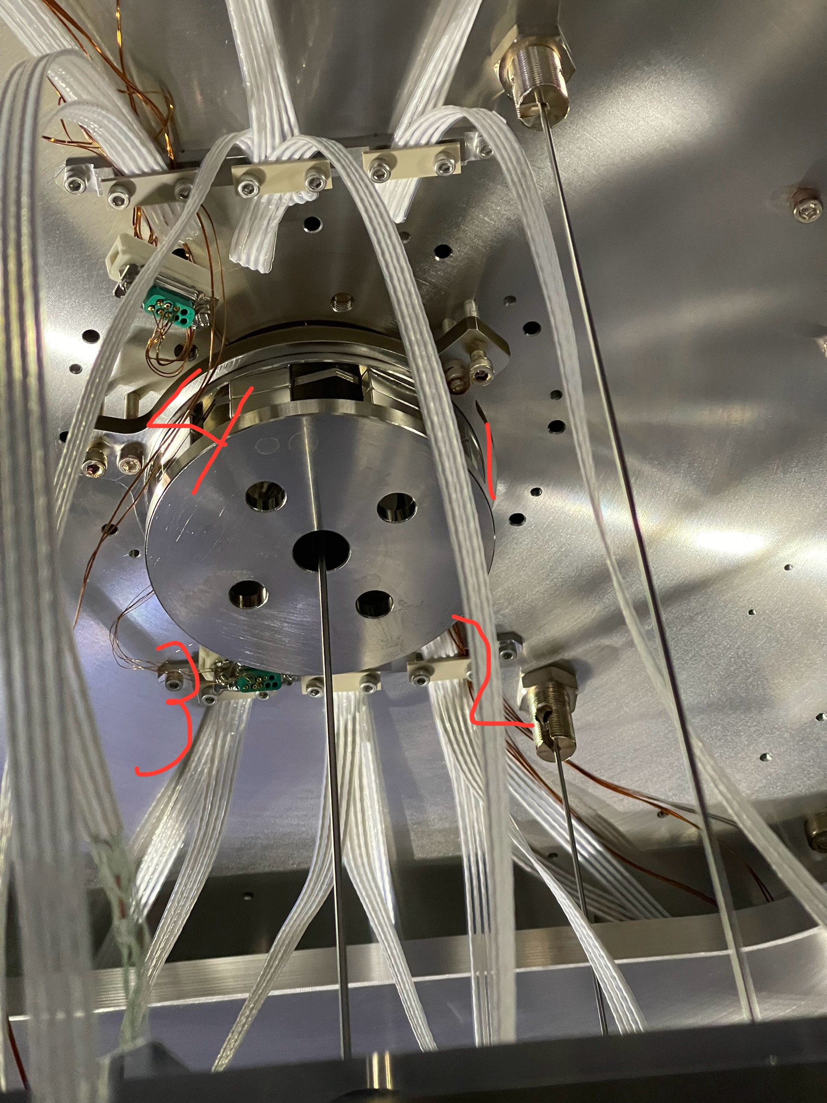
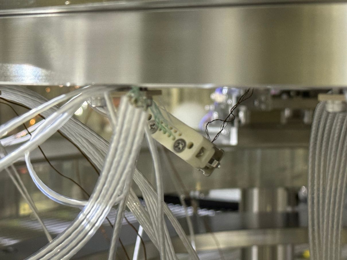
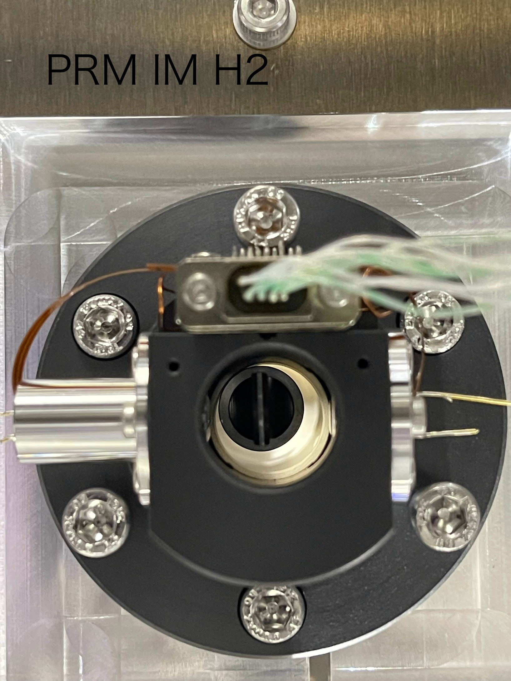
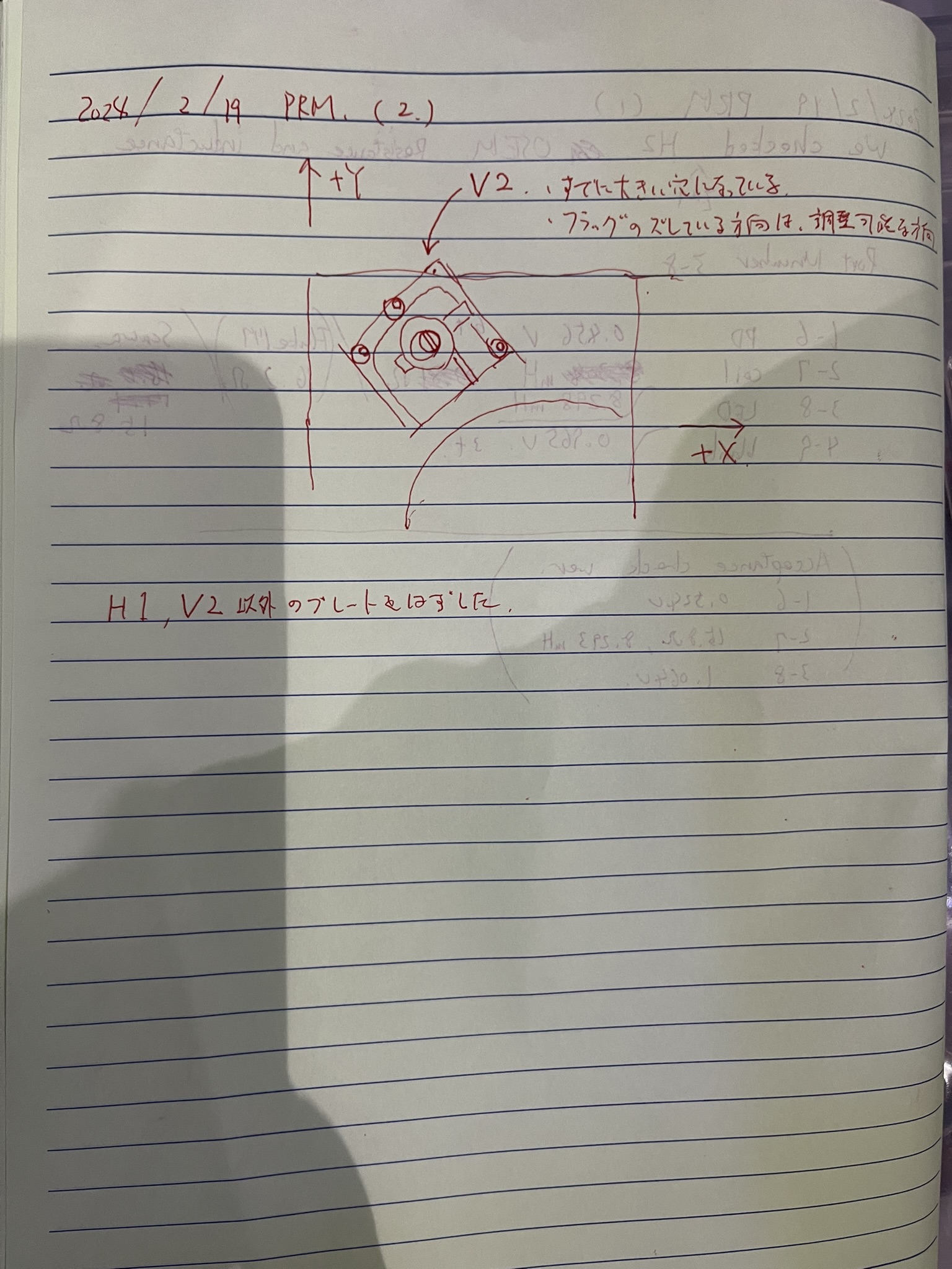
We moved the IM moving mass to recover the OpLev beam centering. Along the way, we had to adjust the positions of the IM OSEMs because some of them were rubbing.
In the end we were able to center the tilt QPD with all the OSEMs in good positions.
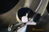
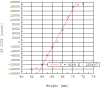
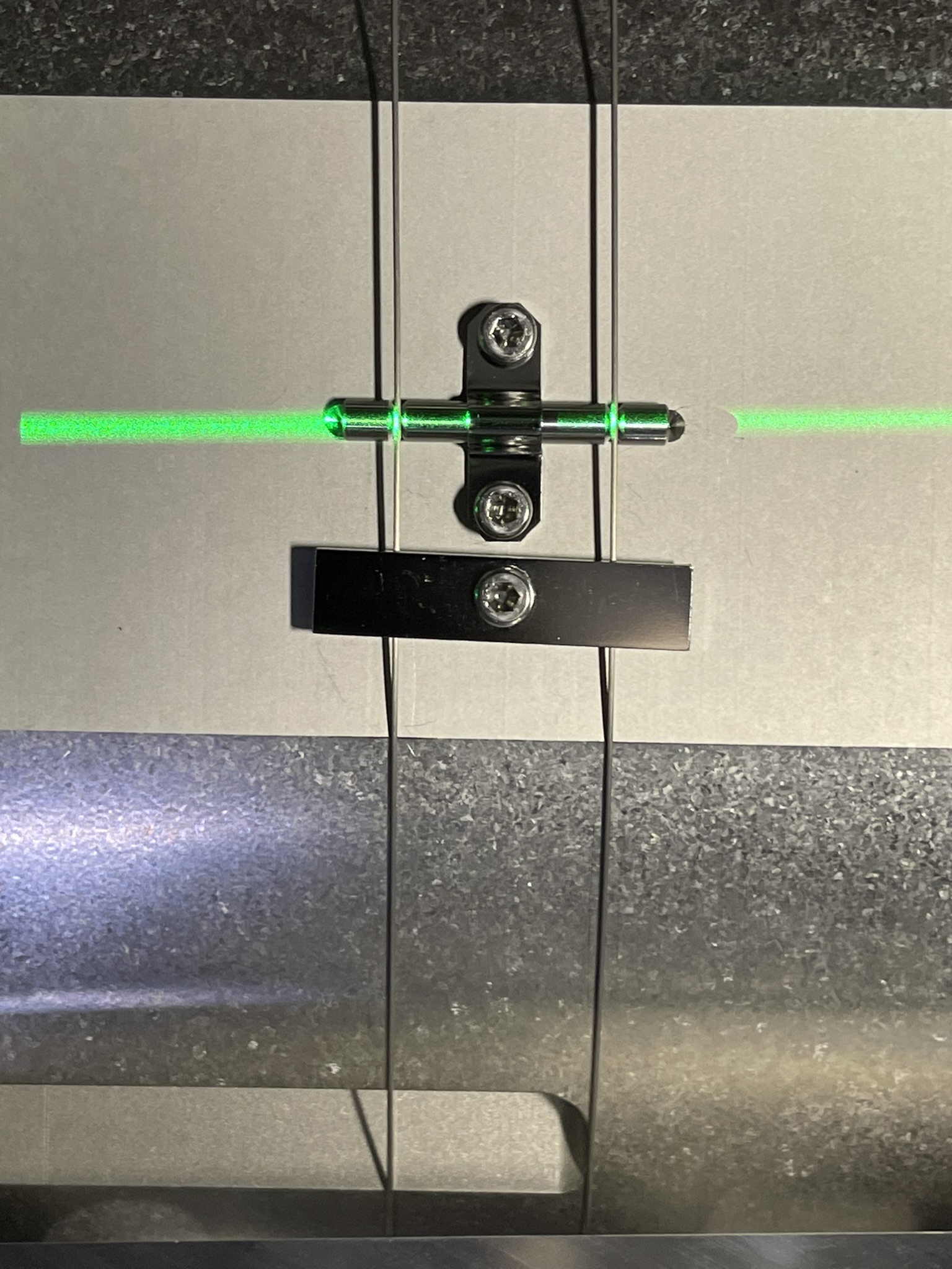
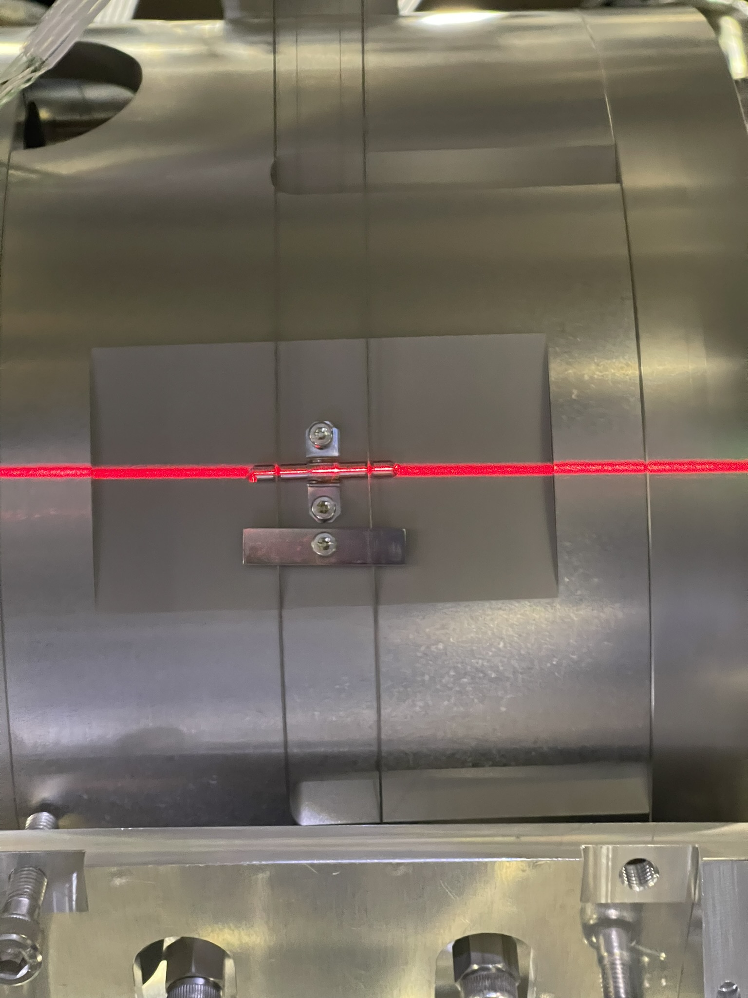
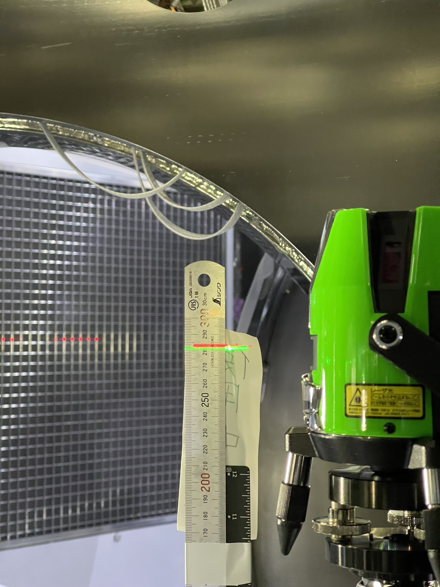
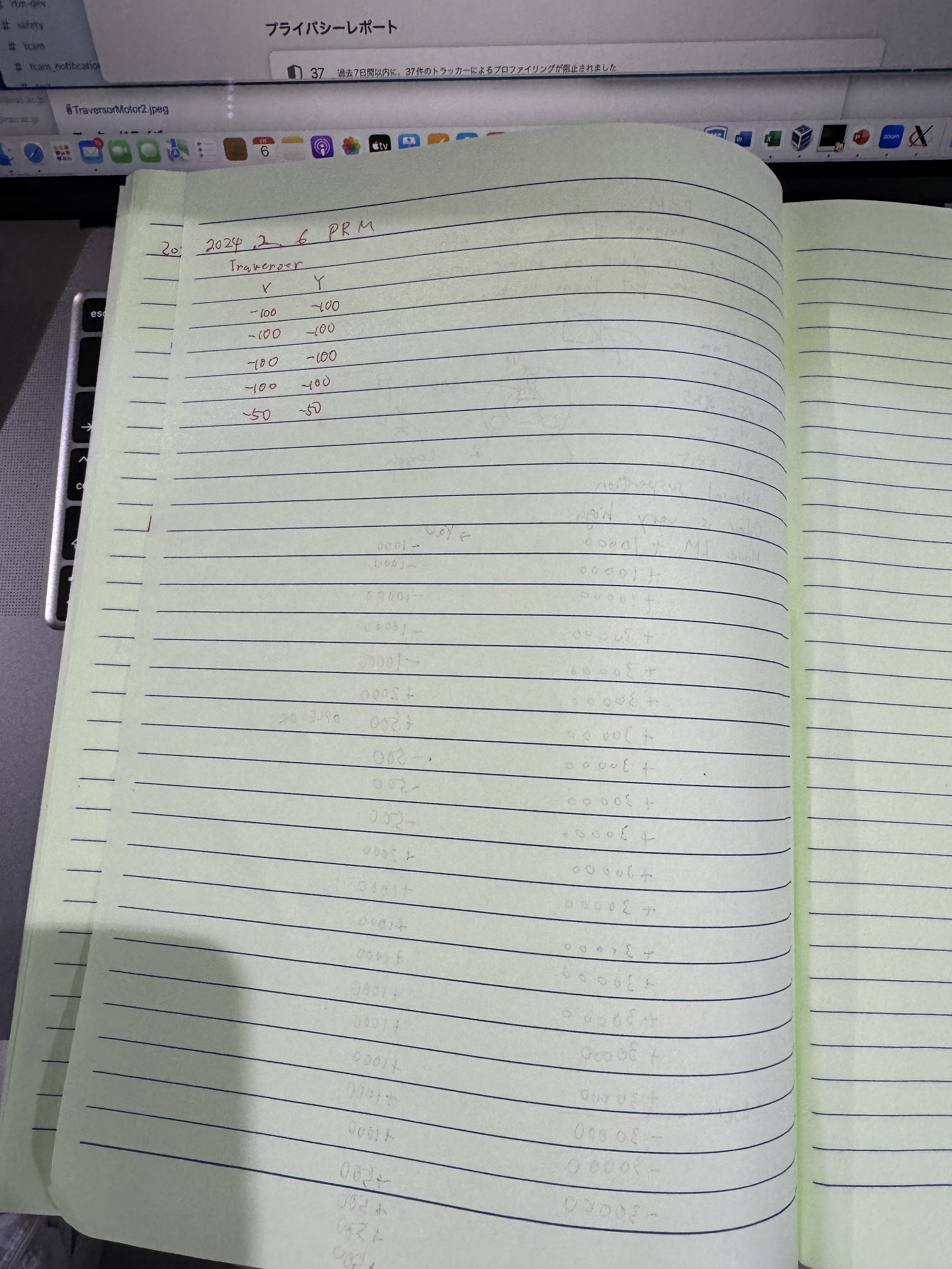
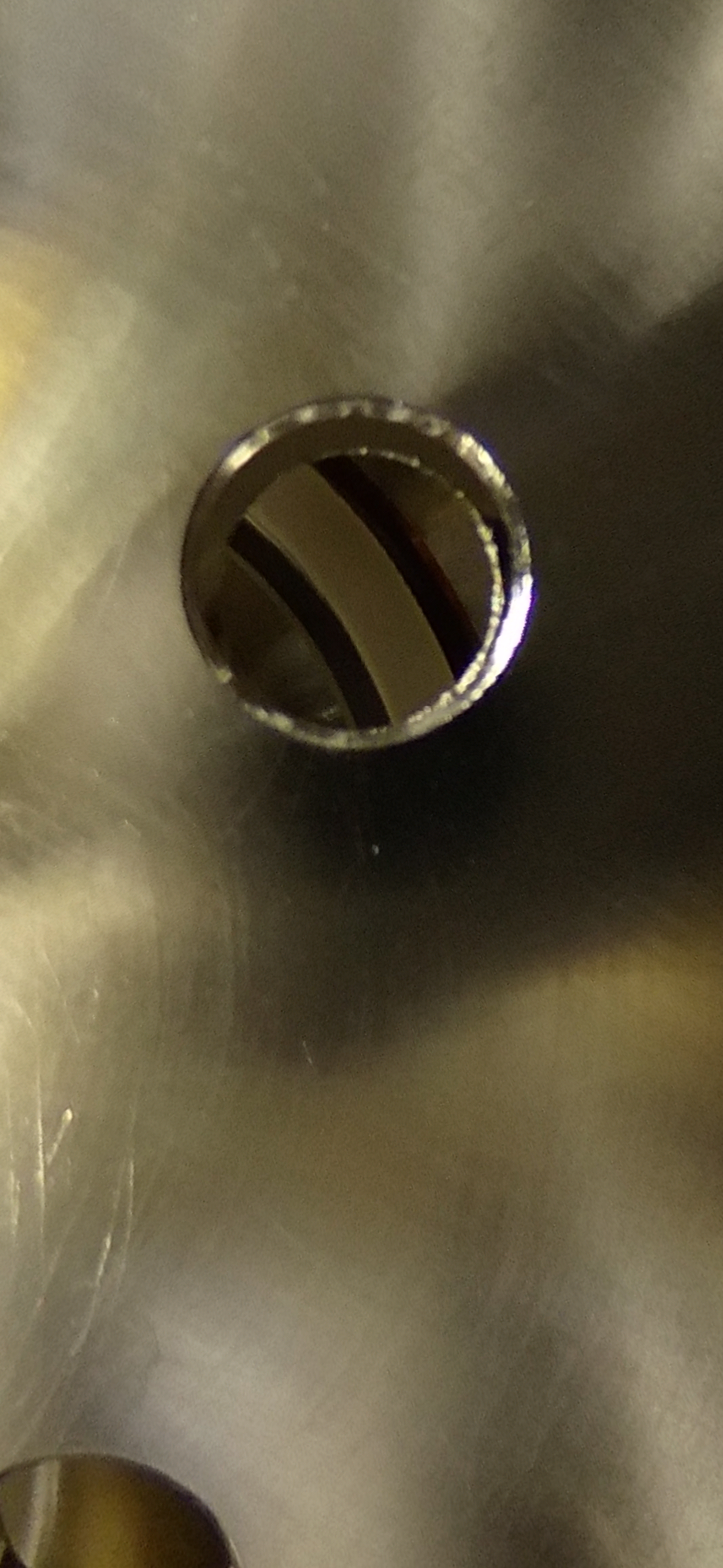
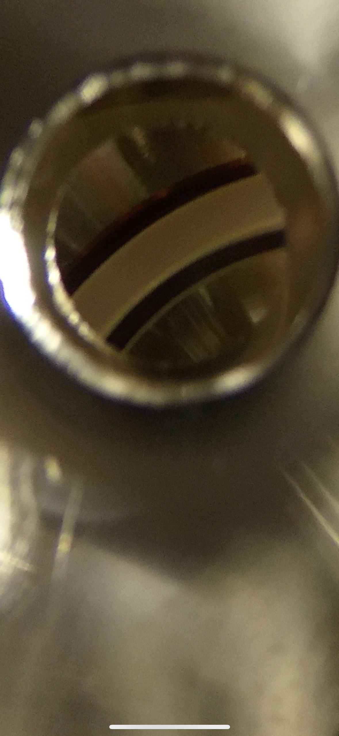
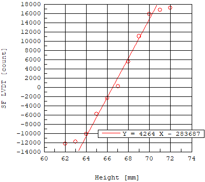
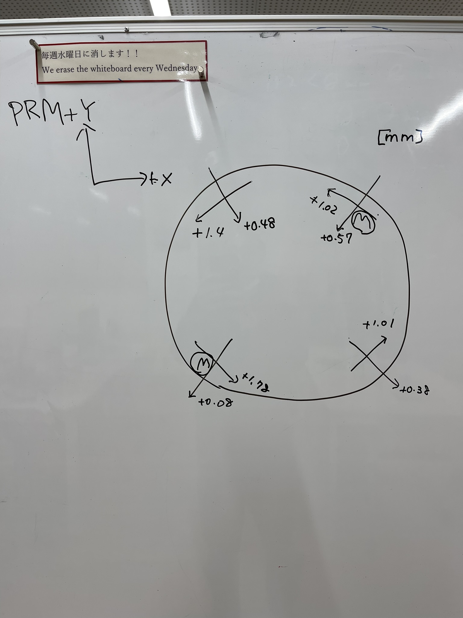
We then found that the LEN OpLev is shifted by ~300.
We corrected this using the traverser just like PR3.
However, even after this, we could not bring the Guardian to the aligned state (oscillation happened).
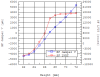
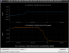
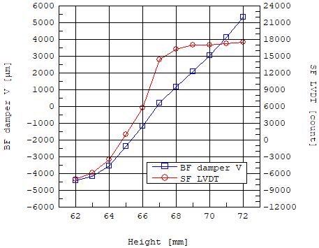
As revealed by Ushiba-san's health check measurements, something must be rubbing and the TFs are quite different from the reference. This is probably why the local damping loops were unstable.


