Akutsu, Takahashi, Aso
Summary
We replaced the in-vac cable for the DCPD to a new one.
We released the OMC.
We installed the bread board dampers.
The OMC alignment was recovered.
We confirmed that the OMC can be locked.
The OMC transmission was about 95%.
Details
Cable replacement
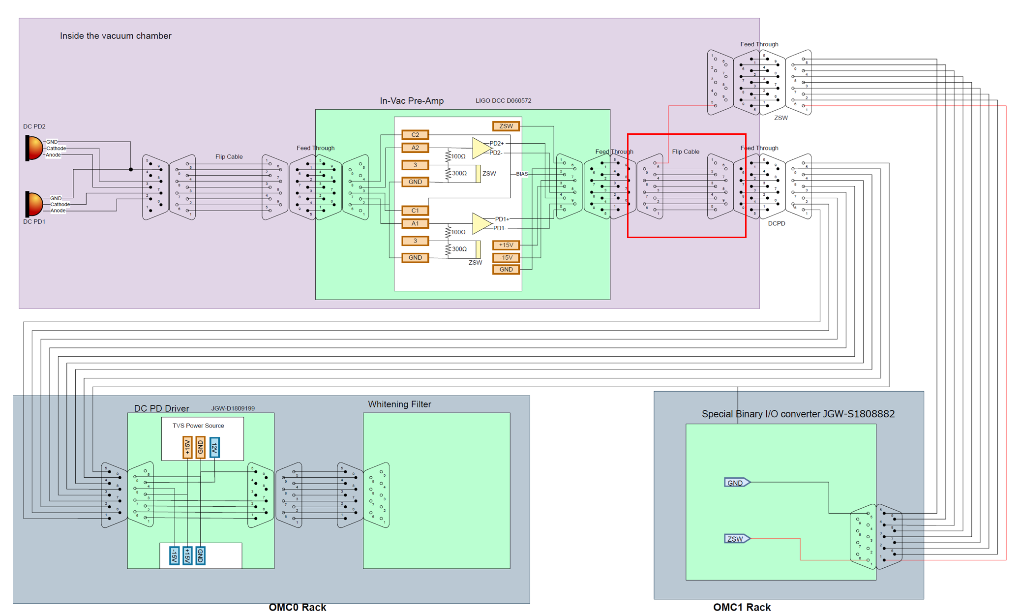
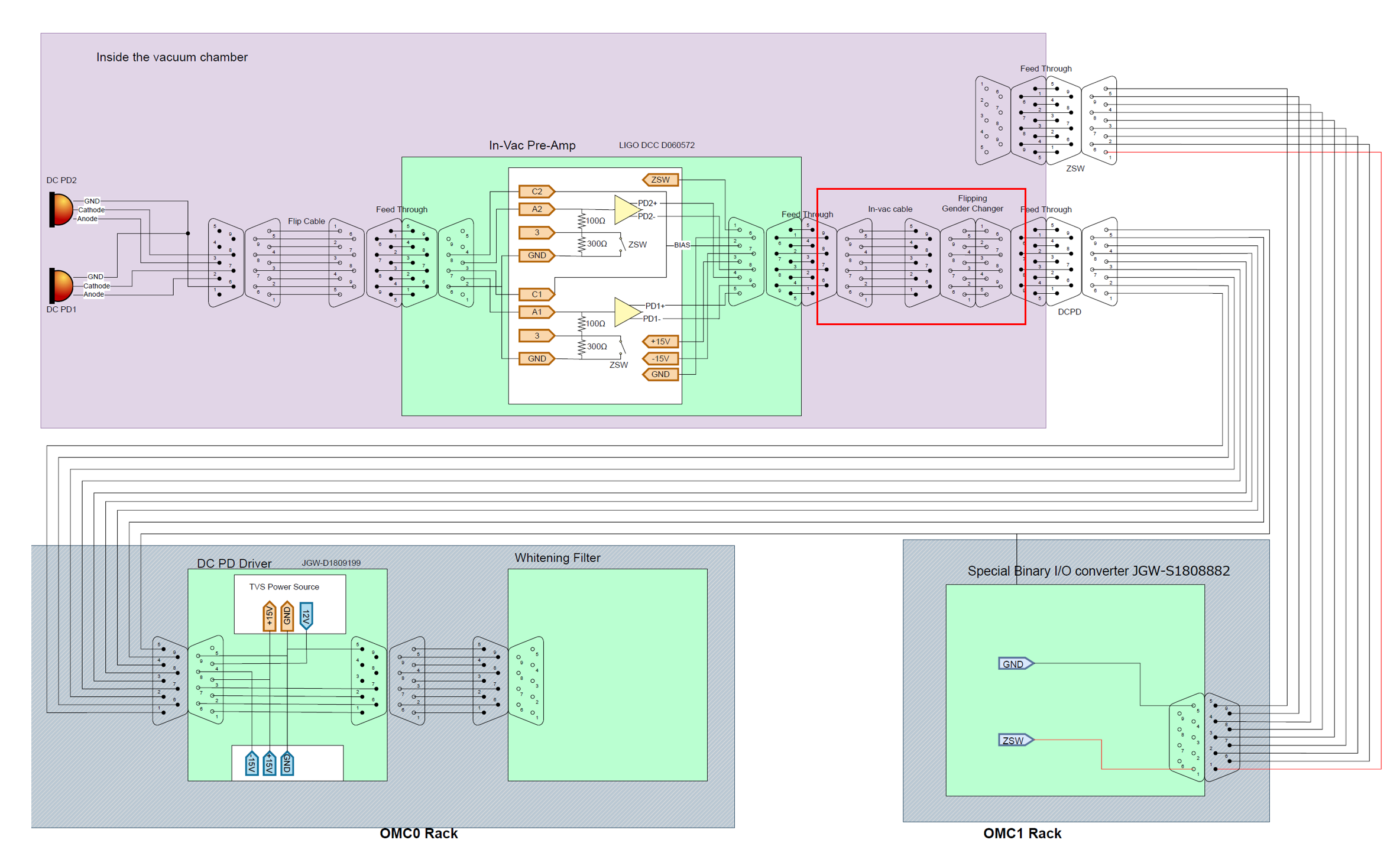
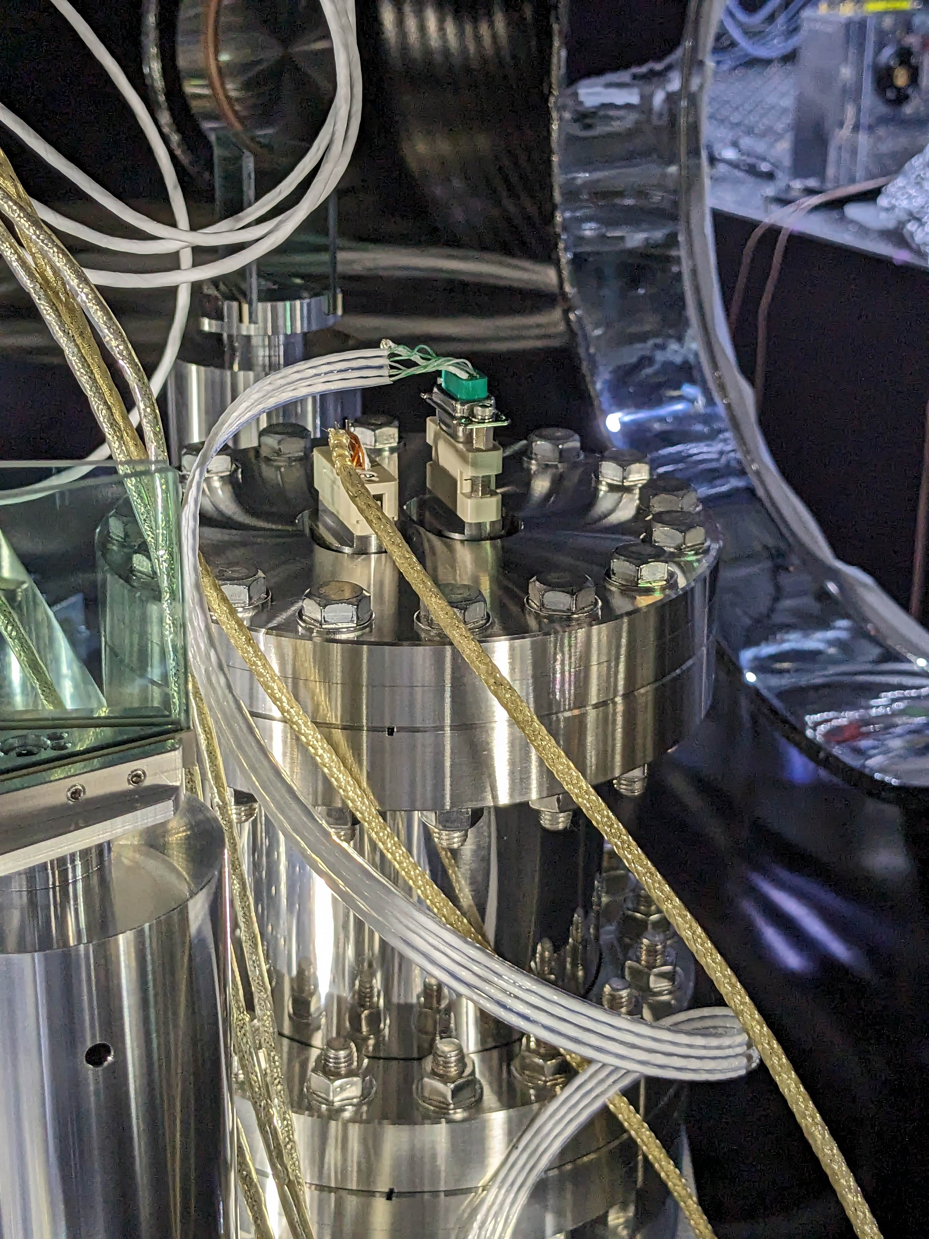
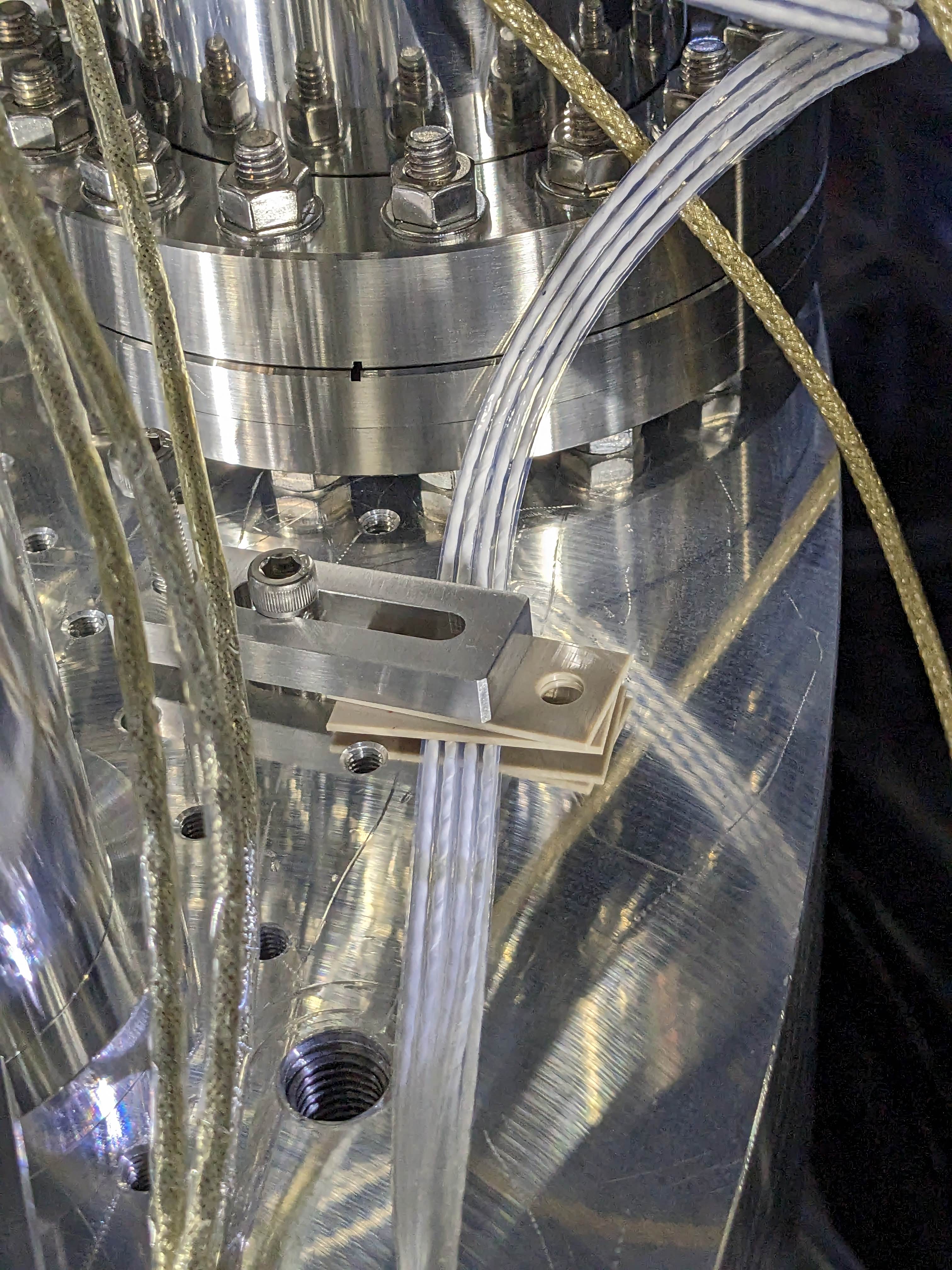
We replaced the in-vac cable connecting the feedthrough flange and the DCPD pre-amp with a new cable.
The white flat cable is the new cable. The brownish cables are original cables of OMC.
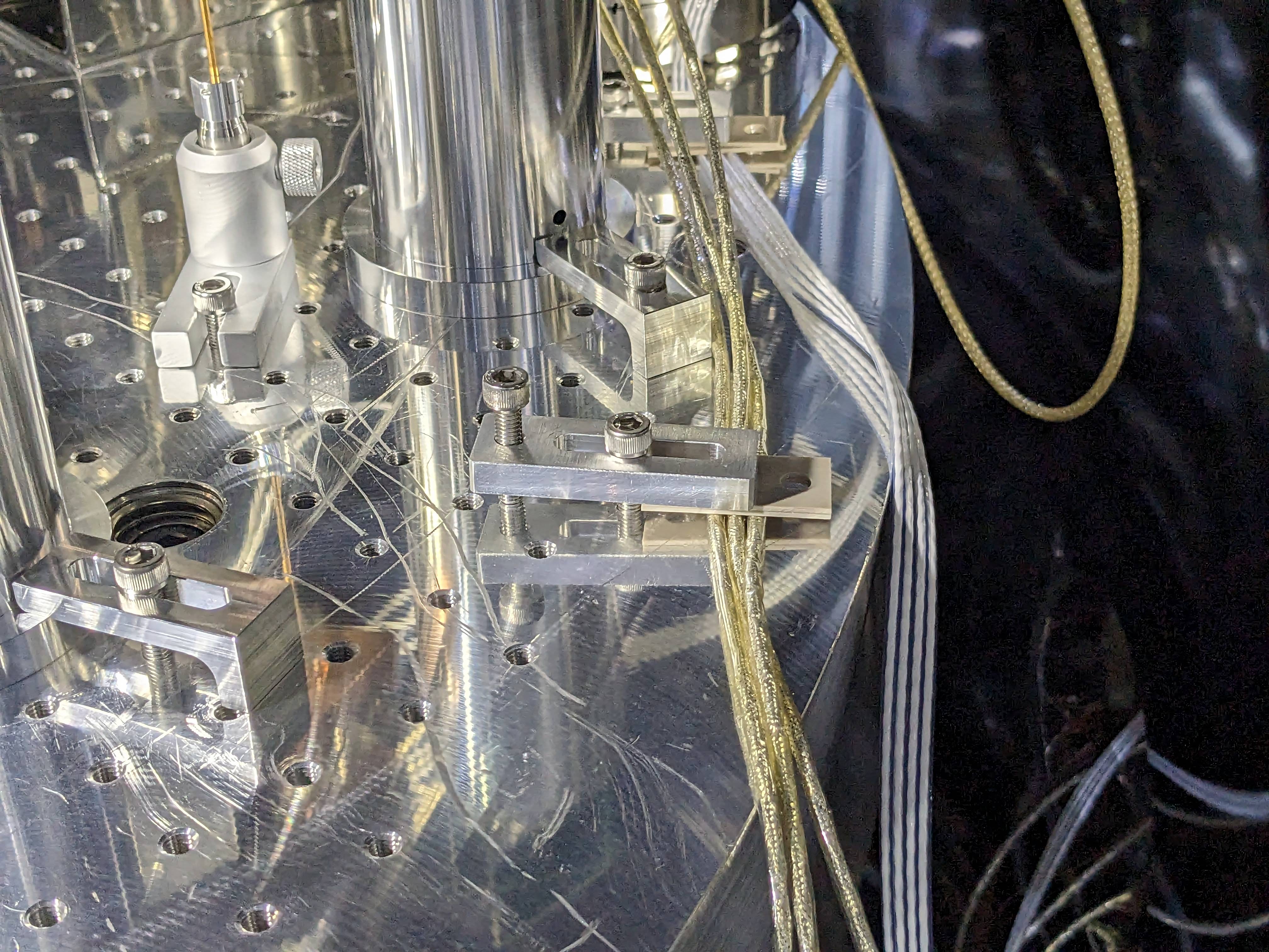
Fixing the cables
We anchored the OMC cables on the optical table, which is vibration isolated by a stack.
Installation of the bread board dampers
To be reported separately
OMC alignment recovery
After releasing the OMC suspension, we locked the interferometer in the single arm mode.
The IFO AS beam was hitting the OMC QPDs. So the OMC alignment had not been so much changed.
We used picomotors to center the OMMT2 transmission QPDs with OMMT1, then centered the OMC QPDs with OMMT2 and OSTM.
OMC lock confirmation
We first measured the input power to the OMC, just after the OFI, with a power meter. It was 36mW.
Then we closed all the doors of the chamber and turned off most of the cleanbooth filters leaving only one of them running.
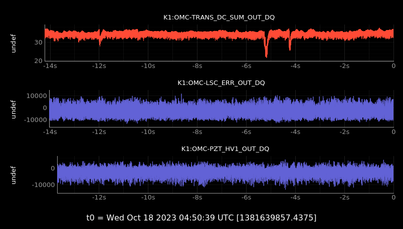
We then locked the OMC to TEM00 mode. The transmission power, using the same calibration factor as before the replacement of the PDs, was 34mW. Therefore, the transmissivity is about 95%.
Below are the spectra of the OMC LSC error and feedback signals.
https://klog.icrr.u-tokyo.ac.jp/osl/uploads/27245_1697620416_Spectra-All.pdf
https://klog.icrr.u-tokyo.ac.jp/osl/uploads/27245_1697620420_Spectra-Zoom.pdf
