Cont'd from 17154.
Abstract
Relocated the periscope on the POP table so that PR2_TRANS_FORWARD will be picked off with another periscope in the future. Send the green beam from the relocated persicope via POP-POM through the PR2 center to the PR3 center.
Relocating the periscope
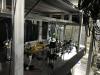
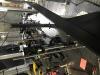
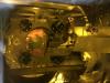
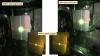
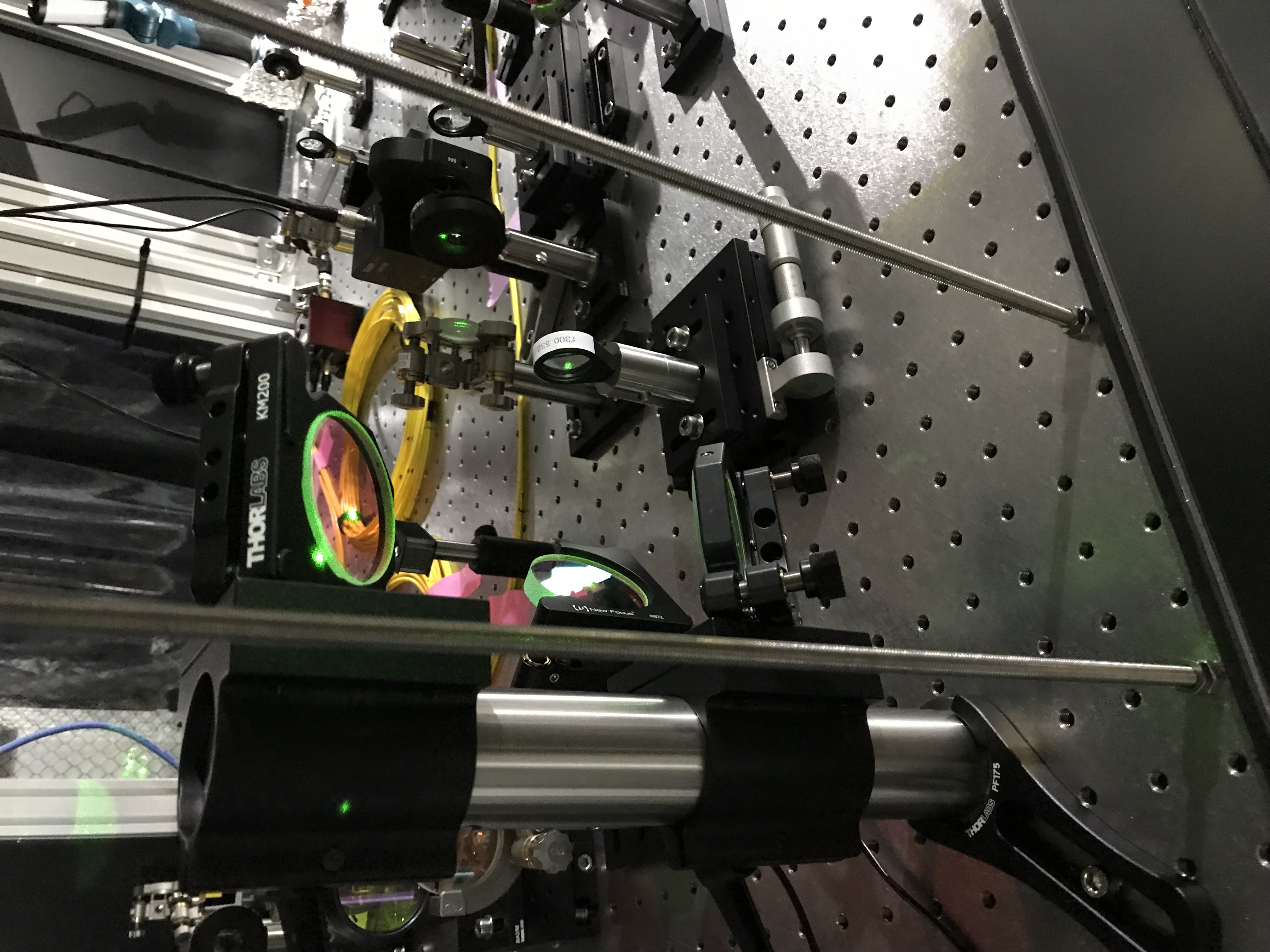
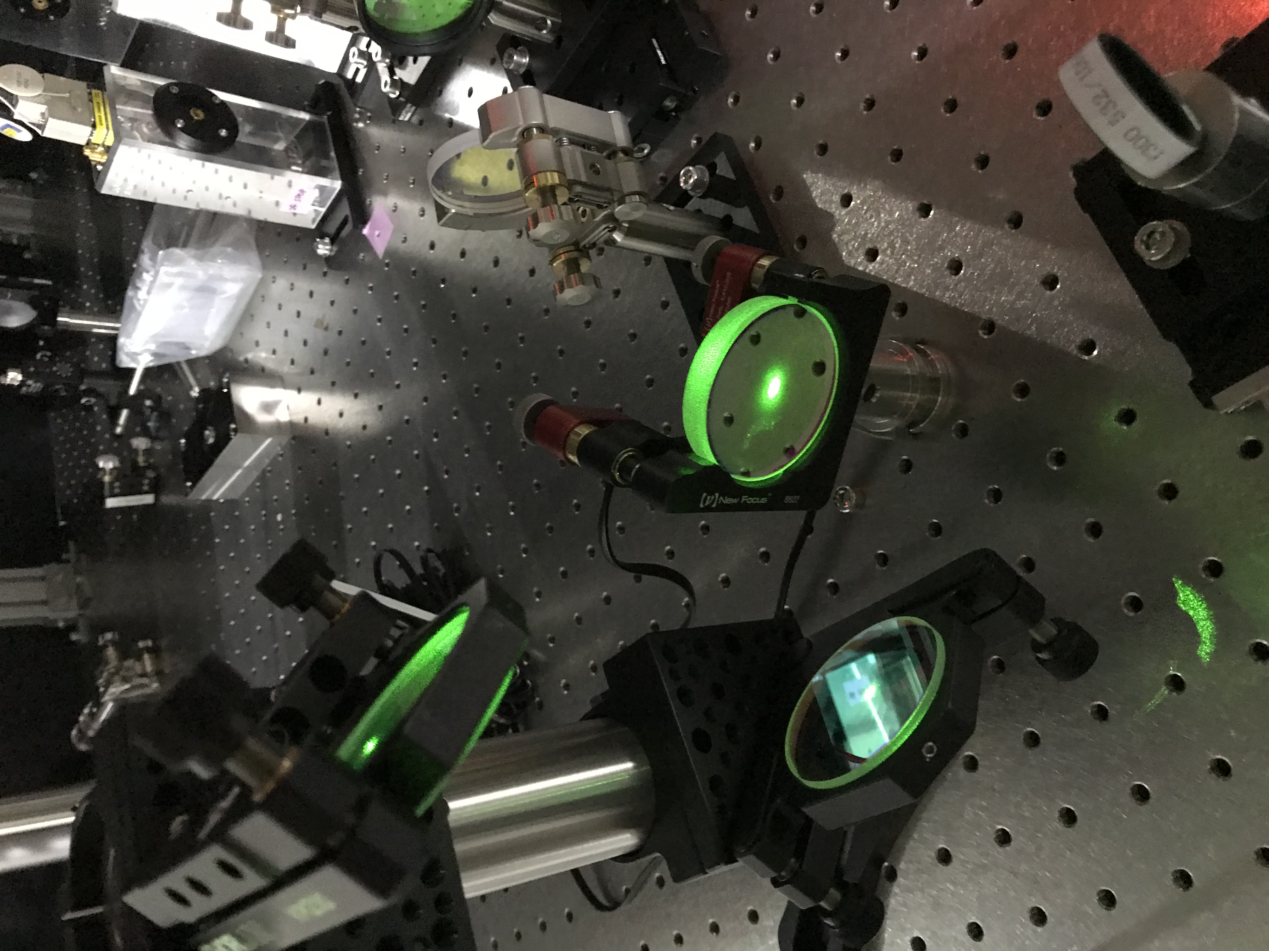
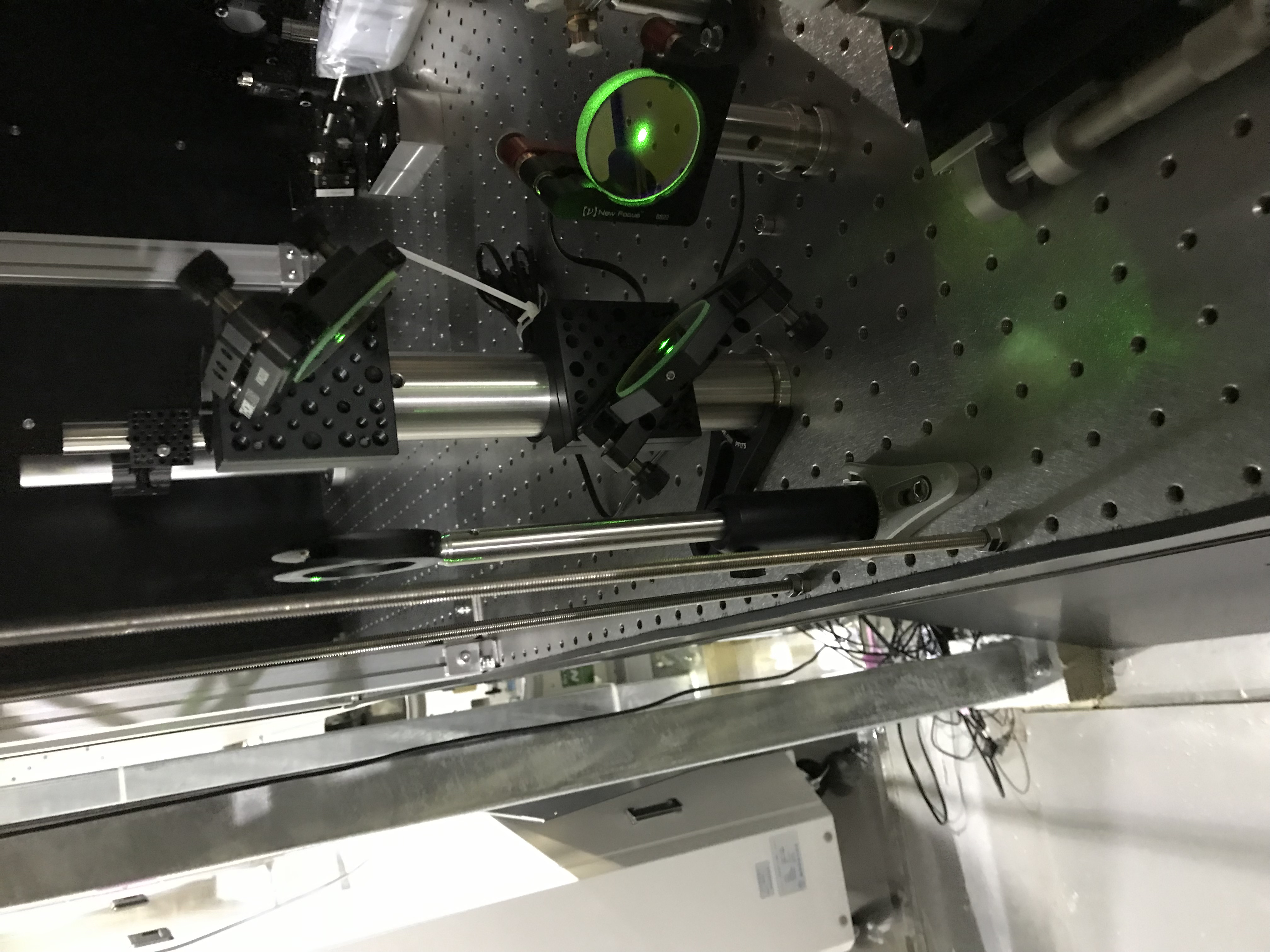
Of the POP cover, there was yet another black wall remaining at the side of the PR2 chamber. I firstly dismantled this wall to widen the workspace (Figs. 1, 2, and 3). To access the periscope or relocate it, this wall must be detached definitely.
About the motivation for the periscope relocation, read the previous report (17154). The first and the most important step is to preserve an optical axis that I want to recover after the relocation. Indeed, I want to recover the optical axis that connects the upper periscope mirror via the viewport window to POP-POM (and to the center of the PR2 mirror as well). In the real work, I tried to preserve the optical axis from the upper periscope mirror to the viewport window. Let me say that differently; I want to realize this optical axis from the upstream optical axis; "the upstream optical axis" means the one starts from HBS and go in the direction that is determined by the incident angle to the HBS and the HBS's tilt angle. These two parameters, i.e. the incident angle to the HBS and the HBS's tilt angle must not be touched this time, as I'd like to keep this optical axis while relocating the periscope. In the first look, it seemed the two optical axes that I wanted to connect with the persicope to be relocated were twisted each other (nejire no ichi), so one could have estimated this work would be hard.
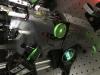
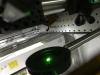
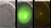
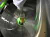
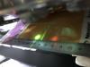
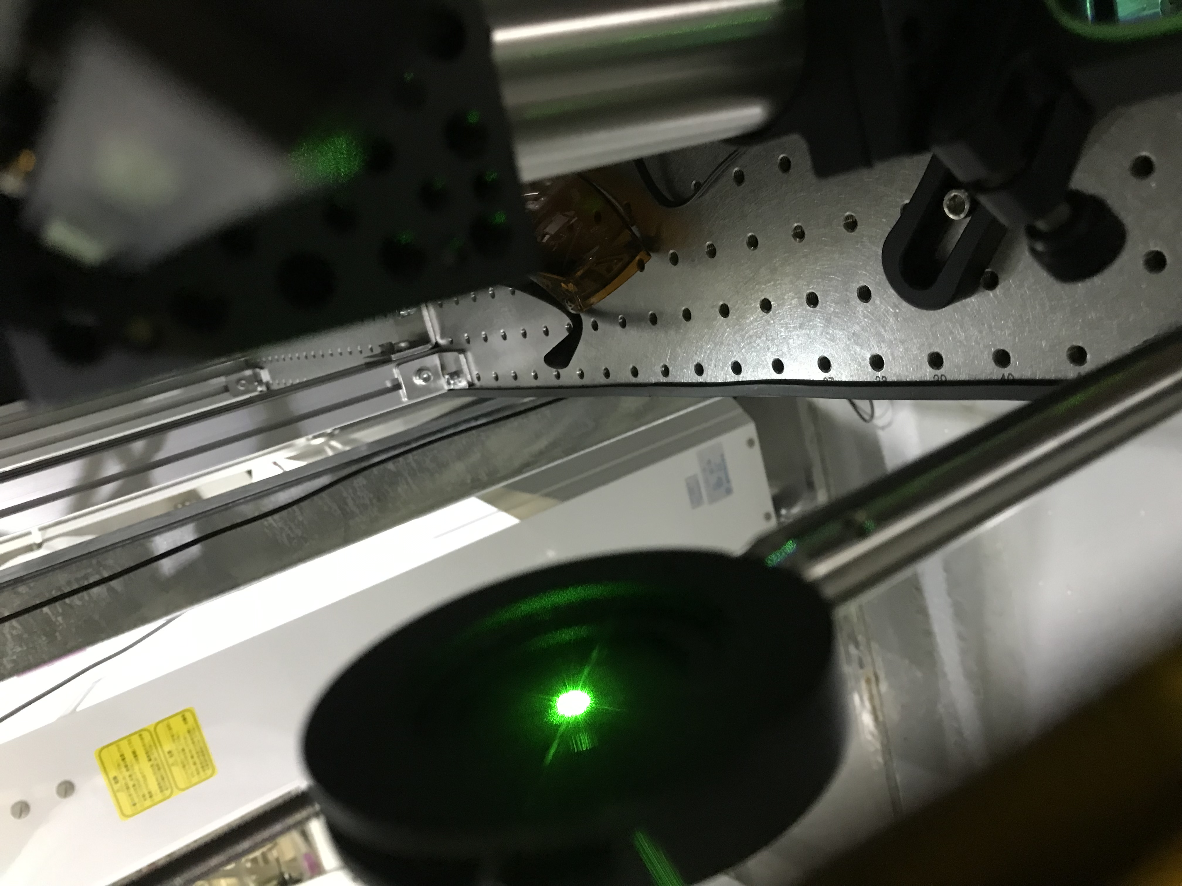
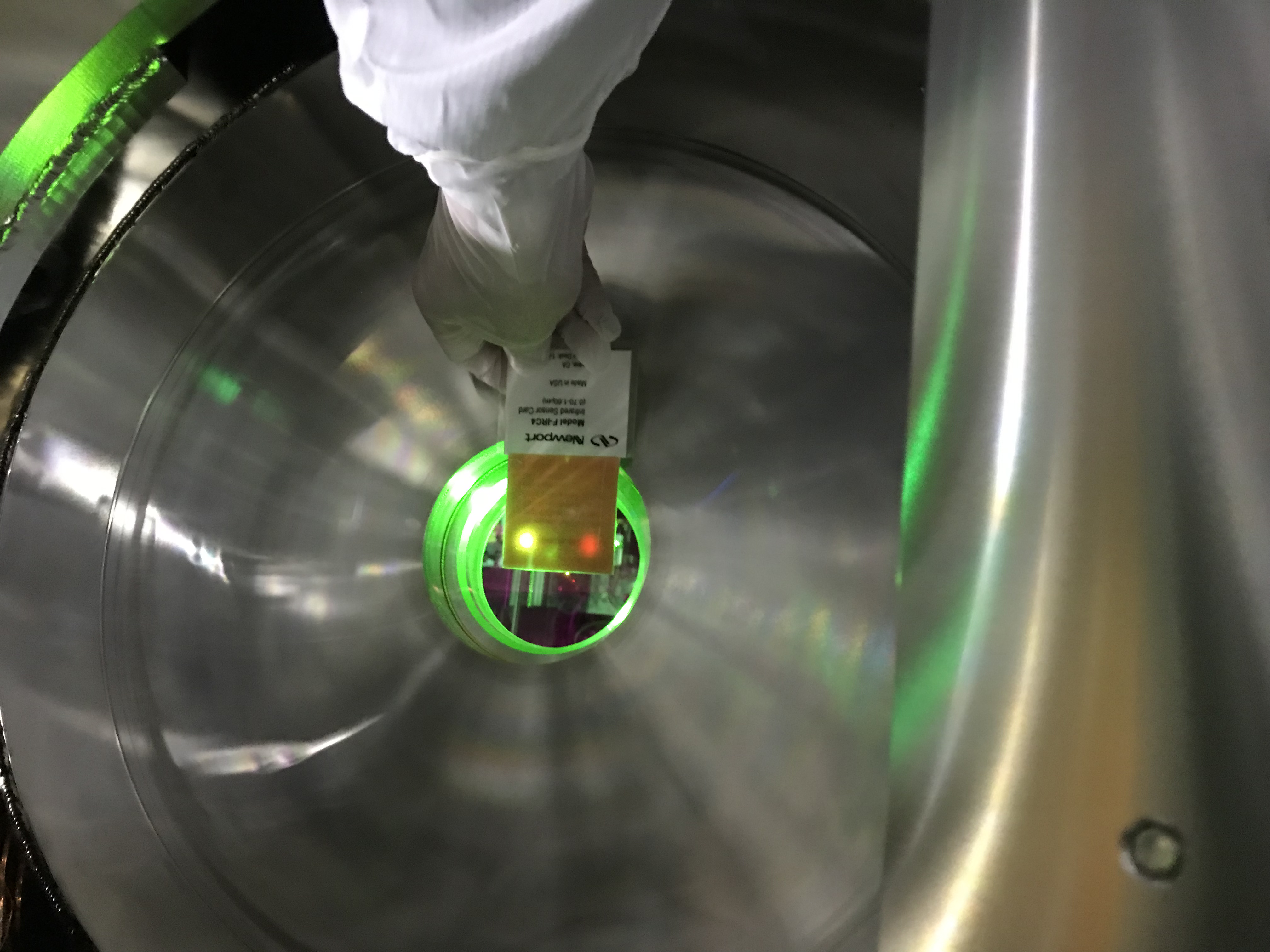
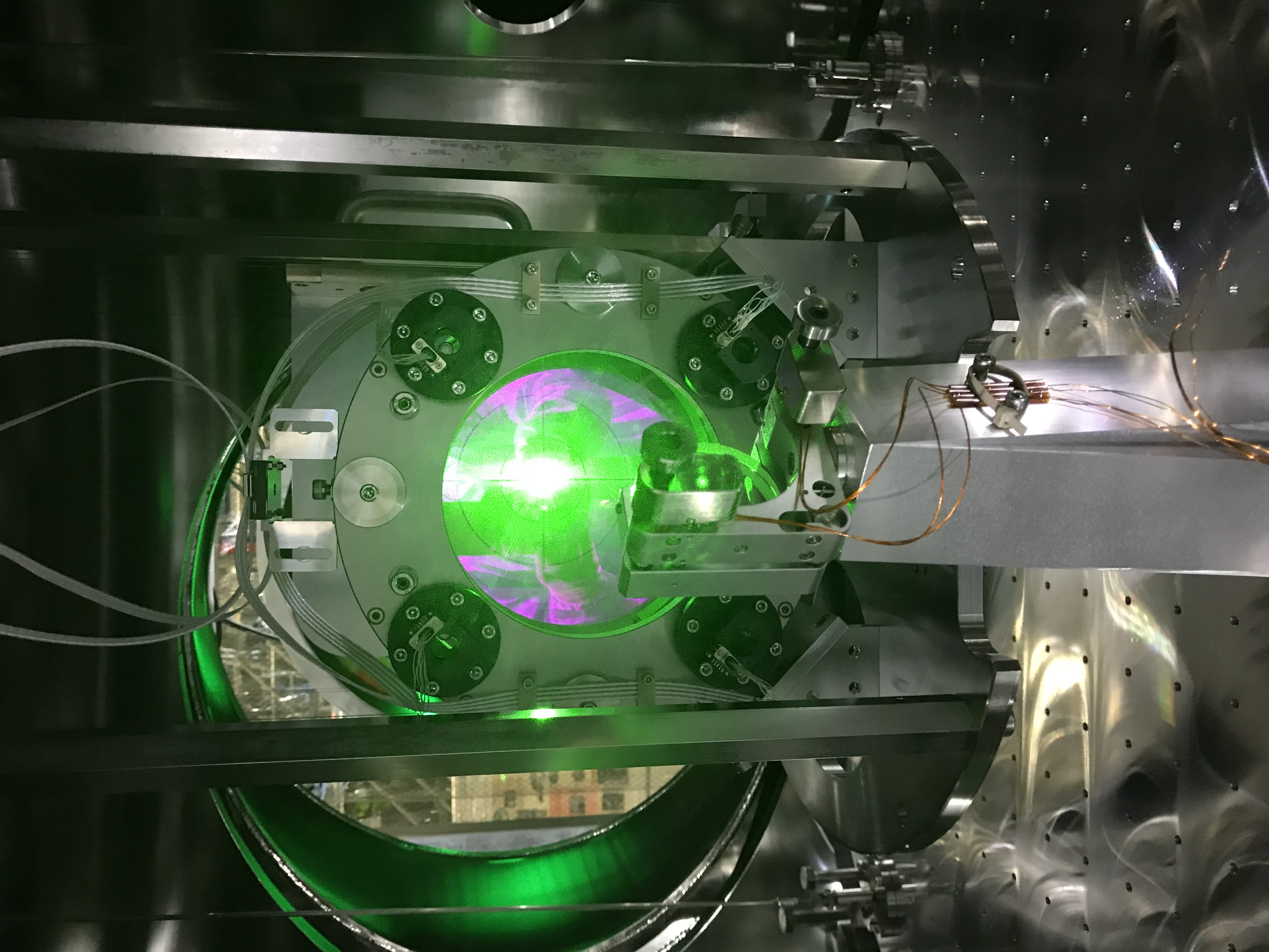
As considered in 17154, I put an iris diaphragm in front of the upper periscope mirror and match the hole to the green beam (Figs. 4 and 5). Also, I put a cover on the viewport window and marked a point at which the green beam penetrated (Fig. 6). The photos taken without any ND filters (actually I used laser safety goggles OD2 or OD4 or their combination as such filters) show saturated green spots. With appropriate filters in front of my smartphone camera, the saturation or halation seems reduced.
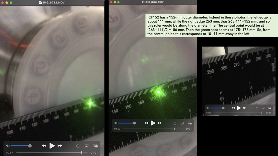
By the way, the green spot is at 10~11 mm off-centered in the left (-X direction) as roughly analyzed in Fig. 7. Let us compare this number with the "design" described in 17154, which says the green spot would come 14 mm off-centered left from the center point (26+24+30=80mm diameter effective area is assumed, so the center is at 40 mm, and 40-26=14 mm). So will the 4-mm difference be something??? Note that the designed number can vary if I choose a different steering angle for POP-POM in LightTools.... in other words, I may be able to prepare another "design" that would have this 10-11 mm off-centered version. Anyway, I can say the beam spot is close to the designed position.
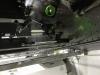
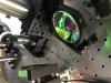
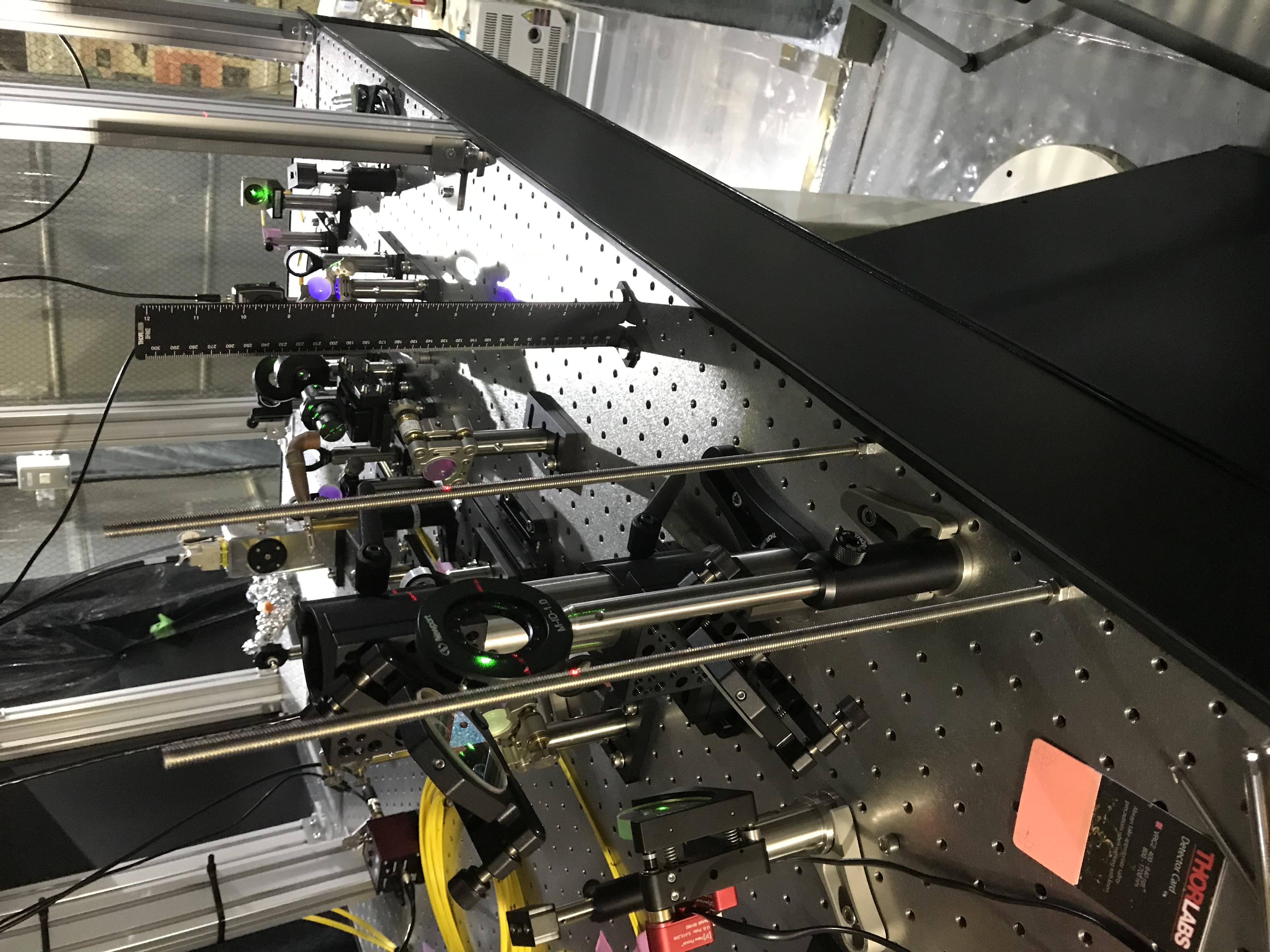
Then, I detached the periscope, and modified the periscope system like a mirror-symmetric one. And somehow relocated the persicope (Figs. 8 and 9) so that
- the resultant green beam can pass through the iris diaphragm and shoot the mark on the viewport cover,
- the adjusters on the mirror holders have appropriate range remaining,
- the green beam spots on the periscope mirrors are not close too much to the mirror edges; remember PR2_TRANS_BACKWARD (4.5 mm radius, in IR) will come on the same optical path with this green, and
- the free space in the +X side of the periscope becomes as wide as possible so that another periscope for PR2_TRANS_FORWARD will be able to come there.
I do not want to repeat this again... a nightmare like jambow-manbow, but there is still a theory of simple geometric optics behind. Use your brain!
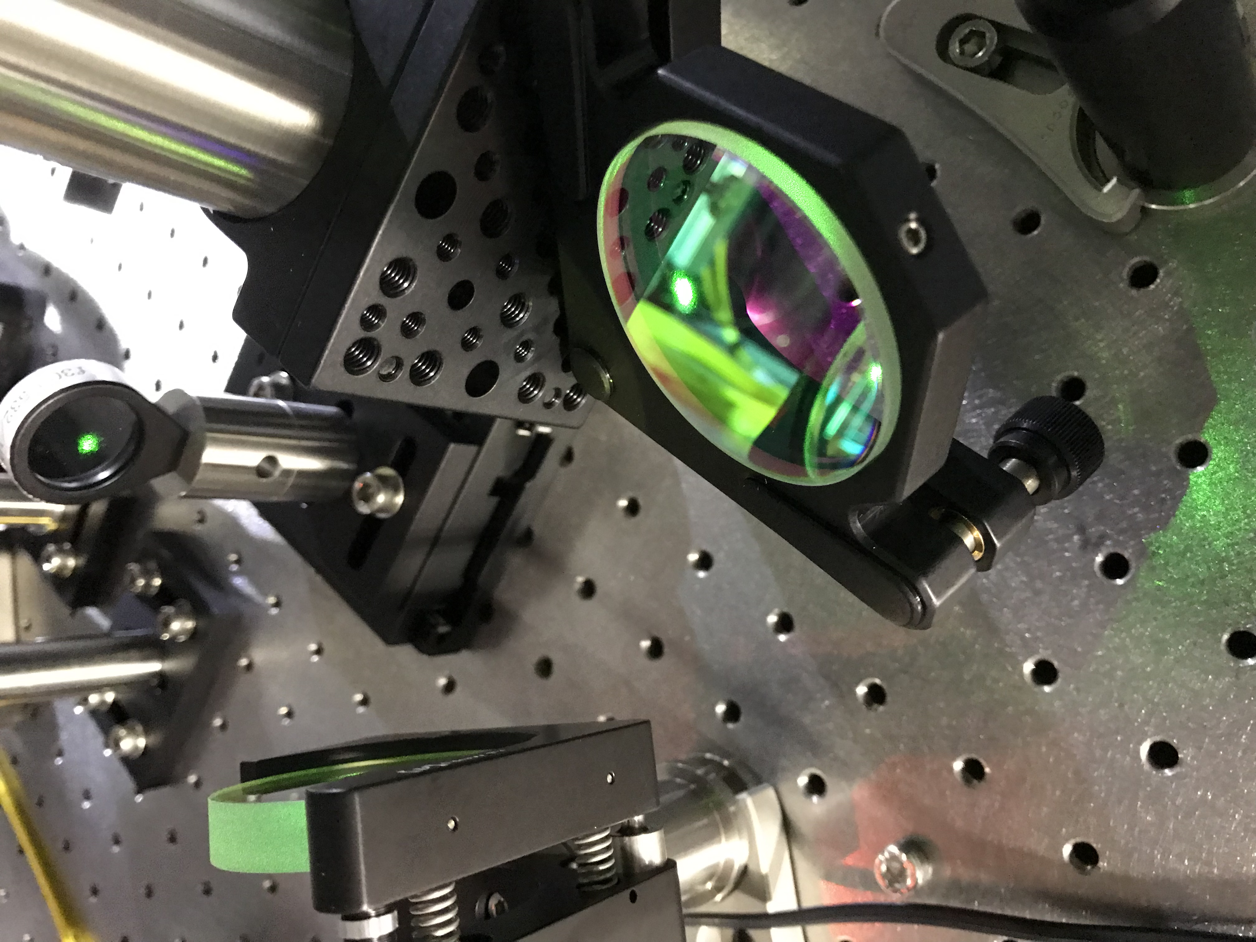
Then, thanks to my luck and efforts, the green beam came back to very close to the one before relocating the periscope. The green beam went thourgh the viewport window and illuminated POP-POM, and the following beam reflected at POP-POM shoot close at the PR2 HR target center. So I tweaked HBS in pitch and yaw to let the beam spot come at the PR2 HR target center (Fig. 10).
Sending GrX to the PR3 center
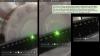
Firsly at PR2, I actuated the picomotors on POP-POM with a joystick to guide the green beam to the PR3 center; there has been a target plate as well (17140) by Hirata-san and Yano-san. It is about 11 m away from PR2 to PR3 (see here), so I went to PR3 to see the acutual situation. Then I learned the spot tweaking needed to be more precisely; it was displaced particularly in yaw (again, note that, for these precise beam spot centering, the ND filters were essential; saturated beam spot would be mis-understanding). So I contacted Ikeda-san and asked him to tweak the picomotors from MEDM (17165). See Fig. 11.
Coming back to the PR2 area, I checked several other points. For example, the locations of the IR (PR2_TRANS_FORWARD) and the green beam in the PR2 chamber (Fig. 12). Again, due to high power of green, it was difficult to check the situation on POP-POM. Later check it. The beam separation just out of the viewport window (i.e. in air) is shown in Fig. 13 ;99-71 = 28 mm separation, while the "design" in 17154 says 24 mm. Hmm... 28/24 = 1.16 times larger angle?? Let's see. When we will take the full alignment of the interferometer, these difference might change... (Revisting this: in the "design" I forgot some thinckness of the K400 flange (25 mm), the viewport assembly (36 mm; see here), plus the distance from the viewport window to the sensor card (say, 40 mm). Then at this point (25+36+40 ~ 100 mm away), the separation is calculated as 26 mm (I think this 2 mm increase is consistent with the additonal distance of 100 mm, as the incident angle of the main beam to PR2 is about 0.68 deg according here, so the two beams would separate twice of this, meaning 0.68*2*pi/180 = 0.02 rad, or 2mm/100mm; thanks you for suggesting this rough estimation last night, Enomoto-kun), which might be within error of 28 mm measurment; is that a little arbitrary??)
Finally, got back the PR2 target, and checked again the green beam centered (Figs. 14 and 15).
Next step
Tweak PR3 to send the green light to BS, IXA, IXC, and...
Notes
The periscope mirrors would be still PYD-20. There were bright green transmission beams from behind these mirrors. These mirrors will/must be replaced with more appropriate ones in the future...

