Cont'd from 16946; K. Tanaka, R. Takahashi, Hirata, Yano, Akutsu
Abstract
The main beam reached PR2. Although IFI does not yet get back onto the beam axis, now we can say it is confirmed that the IMMT2 center comes roughly on the line connecting the centers of PRM and PR2; thanks to the careful preparations so far (like 15799) plus luck, no iterations of IMMT2 relocation to achieve this today.
Preparation
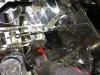
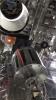
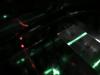
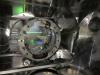
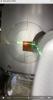
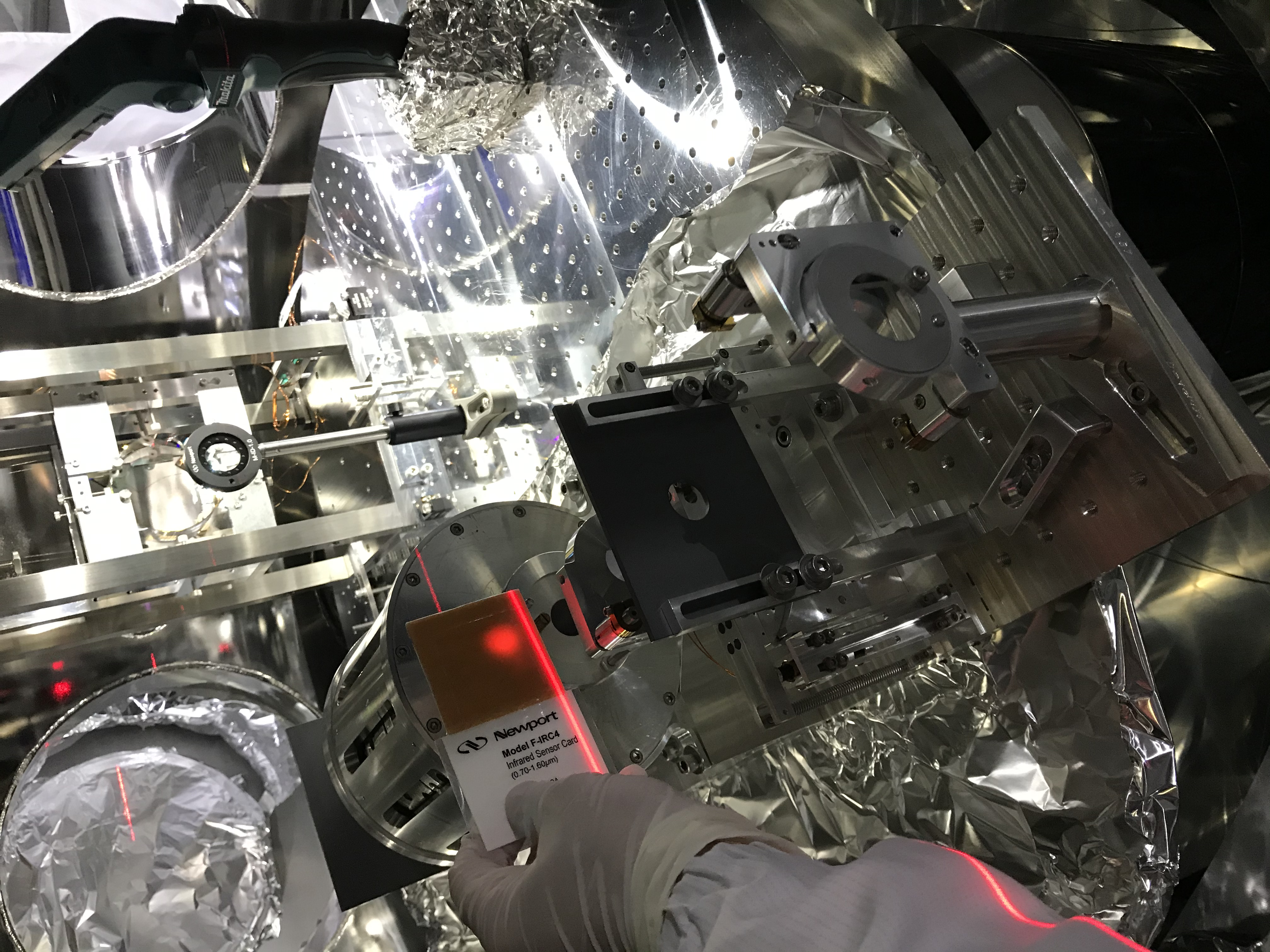
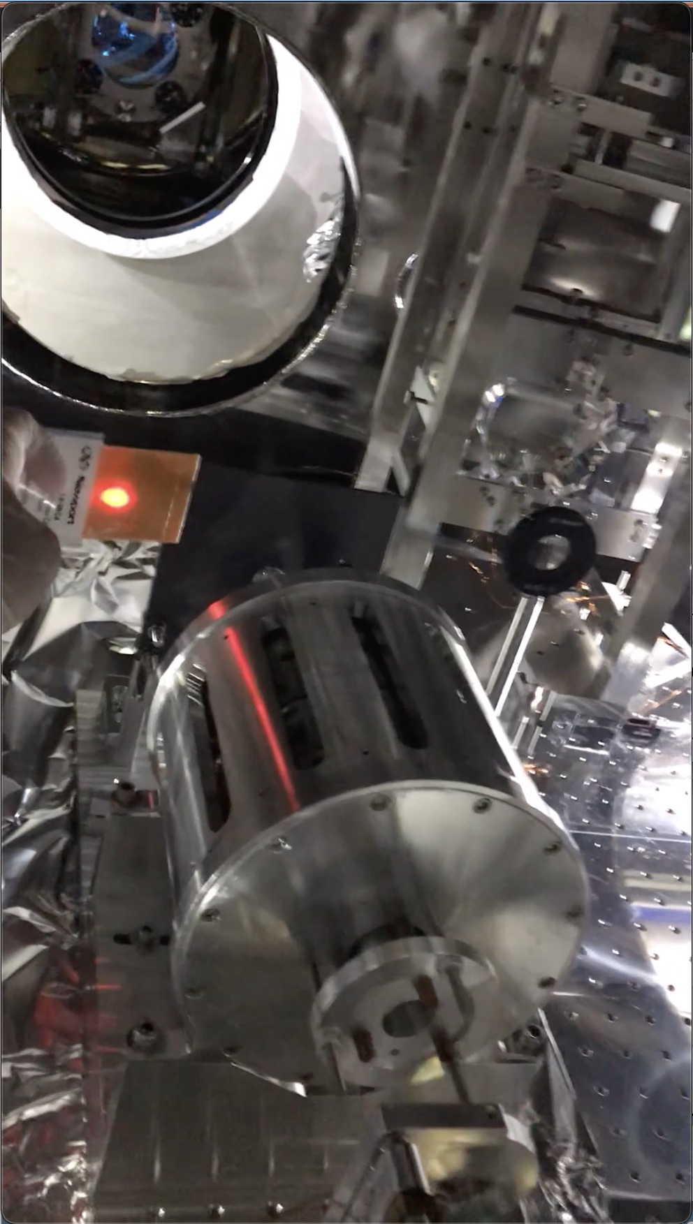
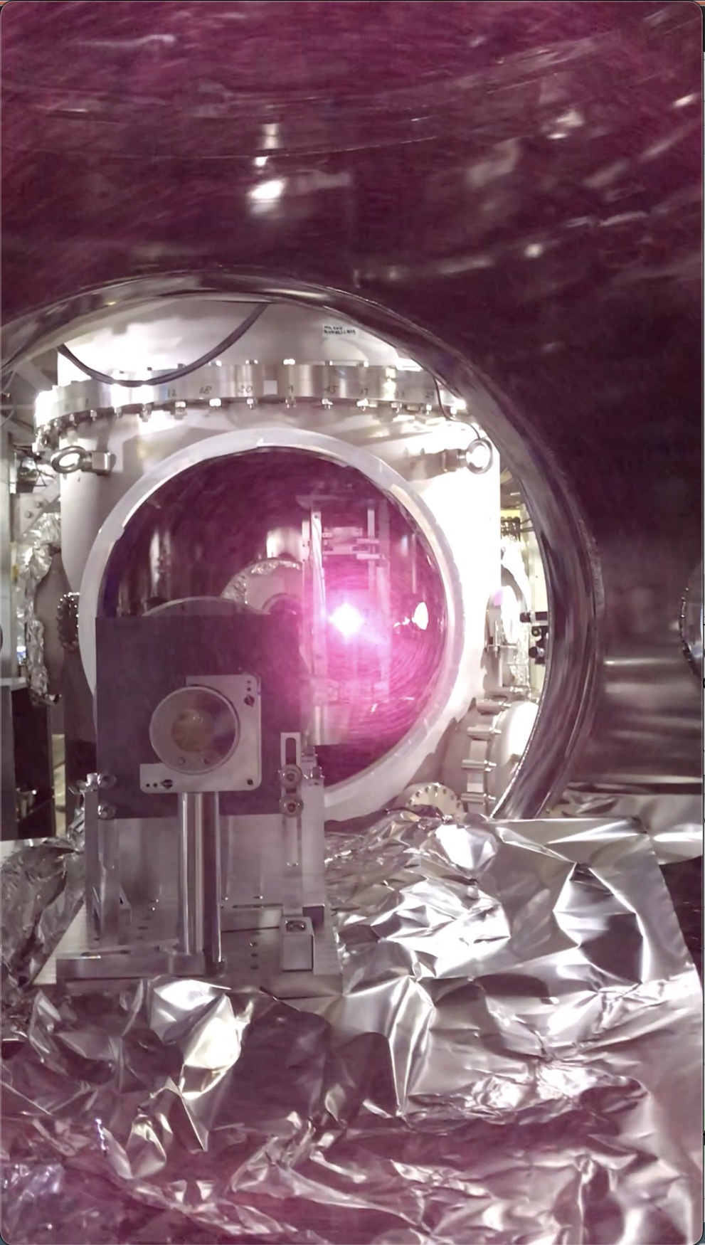
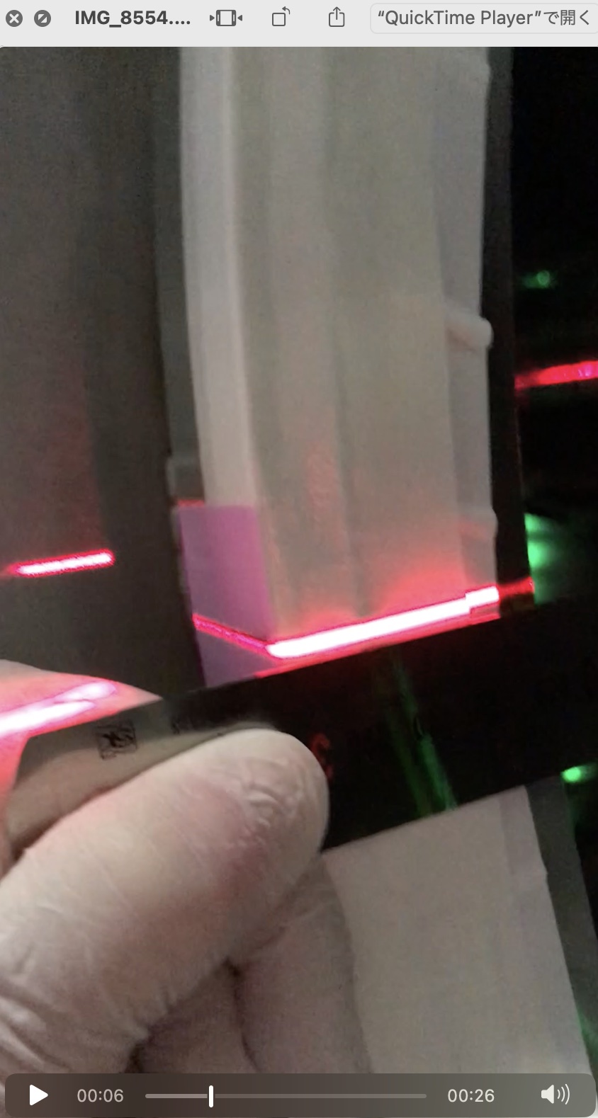
Unfortunately the IFI that had been tentatively put in the IMM chamber cliped the beam from IMMT2 (Fig. 1). So, I moved it slightly within the IMM chamber to open the way for the beam (Figs. 2 and 3); luckily, enough with my hands to move.
Tweaking IMMT2 refering the beam spot on PR2
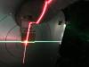
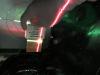
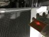
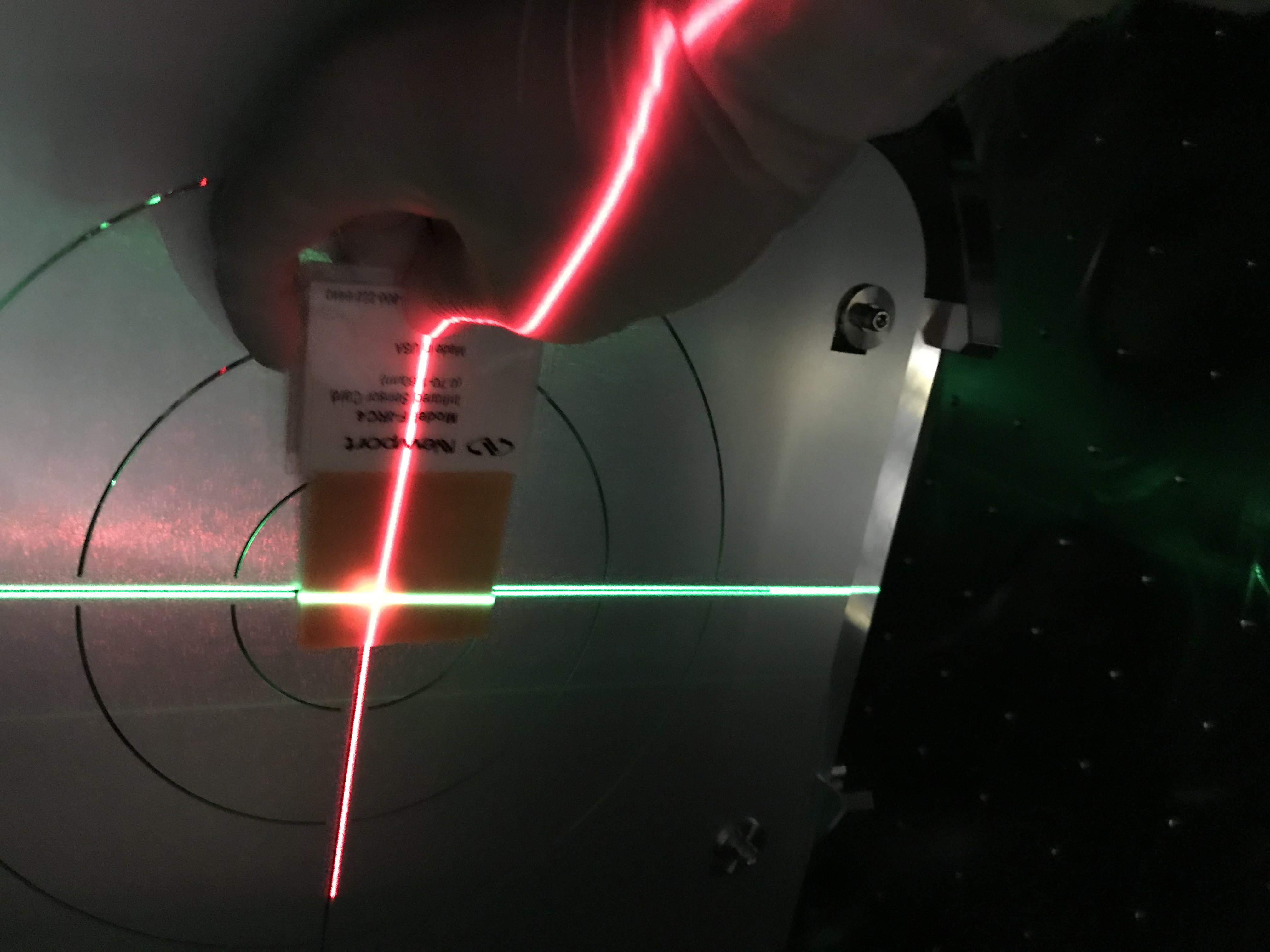
Hirata-san and Yano-san had set the new beam target at PR2 HR already (see 16925 and 16945). Refering the target, we tweaked IMMT2 to align the input beam to the center of the target (hoping the target center is mostly coincidence with the center of PR2; such precise confirmation will be done after re-installation of IFI). See Figs. 4 and 5; note that there should be 1/300 rising of the beam, but may not be apparent only with these two photos. By the way, I learned that even though the target has marker slits (to show the "center" for example), laser levels must be used to illuminate the reference slit lines so that one can easily avoid a trap of parallax!
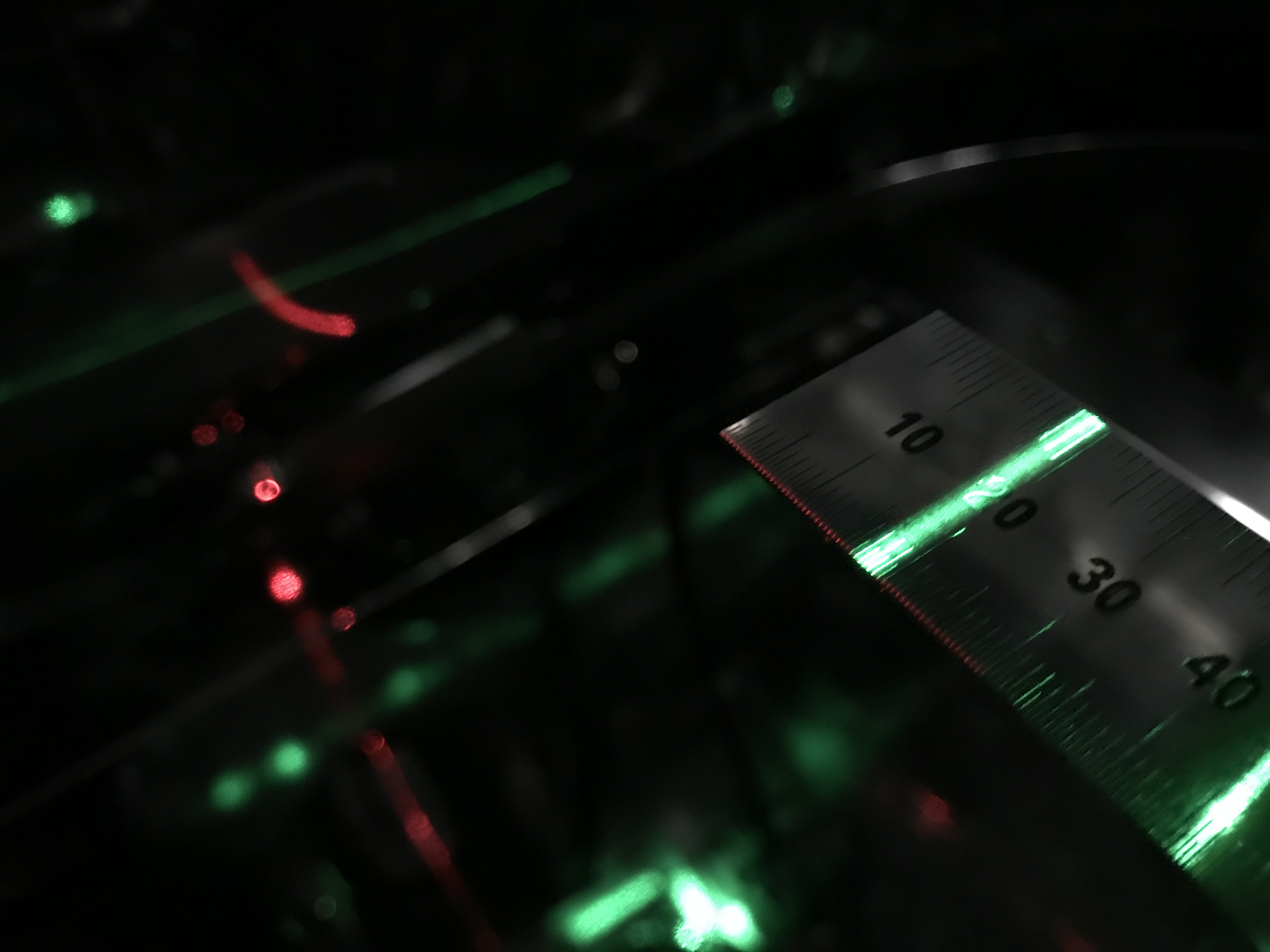
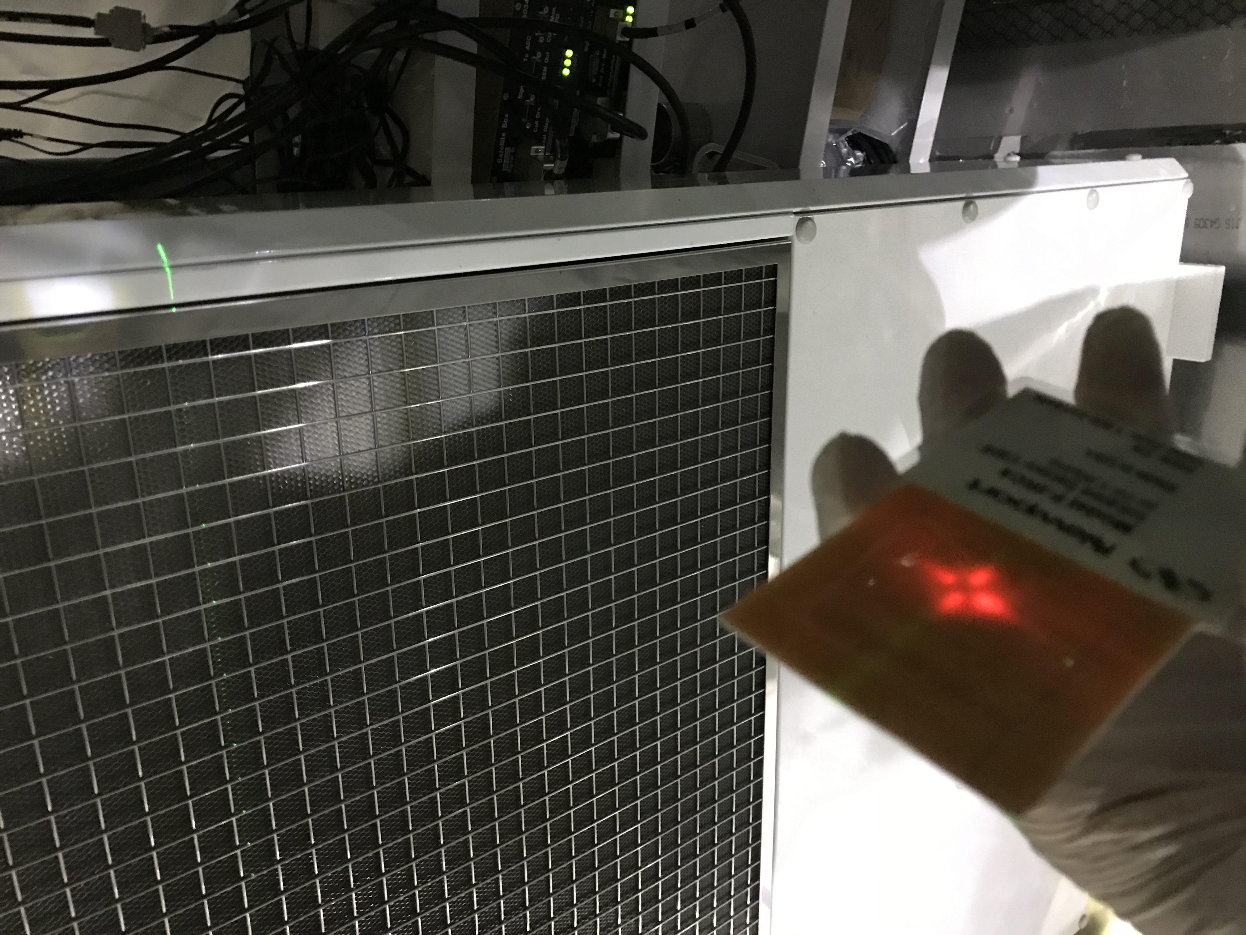
As Hirata-san made a detailed post (16956), the following is how to find the "right" vertical cross section drawn by this green vertical beam, as far as I got, in my words. There is a pair of scratch lines on the recoil mass to indicate a center reference in the horizontal direction, and this is the case for both PR2 and PRM. Refering the scratch lines, and using the green laser level that can provide vertical lines in the oppoosite directions, they illuminated the scratch lines on PR2 and PRM with a green laser level at the same time to have the green beam can connect the centers of PR2 and PRM (of cource, precisely speaking, these scrathes are for the recoil mass center, not the mirror itself... but it may be nice to think of the fact that the aperture of the recoil mass detemines the "effective mirror area" for the KAGRA case.) Precisely speaking, according to them, each recoil mass got roll displacement to some extent; however this is not a critical problem, as they could somehow take the roll into account by comparing between the higher and lower displacement of the scratch lines with respect to the green vertical beam. By the way, the nominal distance between PRM and PR2 is, according to the wiki, about 14.8 m. The laser level would have a few mm error to illuminate stffus in this distance, so the results need to be cared. I roughly measured the horizontal position of the vertical green line at the -X flange of the PR2 chamber, and it was about 282 mm from the +Y edge of this flange (see Figs. 6 and 7; 300-18=282mm; my brute method was explained in 16946 ). This is consistent with a number (281.5~283.2) in my rough cheat sheet (to be made soon, hopefully). Nice work!!!
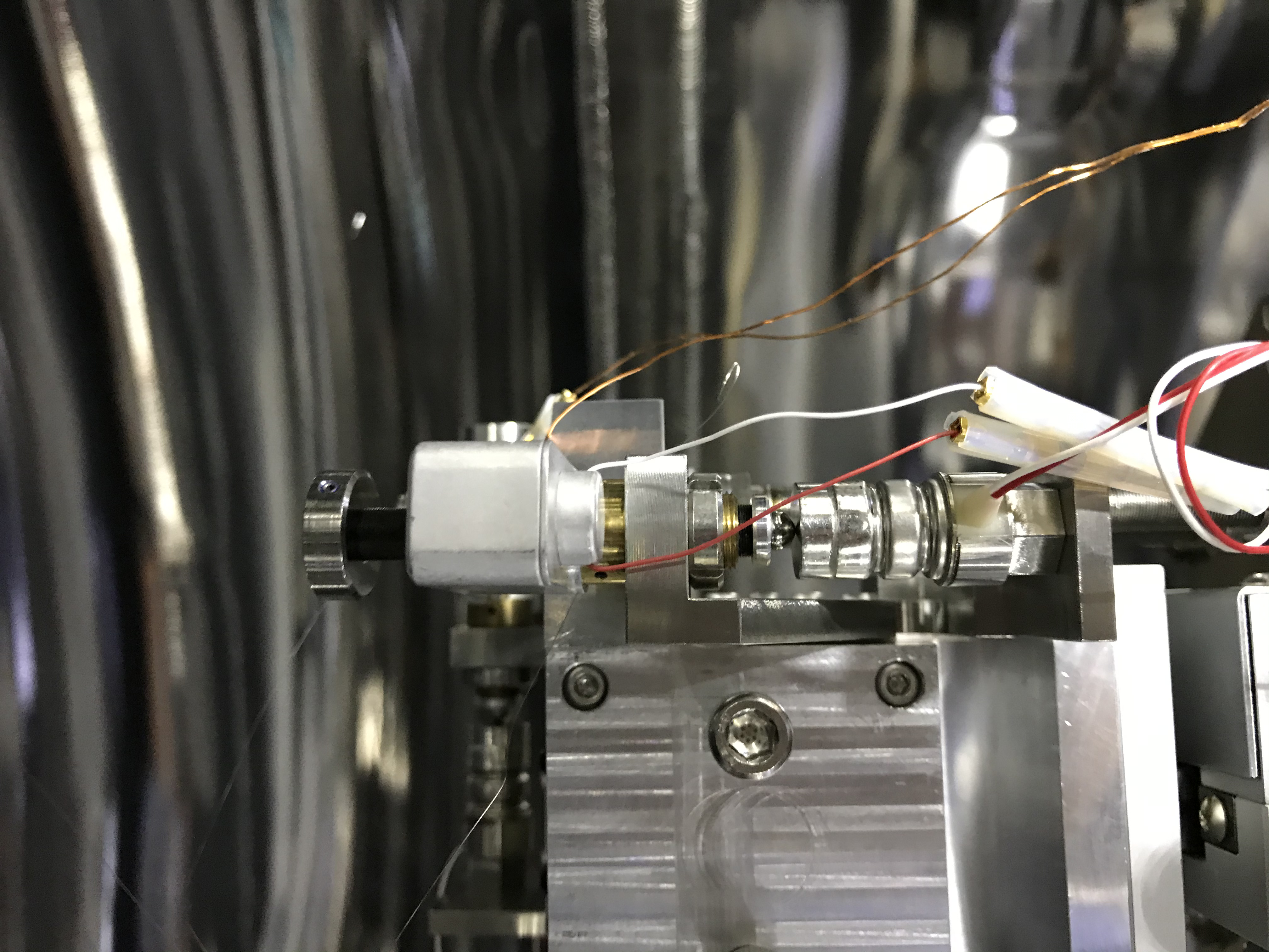
While Takahashi-san tweaked the IMMT2, I monitored the IR beam spot on the PR2 target, and communicated with PHS each other. For pitch, Takahashi-san used the dedicated picomotor. As we were worried, this reduced the remaining picomotor range, but as also we expected, the required amount was so small that it was hard to say the consumed stroke (Fig. 8). For yaw, Takahashi-san used the dedicacted picomotor as well: not the positioners for the base plate of the IMMT2 suspension cage. Luckly, the yaw picomotor needed to go in the nicer direction that increased the range! So we did not off-load the yaw picomotor range at all, as of today; unlike MCo, IMMT2 is not a cavity mirror. Hard to access and take photos of the yaw picture. Later, after re-insallting IFI and done everything, we might revisit here.
Ok, now (I believe) we align the IR beam to connect the centers of IMMT2 and PRM. Let's check if the PRM center would be on this line or not.
Confirming the PRM center on the main beam
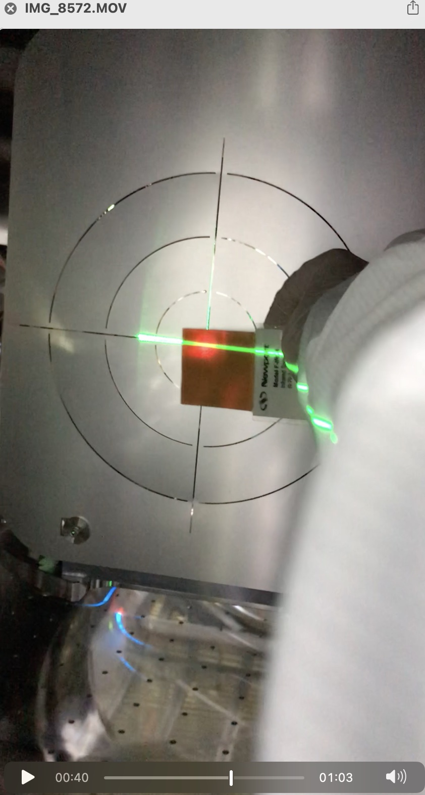
We set another new target at PRM AR. For this work, we used the green vertical beam from the one left in front of PR2 to illumate the PRM HR (and its recoil mass), and we set the target at PRM AR referring to this in the vertical direction (Fig. 9). The central vertical slit on the target could let a part of this green laser go through to PRM AR, and we could use this through light as a reference line. This is useful as this also containes the wedge (about 2 deg) effect; in our context, the difference of the index of refraction at 532 and 1064 nm for SiO2 is in the 2nd digit (see for example here), and I only would like to use this reference near the PRM AR surface, so I did not care so much. For pitch reference, we copied a height reference at PRM HR side to AR side with another green laser level, and used it. The view at PRM HR is shown in Fig. 10. We could say the reference and the beam matched each other sufficiently, so we stopped at this point.
I took a photo at PRM HR and it is Fig. 11 showing a transmitting beam through the target set at the PRM AR. Interesting. Due to the slits, the beam got modified accordinngly, and you might able to see carefully the crossing green laser lines.
Ok, relieved. Doing more will be after re-installing IFI.


