Cont'd from 16920.
R. Takahashi, K. Tanaka, Akutsu + Yano, Hirata; Takahashi-san's report is 16944, and Hirata-san's report is 16945.
Abstract
Took rough initial alignment of the input beam from STM1 to IMMT2. Now the beam reaches IMMT2, although we have not yet got back IFI.
Moving the IMMT2 suspension cage
As reported in 16920, we had set positioners and mechanical guide parts around the base plate of the IMMT2 suspension cage. As discussed in 15799 and reported here, in order to align the IMMT2 center onto the line that penetrates the centers of PRM and PR2, the IMMT2 should move aboout 7.6 mm in -Y-ish direction. Actually, there is another "nominal" displacement value; this is based on the nominal position of IMMT2 (base on my ray trace in which every mirror is located at a coordinate coming from the original Aso-san's calculation with gtrace) and a footprint of the IMMT2 suspension cage, and it says the displacement should be about 18 mm, (summarized in the Sato-san's mirror_position_immt12.pdf, which should be uploaded anywhere). We do not know which is suitable with the real world now. One hint might be that the suspension has also a piccomotor that can move the whole suspended stuffs in horizontal direction, so the footprint might not be useful as a mechanical reference any more (in principle). However I suspect that the amount of pico-moving (if any) won't explain this ~10mm difference of the "nominal" values.
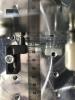
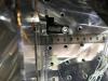
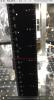
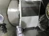
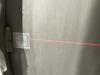
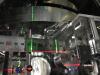
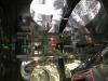
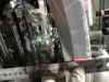
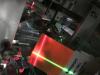
Anyway, as the stroke of each positioner was not so long as 17 mm, we started with 7.6 mm move. First I scratched a line on the top surface of the optical table along with the +X-side edge of the cage's base plate with a scribble needle (Fig. 1). Then rotateing pushing screws in the two positioners, Takahashi-san pushed the IMMT2 cage. The resultant move amount includes a certain error bars, but we could say it was around 7.6 mm (Figs. 2 and 3). We did not feel needs of further precise work, so we stopped here.
Is the IMM optical table set 3-4 mm higher?
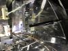
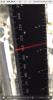
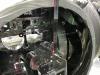
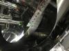
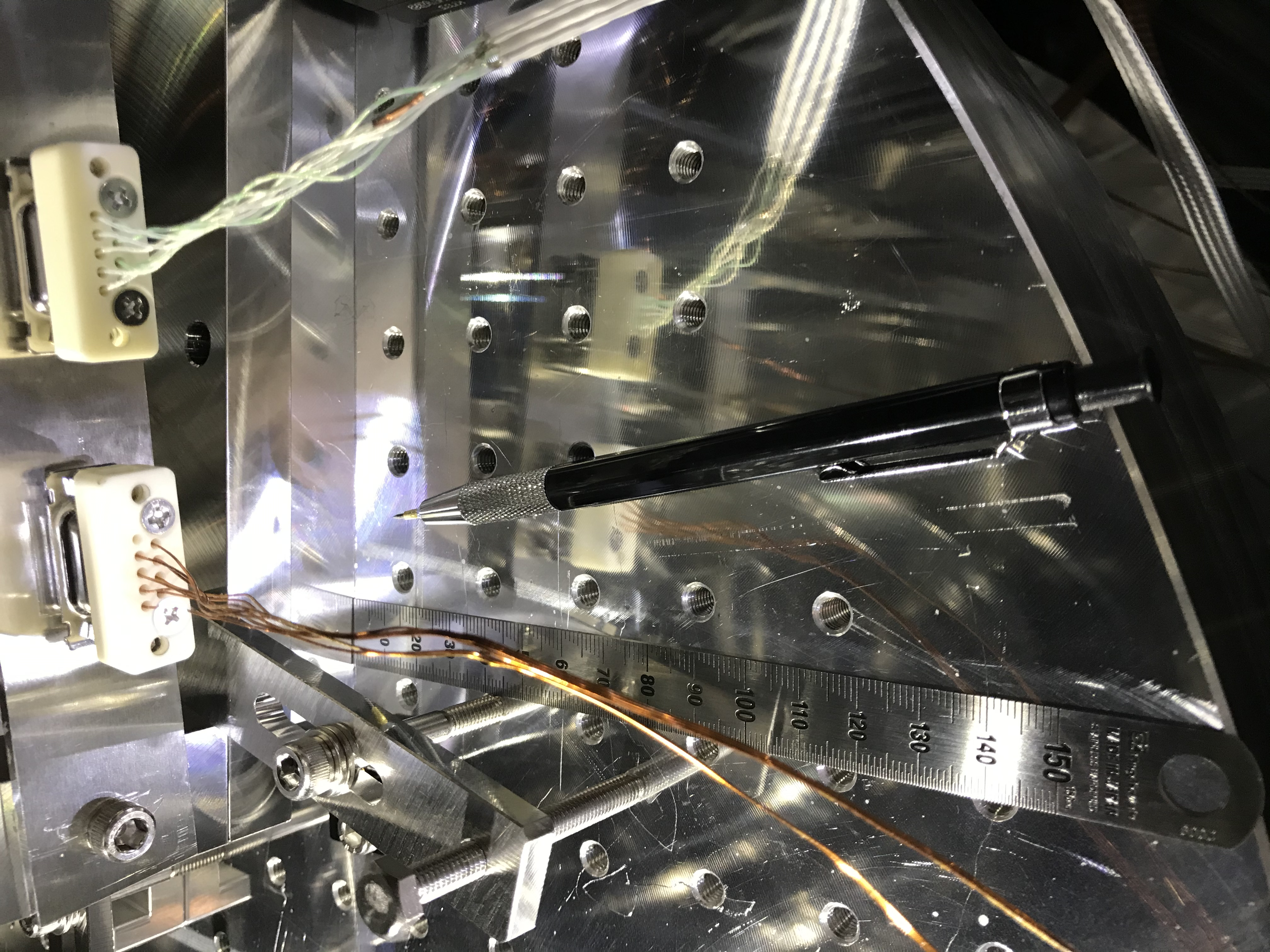
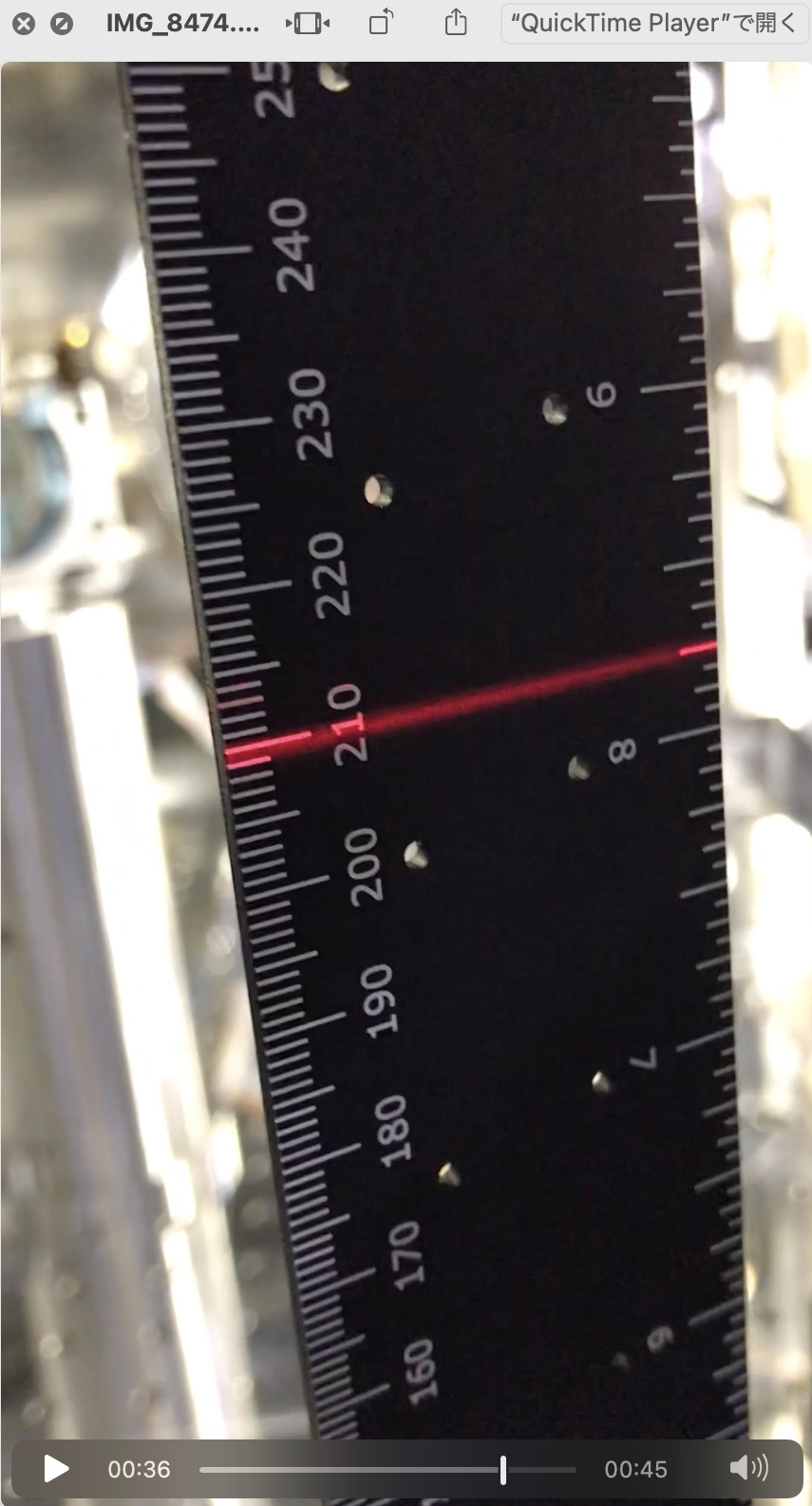
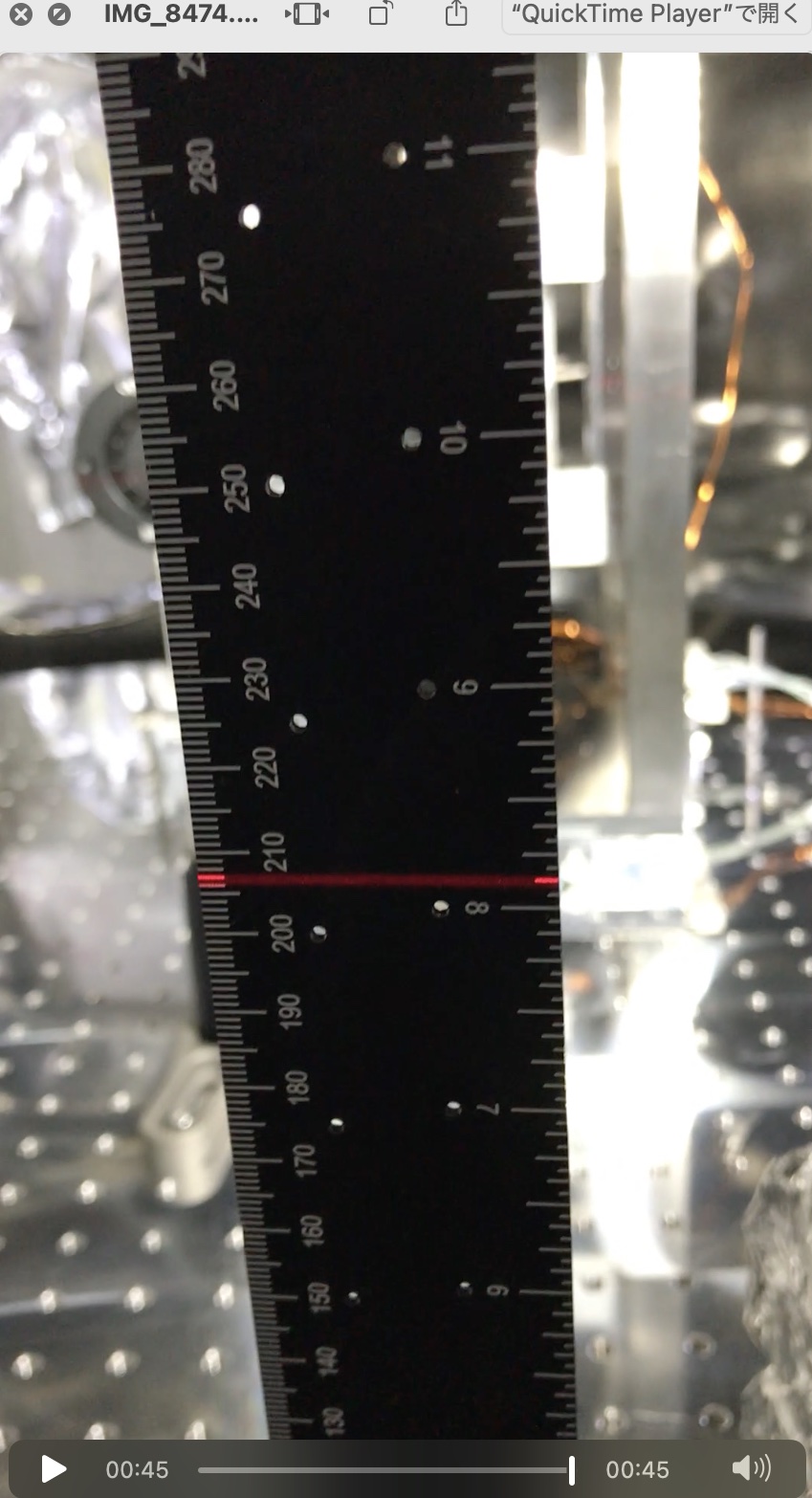
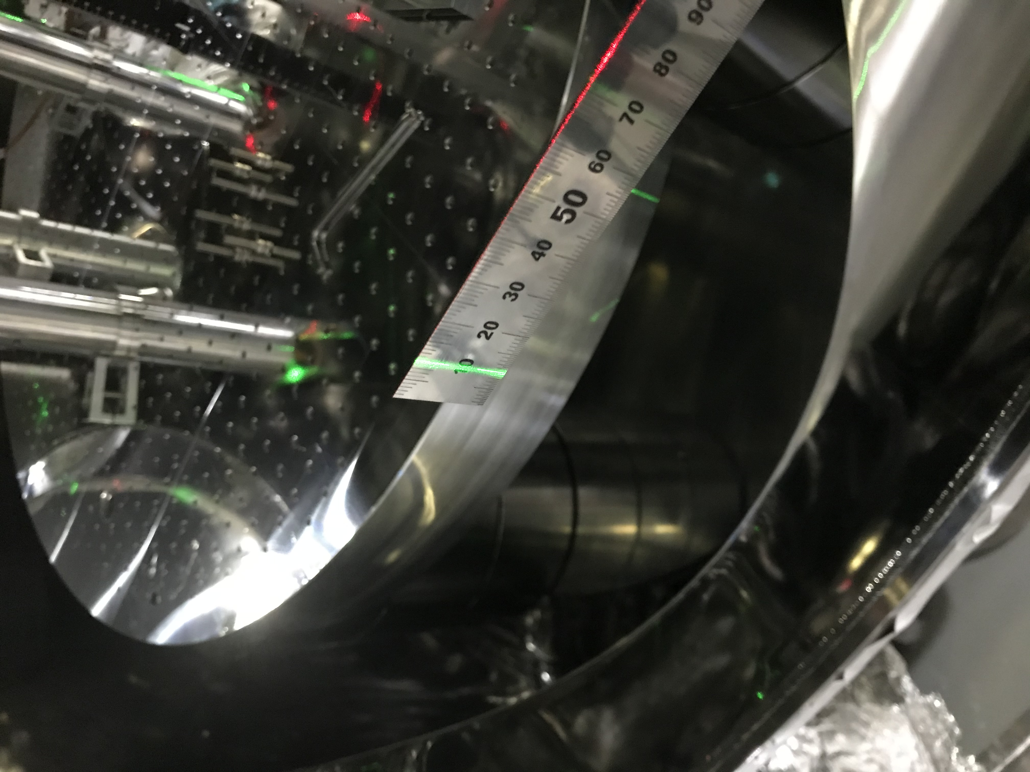
Here we made the following measurements after all this time. With a laser level, illuminated each vertical ruler set on each optical table in the IMM or IFI chamber. When the laser level illuminated 210 mm in the IFI chamber, it was 207 mm in the IMM chamber. See Figs. 4 and 5 for IFI and IMM, respectively. OMG! I should have measured this.... Did the same for each markers found at each side of the IMM oor IFI chamber, the difference was aboout 4 mm (Figs. 6 and 7), while these have to be the same in design. There would be several theories for explaining this inconsistency. One hint will be introduced soon later in this post, and that would suggest that the optical table in the IMM chamber is higher 3 mm than the nominal. Or one might be able to say that the center height of the -X flange of the IMM chamber is 3 mm higher than the design.
Today we determined our mind to go leave this as is (also rapidly discussed with Aso-san on call), and to input the IR beam at the 3-mm higher spot on IMMT1. IMMT1 RoC is -8.9m according to the wiki, and the 3 mm shift can be compensated by tiliting IMMT1 3mm/8.9m = 0.3 mrad. Considering the distance between IMMT1 and IMMT2 is about 3 m (see wiki), this only makes 1 mm difference on IMMT2. Considering the beam size on IMMT2 (abour 4.5 mm; see wiki), it is hard to distinguish with a sensor card. So we ignore this 3-mm difference today. Yesterday we confirmed how to lift up the IMMT1 cage to replace the base plate, we may be able to do, if necessary, later.
Beam alignment STM1 to STM2
With the laser level horizontal mark (210 mm height on the IFI optical table), we aligned STM1 so that the reflected beam from STM1 illuminated the vertical center of STM2 by tweaking pitch adjuster of the STM1 holder. For yaw, according to the ray trace mentioned above the designed spot poosition on STM2 should be about 1.7 mm (in -Y) horizontally away from the center of STM2, but today I did not care so much. It seemed around center. Let's do more precise things, if actually required, after IFI got back.
Beam alignment STM2 to IMMT1
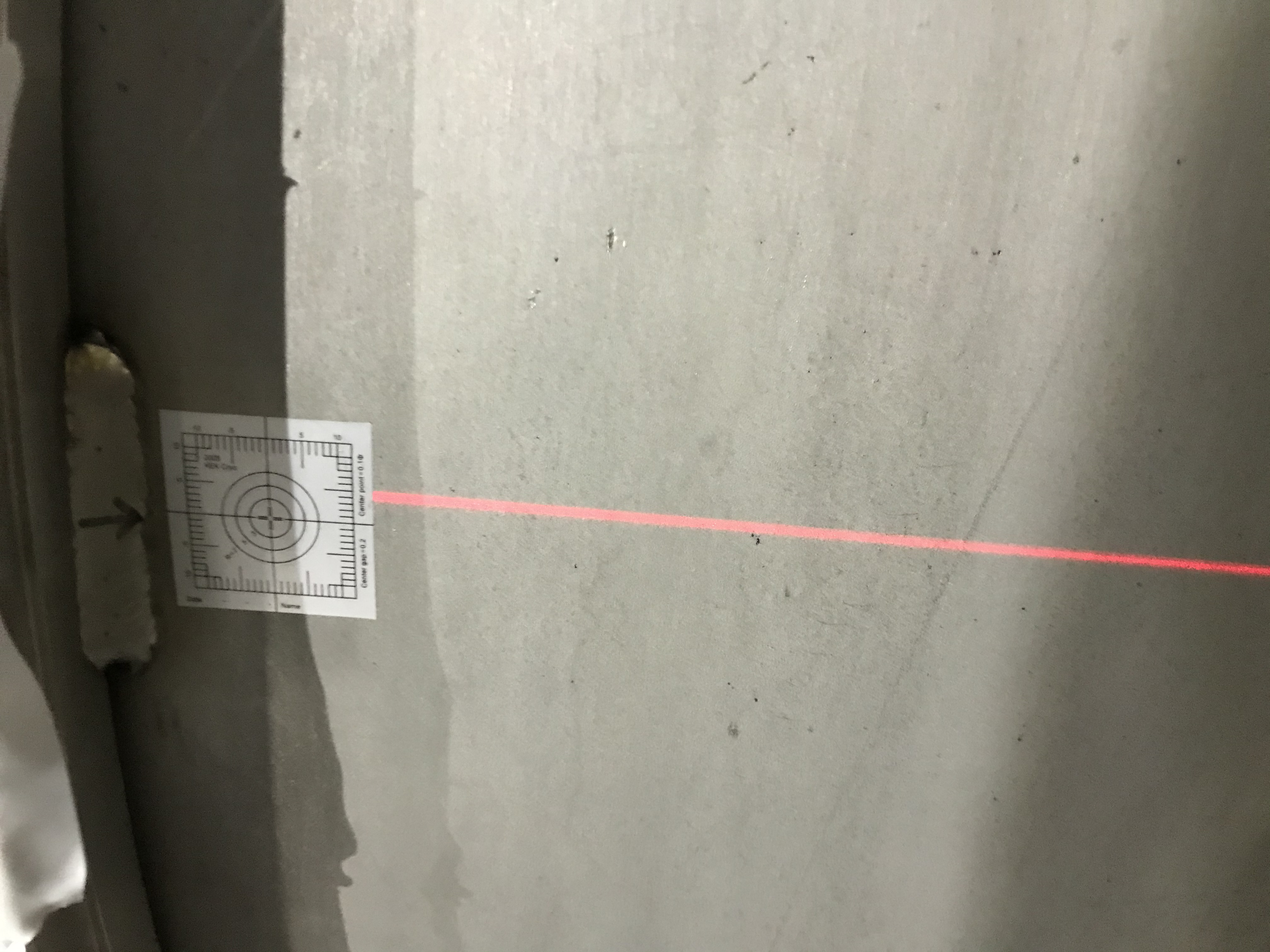
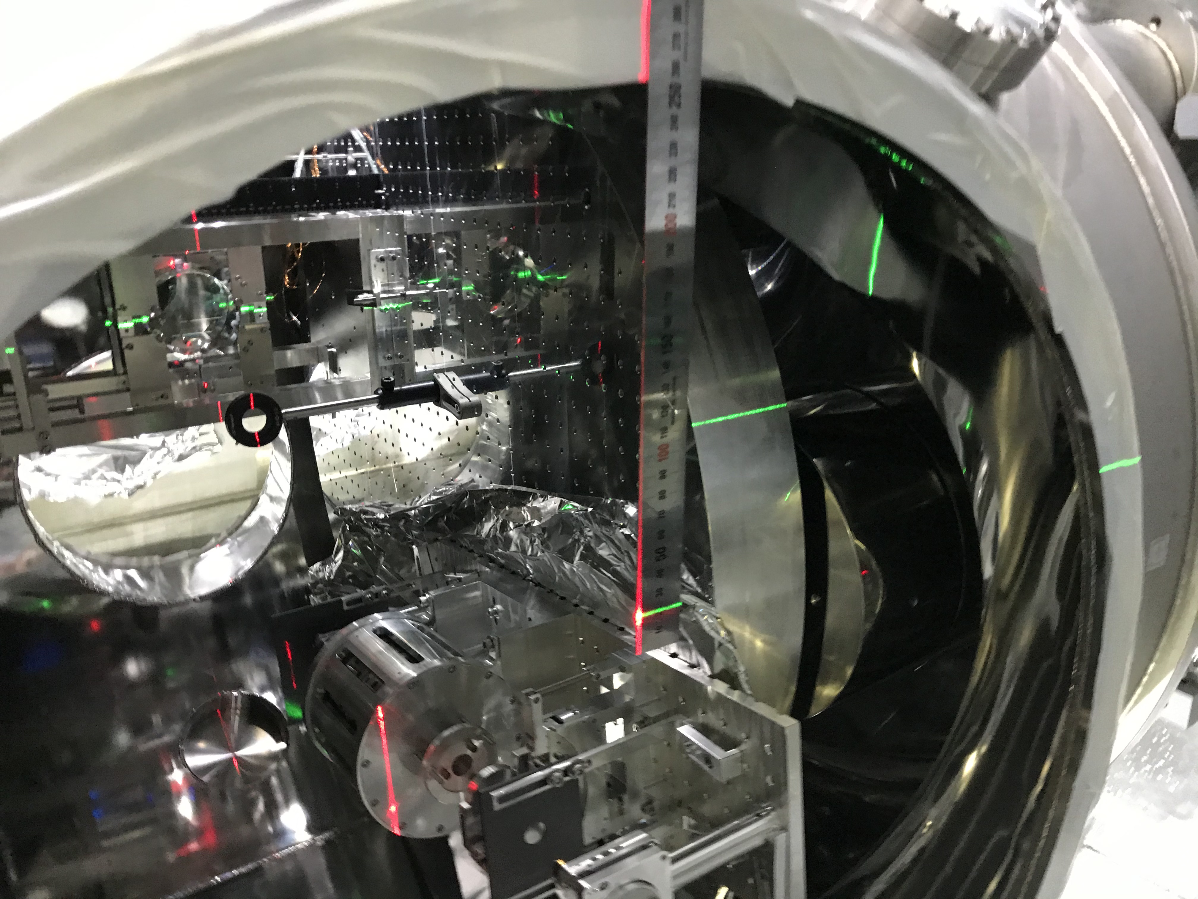
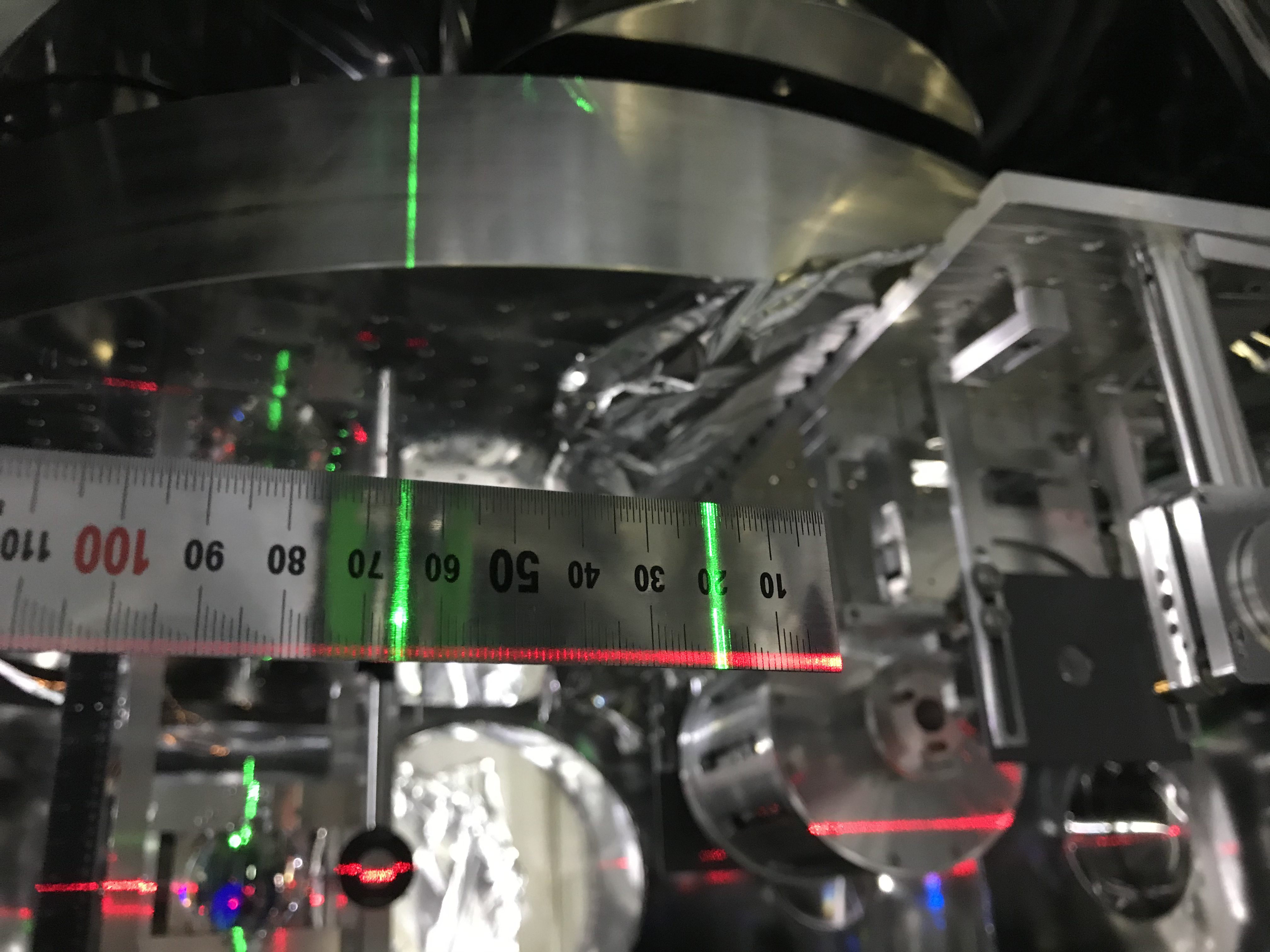
With the laser level horizontal mark (210 mm height on the IFI optical table and 207 mm for IMM optical table), we aligned STM2 so that the reflected beam from STM2 illuminated the pitch imaginary center of IMMT1 (the geometrical center was, as reported above, shifted 3 mm) by tweaking pitch adjuster of the STM2 holder. For yaw, we set another laser level (green light) to somehow make a vertical light line as an imaginary cross section in which the "designed" optical path would stay (including IFI... but as you know, IFI did not come back as of today in the real world), according to my rough cheat sheet. (Figs. 8 and 9) Fig. 10 shows a maker made for a reference point for the vertical laser level. To do this, we reset the red laser level to let it go along the diameter line of the -X flange of the IMM chamber (to measure the distance of the green laser level line from the flange edge), meaning have it illuminate 210 mm height on the IMM optical table --- as reported above, this corresponds to ~ 3 mm higher than the nominal height. This is just for a rough reference to know the yaw center of IMMT1. Anyway, by tweaking the yaw adjuster on the STM2 holder, we "centered" in yaw the beam on IMMT1 (Fig. 11; as the red laser level is 210mm on the IMM optical table in this photo, it is natural that the beam spot is slightly lower than this line).
By the way, when I checked the behind of IMMT1, the IMMT1 transmission beam seemed lay on the plane made of the IMMT1 oplev beams (input too and reflected by IMMT1). Here, the oplev setup was prepared by myself by referring several drawings around here and information, so the oplev setup and the input beam throuogh MCF (with IMC) - IFI - IMM chambers are independent. These independent things agrees with each other but exception is the IMM optical table height. So I suspect the wrong one is this IMM optical table or chamber... but I'm not sure. In the same reason, maybe the height of the mortar floor for the IMM chamber would be ok.
Beam alignment IMMT1 to IMMT2
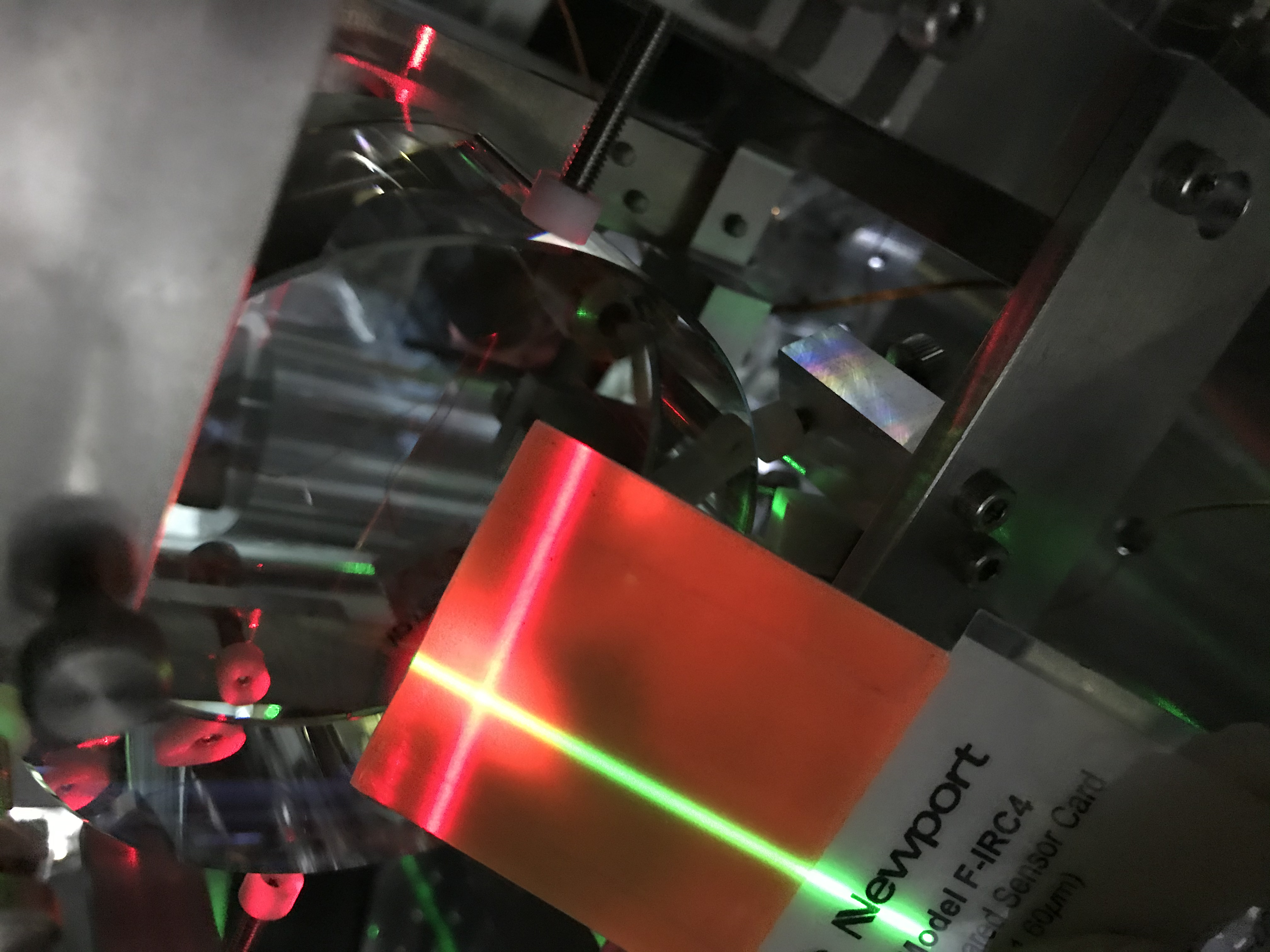
In the same method for IMMT2, the center markers was prepared (Figs. 12 and 13). First, Takahashi-san tweaked one of pitch picomotors on the IMMT1 cage to align the beam in pitch on IMMT2. Then, with positinors set around the base plate of the IMMT1 suspension structure cage, Takahashi-san and Tanaka-kun somehow slightly rotated the whole IMMT1 system so that the beam from IMMT1 illuinated the yaw center of IMMT2 (I checked with the sensor card; Fig. 14).
