(see also klogs 5134 and comments 5145 5146 and 5150)
We found the PMC PZT specifications (klog 5150) that was used in the PMC build: A modified PI P-025.xxH with ~3.7um displacement at 1000V, operating range of 0V to 1000V, and a nominal capacitance of ~45nF (+-20%).
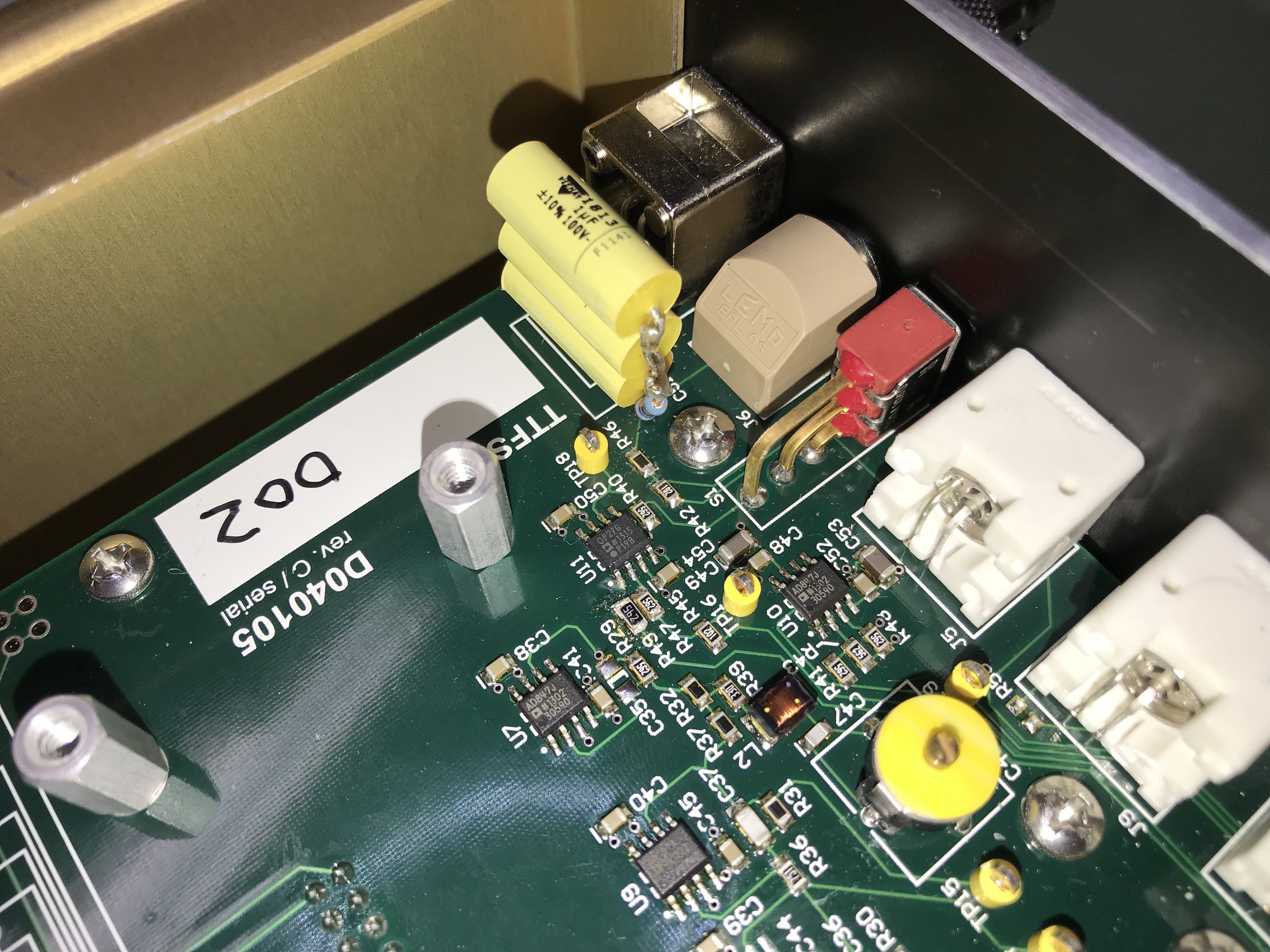
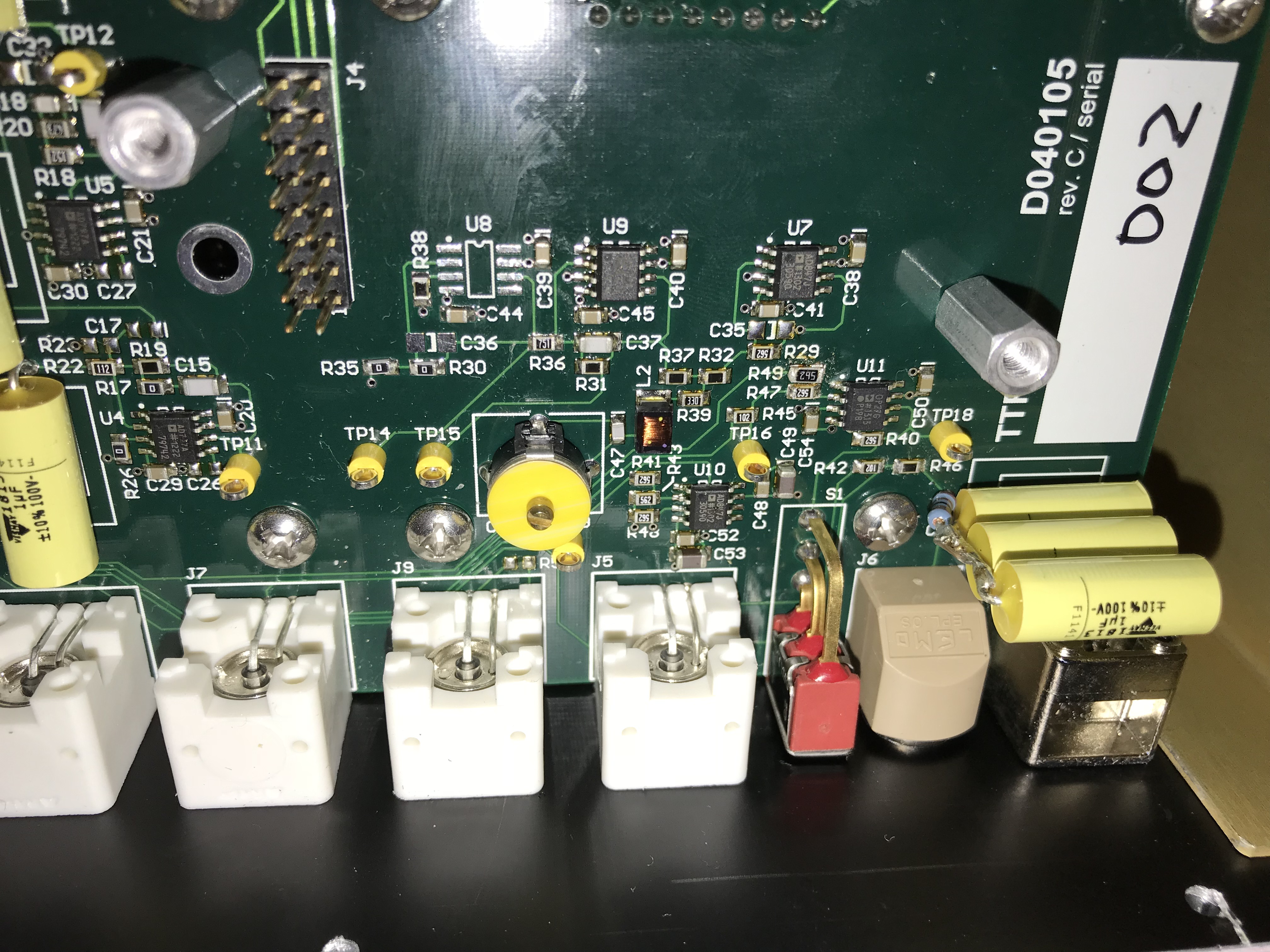
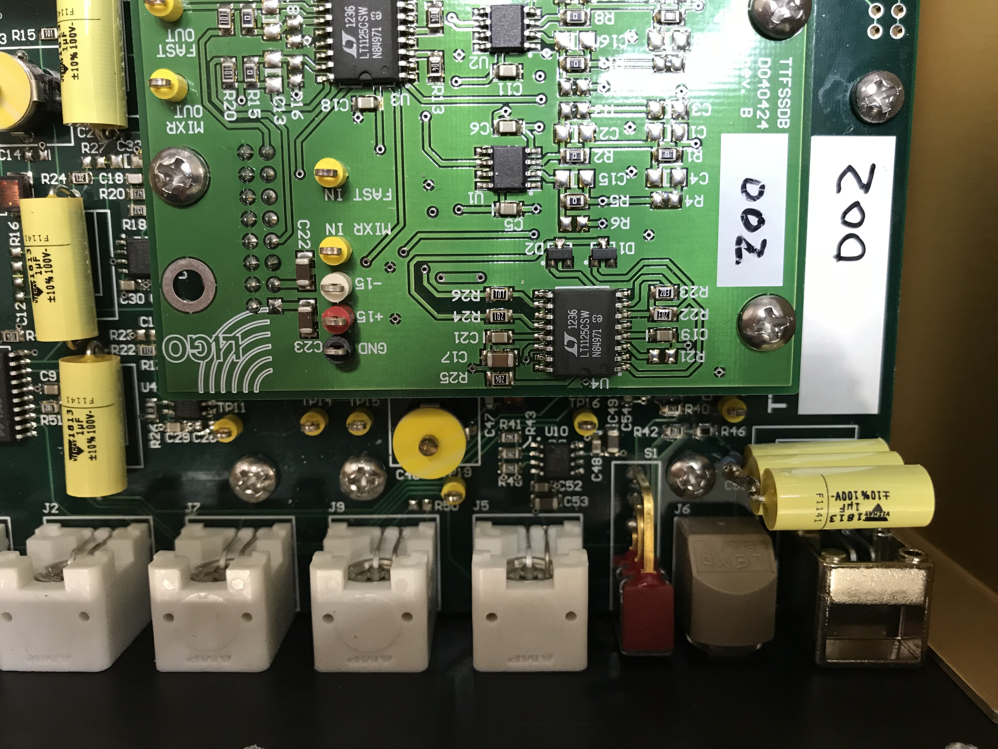
We went through the TTFSS schematics (see klog 5146) to figure out how we want to use the circuit to control the PMC.
*The PMC PZT will be driven by a Matsusada PZDE-0.3B high voltage driver. It has a range of -300V to 300V, but we will only use 0 to 300V. Also, it has a manual bias, which we will set to 150V.
*The main integrator will be formed by a passive pole network at the output of the PZDE-0.3B. For noise reasons the passive pole frequency fpp should be chosen as low as feasible given physical component constraints.
*We plan to use the TTFSS FAST path to drive the PZDE-0.3B, We can either use OUT2 (J5) or modify the passive pole in the FAST path output and use the FAST OUT (J8, TNC). If fpp from the previous bullet is too high, we can use R46 and C51 to form an even lower pole frequency, and a zero at fpp (or higher is we want extra low frequency boosting).
*For locking we will need an output offset adjust. This required changing R49 from 56K to 5.6K (to get full 10V range), and hooking an additional DAC output up to EXC J9. (We couldn't figure out from schematics where to take that from.)
*If we want extra low frequency boosting, we can add that at U8 and U9. Something like a 1Hz to 100Hz pole zero. The 34kHz pole is fine for signal roll-off.
*The board still drives the high voltage EOM output, which is not used. That is fine, but we should verify that it does not saturate in lock. If it does, we can cut that trace at the cable between LIGO-D040105 and LIGO-D0901893, and ground the input to LIGO-D0901893.
*Finally, estimating the PMC thermal drift, we will likely need a thermal actuation as well. We can drive it directly from the TTFSS SLOW output, but we have not checked the driver requirements of the PMC thermal drive input.
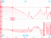
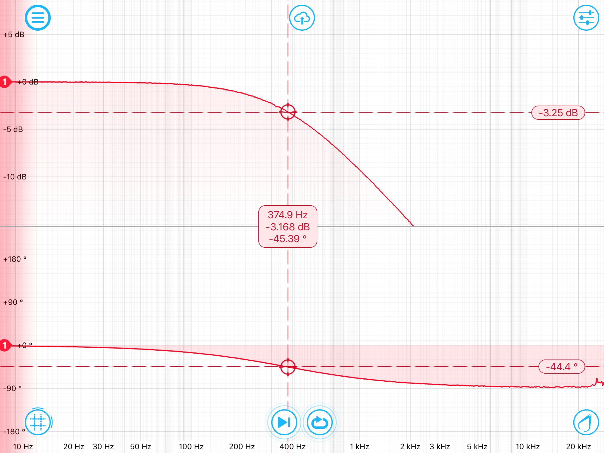
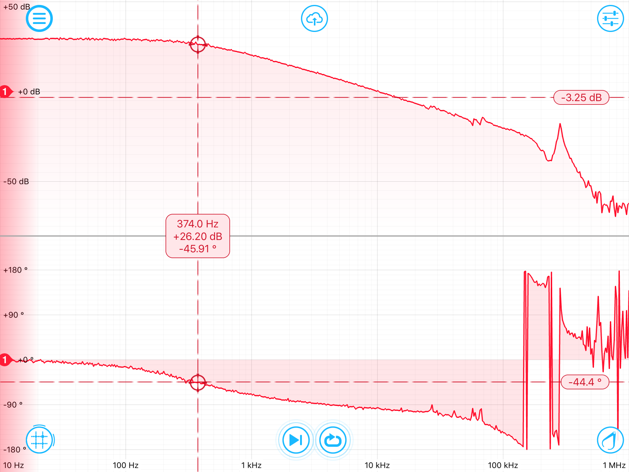
Plot 1 shows the Mokulab transfer function of the 10KOhm plus PZT.
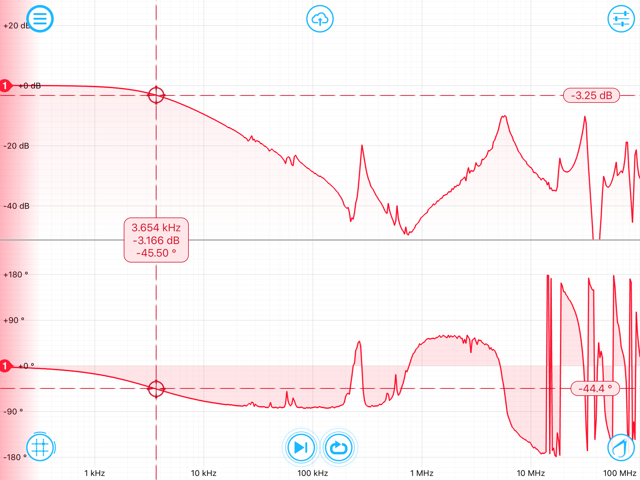
Plot 2 shows the same same transfer function of this passive drive, but with a 1kOhm resistor and up to 100MHz.
Plot 3 again uses the 10kOhm resister, but includes the HV amplifier in the transfer function. It has a factor of 30 gain at DC.
For operations I suggest:
- Using a 100kOhm resistor, which makes a 37.5kHz pole.
- In addition, on D040105 (modified TTFSS for PMC), changing C51 to 3uF in series with a 1.3kOhm resistor will add a 3.4Hz:40.8Hz pole zero, moving the integration pole to 3.4Hz.

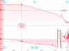
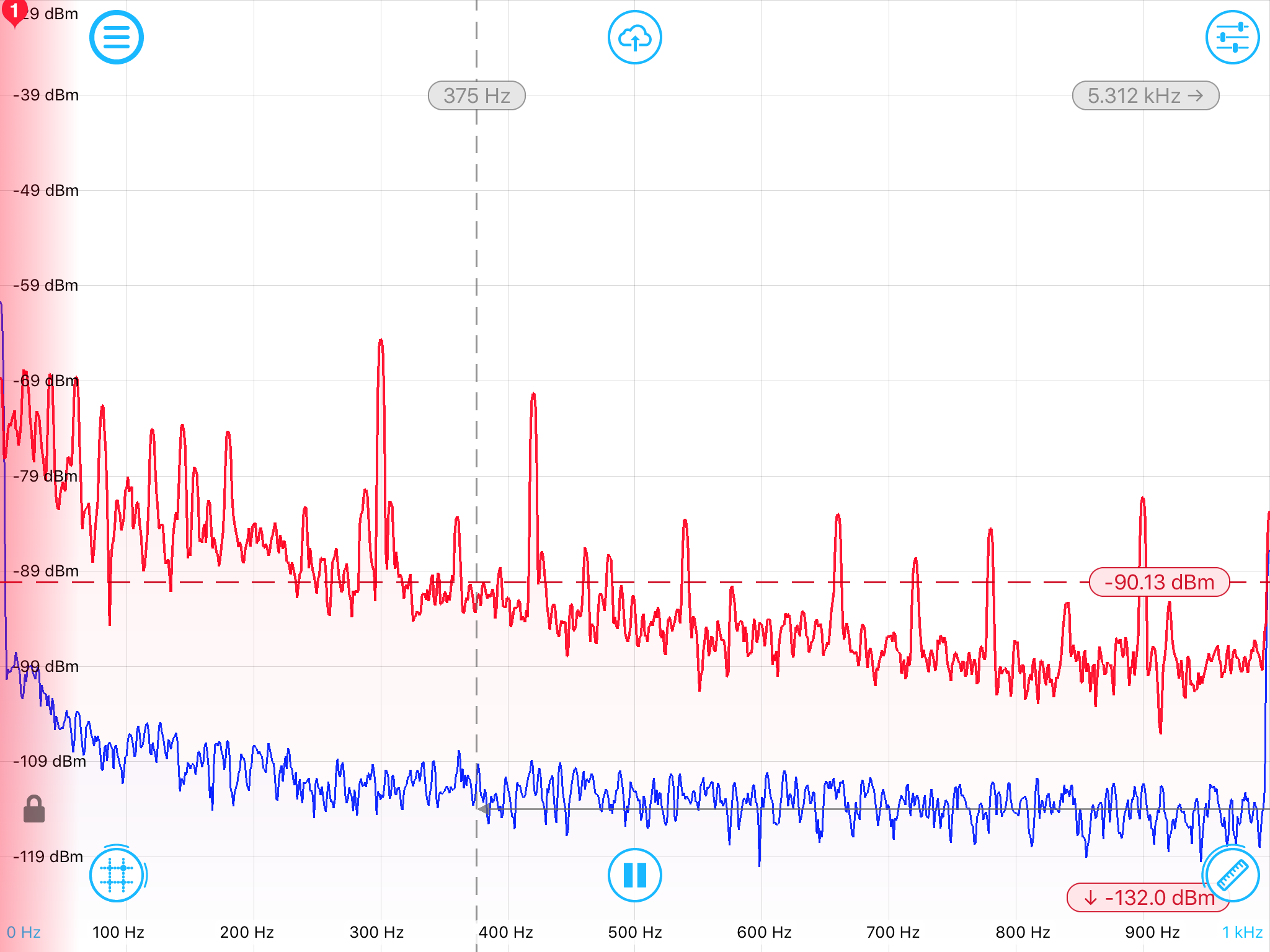
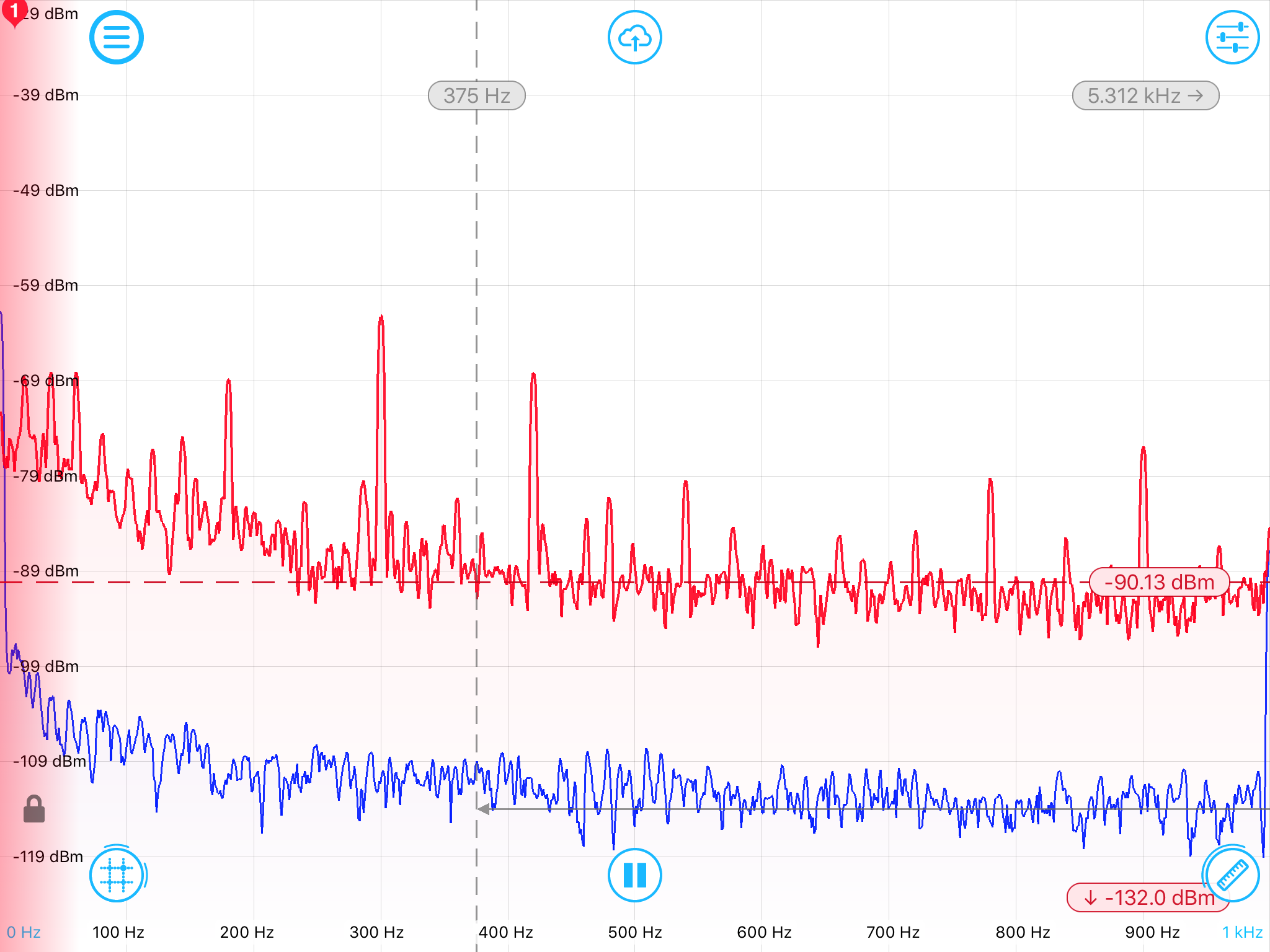
Attached are two raw noise measurements Matsusada PZDE-0.3B High Voltage driver.
- Plot 1 with the PZT attached after a 10kOhm resister, producing a 375Hz pole.
- Plot 2 without the PZT attached.
Note that MokuLab reports dBm, even though the input is on 1MOhm (and I could not find out how to change it). While this makes no sense to me, I assume Mokulab assumes 50Ohm...
With that, the typical noise level around 100Hz is -80 to -90 dBm (lots of lines).
That would correspond to
- -80dB --> 10^(-80/20)*sqrt(50*0.001) Vrms = 22uVrms
- -90dB --> 10^(-90/20)*sqrt(50*0.001) Vrms = 7uVrms
If I use the nominal 2*3.7um/1000V PZT actuation coefficient (2* since the optical path length is twice the mirror displacement), I get
- -80dB --> 1.7e-13 meter rms
- -90dB --> 5.2e-14 meter rms
for the induced PMC length noise


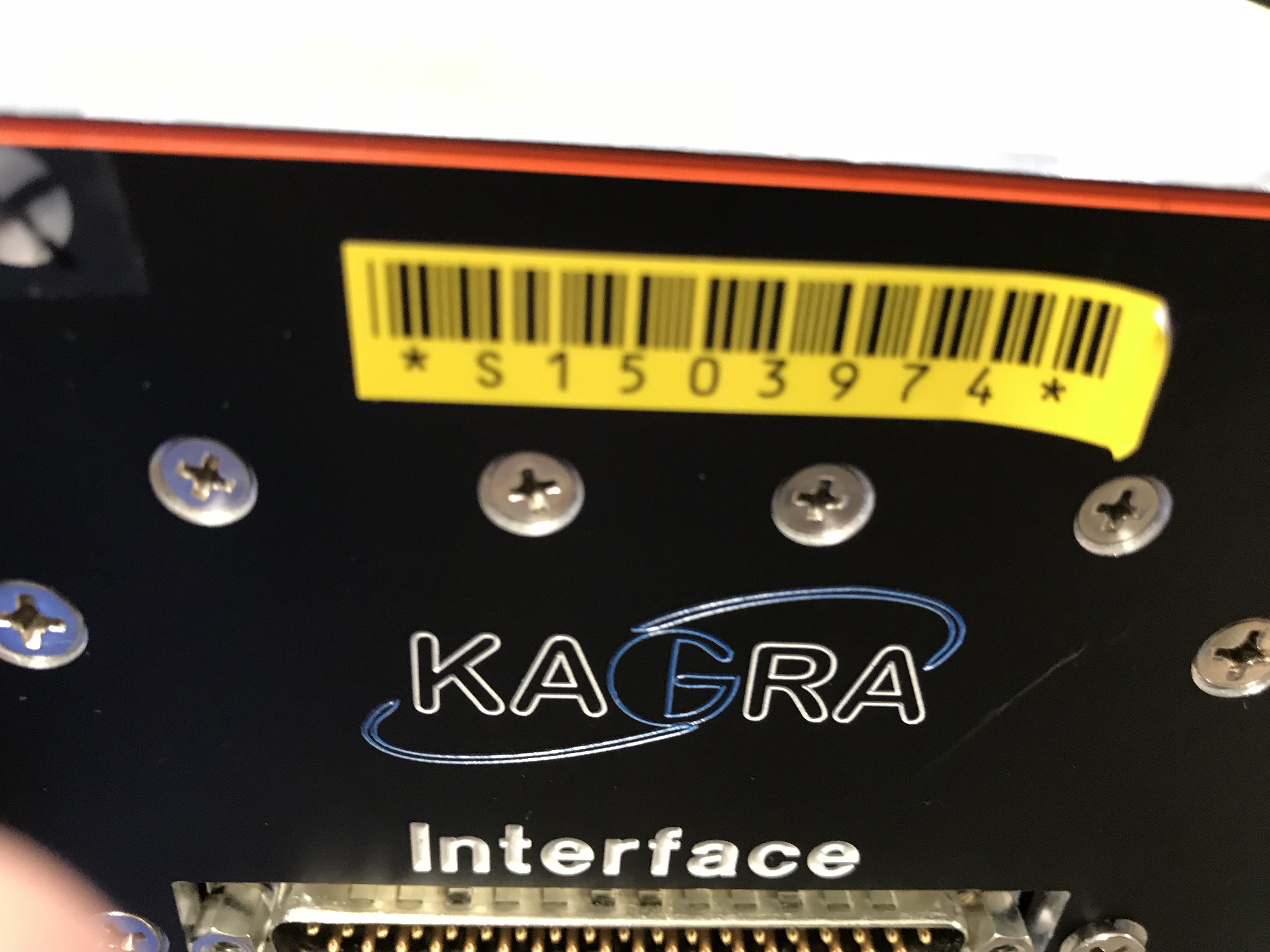
This is Serial No S1503974.
PDF1: Schematic
PDF2: Front Panel
PDF3: Rear Panel
PDF4: Chassis
PDF5: Parts list
PDF6: Drawing
See also klog 5166 for pictures of the PMC heater wiring and heater plates.
Link to klog 5170.
Link to klog 5174.
klog 5146: TTFSS board schematics
klog 5150: PZT spec and purchase order, Rick's PMC presentation and TTFSS Interface board schematic.
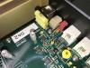
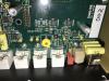
- Removed R4 on the TTFSS Slow board (D0901895) to gain the full +-10V range for the SLOW output, which will be used as an output offset (connecting it to the FAST EXC point).
- Disconnected the High Voltage Opamp PA98A (U6 on the TTFSS:HV/Inteface board D0901893). The opamp is socketed, so I just pulled it out of its socket and mounted it to the back panel for possible future use. This takes the HV path out of action, an we don:t have to worry about saturations in that path.
This is in response to klog 5331 and should get us more DC range on the PMC PZT.
It should also get us a factor of 15 or so more actuation authority on the slow loop.
The UGF at the nominal gain setting of +10dB common gain and +10dB fast gain is 7kHz. Please ignore the open loop transfer function given in klog 5372.