1) We switched back to the 100kOhm series resistor at the output of the HV driver. This forms a 37Hz passive pole.
2) 37Hz turns out to be too high for reliable locking. So we needed a pole-zero pair at about 8.2Hz and 41Hz, which was realized with a passive network in a pomona box at the input of the HV driver.
3) Finally, we needed to roll off the signal above about 7kHz to avoid ringing up PZT resonances. This is also done in the pomona box at the input of the HV driver.
In summary, the pomona box at the input of the HV driver includes:
- A 10kOhm series resistor for driver range matching
- A 1.3 kOhm resistor and a 3uF capacitor to ground (actually 3 1uF caps in parallel), forming a 8.2Hz:41Hz pole zero pair.
- A 22nF capacitor to ground in parallel to the 10kOhm load, forming a ~7kHz pole.
WIth those two pomona boxes, the servo runs reliably at ~3kHz Unity Gain Frequency.
Attached are:
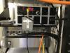
Picture 1: The Pomona box with the passive network. The label is the schematic.
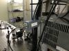
Picture 2: The 100kOhm series resistor pomona box.
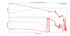
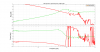
Plot 3: Open loop gain and closed loop gain measurement of the PMC at the nominal gain setting of +10dB common gain and +10dB fast gain.
File 4: Text data for the open loop gain measurement; frequency, real(OLG), imag(OLG). The file contains high resolution around the PZT resonances.
Also see klog 5155 for a history of all modifications.
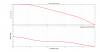
1) The Pomona box at the input of the HV amplifier (i.e. between PMC-TTFSS and HV amplifier).
2) The Pomona box series resistor at the output of the HV amplifier.
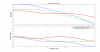
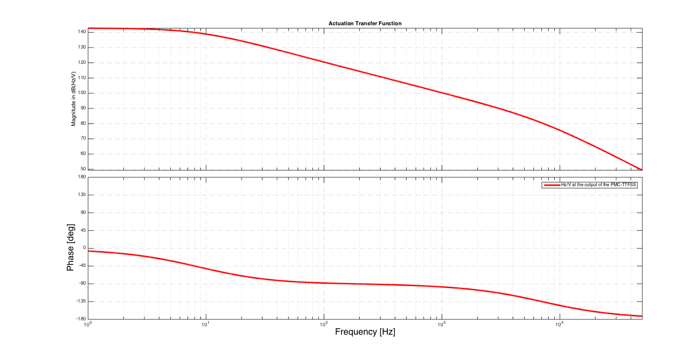
3) The total actuation transfer function after the HV amplifier.
Also, the measured PZT gain is 167V/FSR, with a 154MHz FSR, giving a PZT gain of 922kHz/V on the PZT.
Plot 2 shows the total actuation transfer function out of the PMC TTFS servo box in dB(Hz/V).
See also klog 5155, 5372 and 5373.
At the nominal gain setting of +10dB common gain and +10dB of fast gain we have a UGF of 7kHz.
Attached are the correct open loop gain and closed loop gain transfer functions plots, as well as the raw data (frequency, real(OLG), imag (OLG).
Also see klog 5155 for a history of all modifications.