I added the result for Prometheus 2143 A to the plot of the absolute frequency measurement (klog7375).
The raw data for each laser is attached as well.
I added the result for Prometheus 2143 A to the plot of the absolute frequency measurement (klog7375).
The raw data for each laser is attached as well.
Today, I tried to get the beat-note signal between the PSL and the Prometheus laser for Y arm.
Firstly, I aligned the beam path using steering mirror so that the two beams interfere. Then I sweep the crystal temperature of the Prometheus with my hand and the beat-note signal was detected around 40 MHz when the crystal temperature was 25.22 deg.
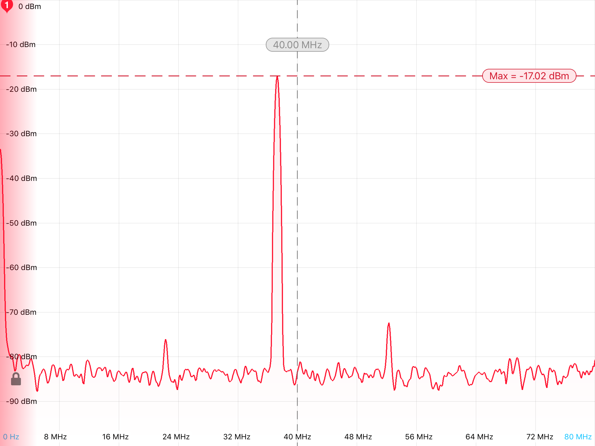
When the above beat-note signal was detected, the lasers power in front of the PD are following.
Since the main laser power is lower than assumed, the amplitude of the beat-note was -17 dBm. (We require the beat-note with amplitude of -11 dBm.)
[Sugimoto, Yokogawa]
We brought dichroic mirrors(*2) and harmonic splitter(*1) from the PSL room to the POS table.
Dichroic mirrors are used for the periscope on the POS table. Harmonic splitter is used to separate IR and green on the POS table.
[Yokozawa, Enomoto, Sugimoto, Yokogawa]
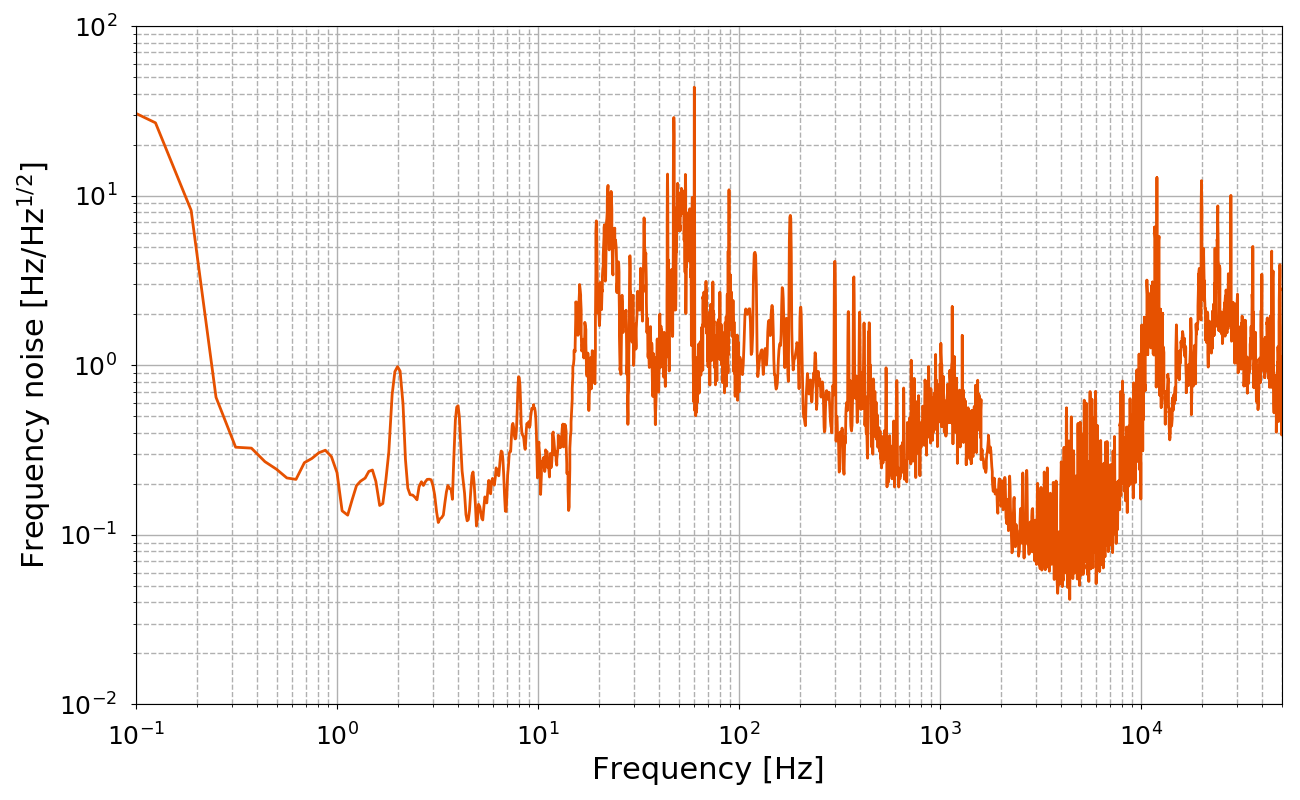
We measured the fiber noise today.
Related log:
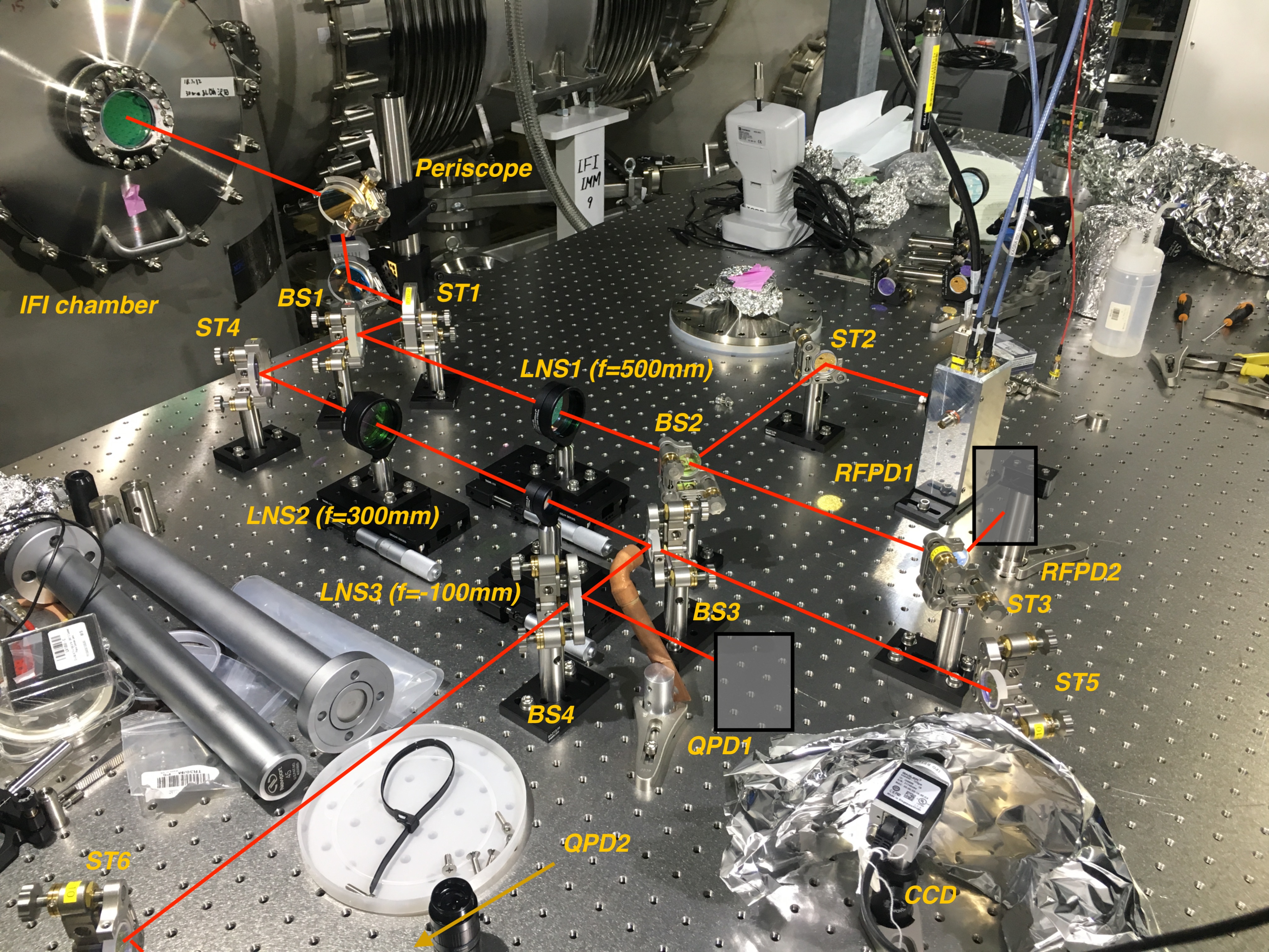
The fist attachment is the layout of this measurement.
1. The green laser beam on the POP table is sent back to the PSL table using a spare fiber.
2. We detect the beat-note signal between two beams. One is through two fibers and the other is not through the fiber. There is a frequency difference of about 160 MHz for two beams since the beam passing through the fibers also passes through the AOM for shifting frequency. Therefore, the beat-note signal is obtained in 160 MHz.
3. The frequency difference is controled by PLL. The beat-note signal is locked in 160 MHz by PLL using PFD, MC servo (for CARM loop) and AOM VCO.
4. The noise of the control signal is measured and calibrated to the fiber noise. The fiber frequency noise is obtained by multiplying the control signal by the actuator factor of AOM VCO (0.42 MHz/V).
During this measurement, we swiched off all FFUs around MC, PR, BS areas, KOACH filters for PSL room and one precise air conditioner for PSL room.
This is the measured fiber noise. This is calibrated by multiplying the measured control signal by 0.42 MHz/V and dividing by 2 since the measured noise has the noise for two fibers.
There is the large structure at 10-100 Hz. We will incorporate this noise into the noise budget and compare to the measured ALS noise.
[Enomoto, Sugimoto, Yokogawa]
We tried to couple the green beam for Y arm to the optical fiber last week and this week.
What we did:
(on Dec. 21st)
(on Dec. 26th)
(on Dec. 27th)
(on Dec. 28th)
[Sugimoto, Yokogawa]
Related log:
Today, the main laser temperature was changed from 46.5 deg to 49.13 in order to get the beat-note signal between the main laser and the new PROMETHEUS laser for Y arm. Along with this, we changed the tamperature of the PROMETHEUS laser for X arm from 25.5 deg to 26.8 deg referencing this plot so that the frequency of the beat-note signal is 40 MHz.
Finaly, we got the beat-note signal and the PROMETHEUS X laser was phase-locked to the main laser by PLL without problems.
[Izumi, Sugimoto, Yokogawa]
We proceeded with the preparation for the ALS Y arm system.
Related log about fiber installation:
The optical fiber which transmit green beam for ALSY system from the PSL table to the POS table was laid to aroud the POP table and the rest of the fiber was rolled and placed on the LSC rack beacause the POS table had not been installed when the optical fiber was laid by Fujitsu Fsas. Since the POS table was installed on Nov. 9th (log6930), we laid the rest of the fiber to the POS table today.
What we did:
(I forgot to take pictures after the work of numbers 4 and 5.)
Yesterday, the new PROMETHEUS laser was installed (log7384), so we aligned optics for ALSY system on the PSL table. Current status is following.
Green path: All the optics except the fiber coupler was aligned. It is necessary to bring the fiber coupler stored at Univ. of Toyama.
IR path: All the optics have not been aligned yet.
Kazuya, Ryousuke, Kiwamu,
--- An addendum.
We learned that there was a portion where the fibers were not covered by the yellow jacket under the black tubing presumably at each end of the duplex fiber.
The message here is that one can easily put himself or herself into a sad situation where the fiber is unintentionally damaged when he or she tries to remove a black tubing because of the facts that the black tubings are not easy to remove and the fibers are exposed under the tubings. So don't remove them unless you have a good reason to do it.
Since we didn't know this fact, we actually almost removed the black tubing at the end of the duplex green fiber on the POS table. We originally thought that removing the black tubing would enable us to further split the two fibers so that one can separately isolate them from some vibration in easier fashion. The black tubing seemed to have been glued on to the yellow jacket. So we used a wire cutter to carefully take the tubing off without damaging the fibers. Then realizing that a few mm long portion of the fibers were exposed out of the yellow jacket, we stopped removing it and subsequently re-wrapped the black tubings with the aid of Kapton tapes around it. See the first attachment for a picture of the fiber end that is now taped by Kapton. As seen in the picture, we also put a small caution label so that no one will remove the tubings in future.
After this, we additionally made sure that both A and B fibers can still transmit some light using a fiber checker which emits red-ish visible light.
For some reason, the picture that I attached disappeared. Hence this log with the same attachment.
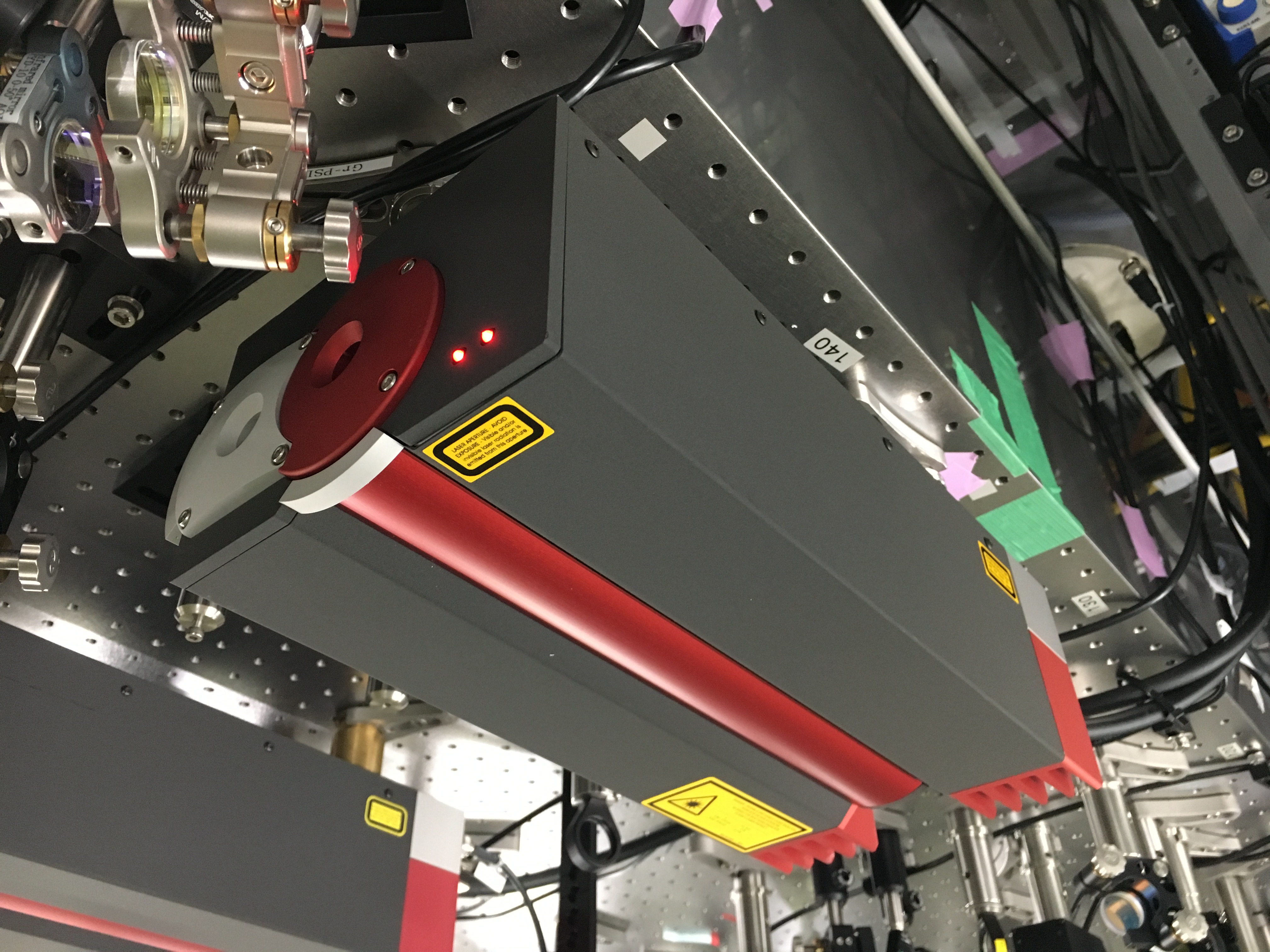
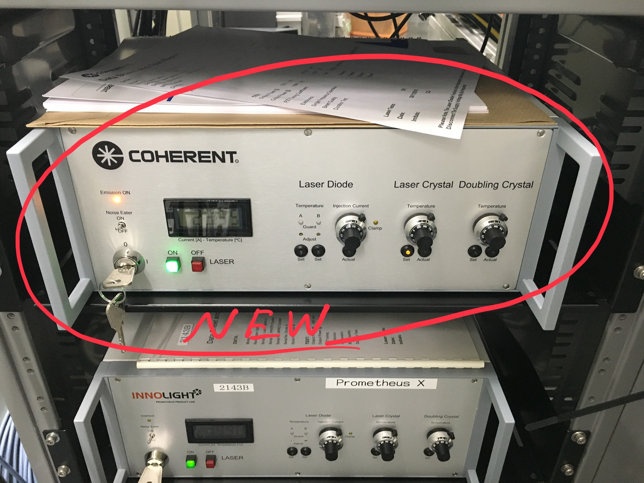
Before saying about the frequency measurement, I should have mentioned about a important thing. The new PROMETHEUS laser was delivered to Mozumi in this morning, so we took it to the PSL room and swapped the problematic PROMETHEUS laser for the new one. The problematic one will be sent for repair to the manufacturer.
NOTE
Since we put the new laser loughly, we have to start the alignment from scratch.
[Izumi, Eleonora, Yokogawa]
Related klog: #6239
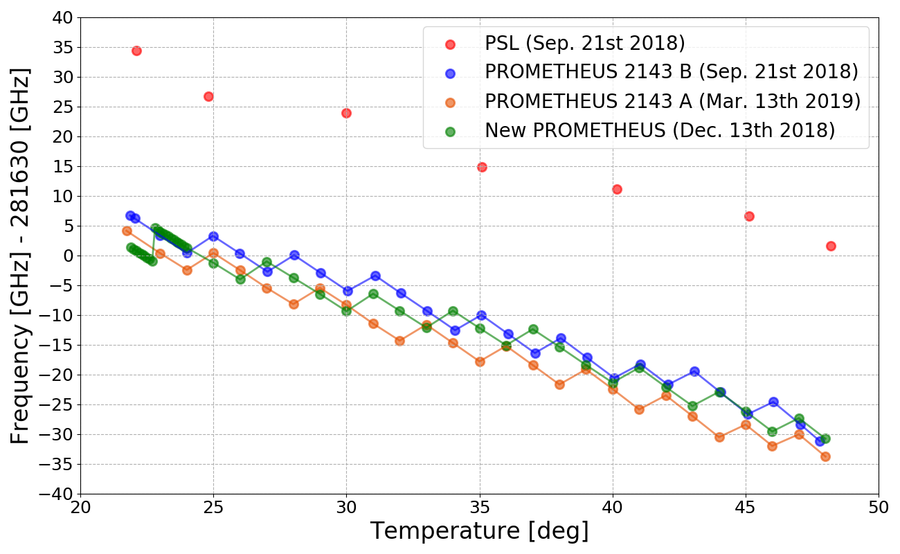
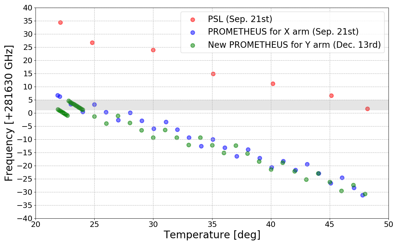
Today, the new PROMETHEUS laser for ALS (Y arm) system was delivered, so we measured frequency of this laser by tuning the crystal temperature.
The attached figure shows the result. Green dots show the measurement result of the new PROMETHEUS laser. Also, the measurement result of the main laser and the PROMETHEUS laser for X arm measured on Sep. 21st are shown in red and blue dots respectively. The frequency differences between the main laser and two PROMETHEUS lasers need to be around 40 MHz since the beat-note signal is locked to 40 MHz by PLL. However, the overlap range (gray region) is very narrow and the frequency of the main laser can be set only every 1.5 GHz in order to lock the main laser to the reference cavity. (FSR of the reference cavity is 1.5 GHz.)
I believe that the beat-note signal for ALS Y arm system can be seen...
Before saying about the frequency measurement, I should have mentioned about a important thing. The new PROMETHEUS laser was delivered to Mozumi in this morning, so we took it to the PSL room and swapped the problematic PROMETHEUS laser for the new one. The problematic one will be sent for repair to the manufacturer.
NOTE
Since we put the new laser loughly, we have to start the alignment from scratch.
For the book keeping purpose, here is a list of the log entries that describe the history the old Prometheus (2143A).
[Enomoto, Yokogawa]
What we did:
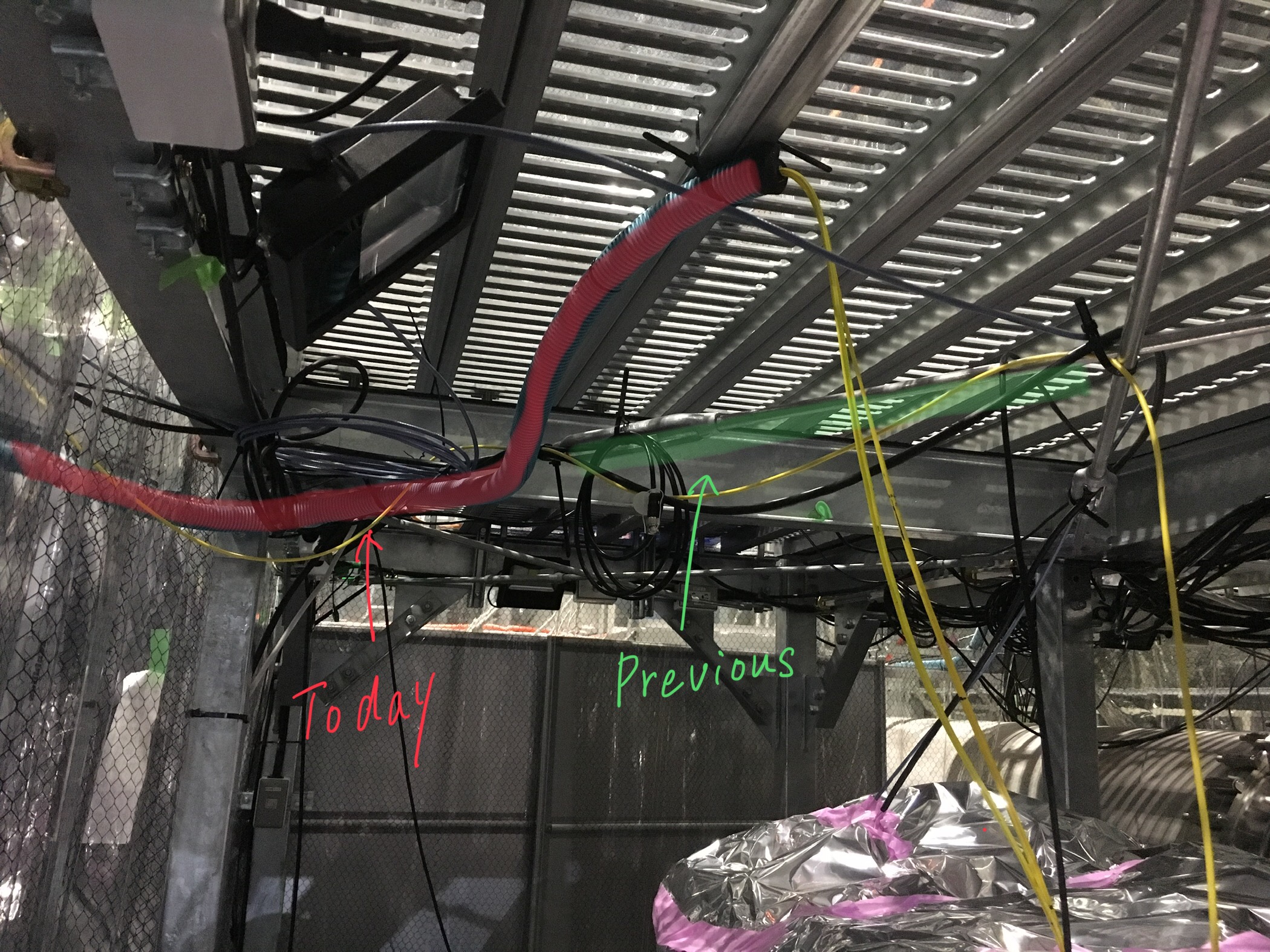
1. re-fixed the optical fiber over the POP table. (Fig.1)
The optical fiber was re-fixed using the floor of BS booth 2nd floor, since the bar holding the fiber was flexible.
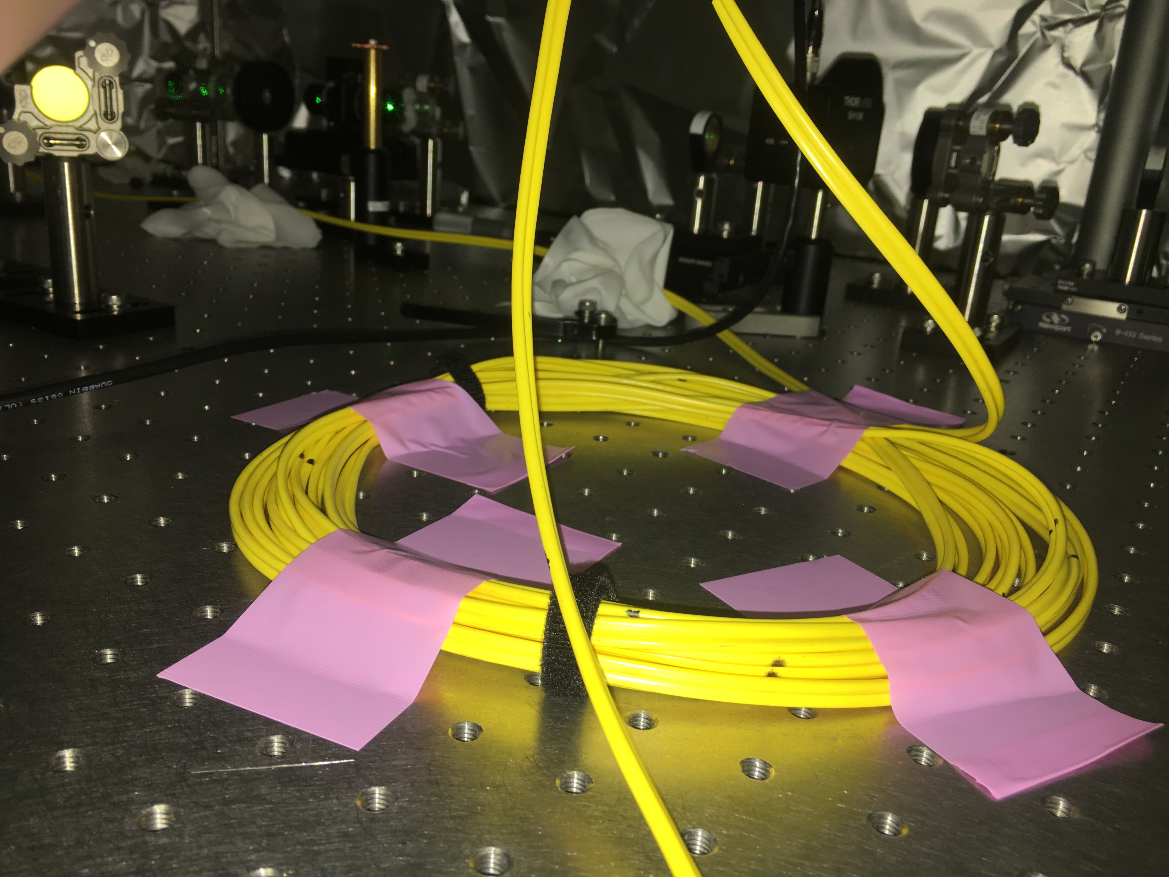
2. fixed the fiber to the POP table with masking tape. (Fig.2)
[Nakano, Enomoto, Sugimoto, Yokogawa]
(Yesterday work)
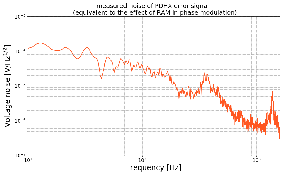
We suspected that the effect of RAM in phase modulation by Gr EOM is limiting the frequency stability (the above plot) and investigated the effect of RAM.
The attached figure is measured noise of the PDH error signal which taken at the I-phase output of I&Q demodulator for Gr PDHX. This is equivalent to the effect of RAM(Residual Amplitude Modulation) in phase modulation by Gr EOM. This noise seems to have the same shape as the noise of the PDH control signal (black line in above plot) especially at around 350 Hz and 1.x kHz. However, it was concluded that the factor of limiting the frequency stability is not the effect of RAM, since the effect of RAM should be a lower noise level in the frequency noise from simple calculations.
The data is stored at:
KAGRA Dropbox/Personal/Yokogawa/PDH/20181121
[Miyoki, Enomoto, Sugimoto, yokogawa]
(Yesterday work)
We installed the optics on the REFL table and aligned those optics using the reflected beam from ITMX.
what we did:
NOTE:
Since we did not have one RFPD and two QPDs, they have not installed yet.
Hi Enomoto-san,
I ploted the free-run frequency noise of the PROMETHEUS laser considering the effect of the anti-whitening.
The blue line is the frequency noise measured last Thuersday and the orange line is the frequency noise considering the anti-whetening. This plot looks like 1/f shape. Also, the green line is the free-run frequency noise of the PROMETHEUS laser measured on Oct. 11th with Enomoto-san.
[Izumi, Yokogawa]
Yesterday, it was confirmed that the broadband structure from 1 Hz to 100 Hz on the PLL feedback spectrum disappeared as we swiched off the KOACH air system (log6796), but there was flat noise after around 10 Hz.
We concluded that these noise is freerun frequency noise of the PROMETHEUS laser.
what we did:


Hi Yokogawa-kun,
Which channel did you use as a monitor of the feedback signal of PLLX? K1:ALS-PLLX_SLOW_DAQ_OUT(_DQ)?
If so, we haven't implemented an anti-whitening filter for this channel, which means that value of this channel is different from the voltage of the feedback signal in the real world, by a 2nd order whitening filter (two zeros at 10Hz and two poles at 100Hz, DC gain of 2).
We need an anti-whitening filter same as the one implemented in the filter module K1:ALSPDH_PDHX_SLOW_DAQ.
(I implemented such filters only for K1:ALS-PDH{X|Y}_SLOW_DAQ_OUT. Sorry for this confusion.)

And my implementation of the anti-whitening filter by eyes to the spectrum gives me less-structured 1/f shape. This must be free-run noise!
Hi Enomoto-san,
I ploted the free-run frequency noise of the PROMETHEUS laser considering the effect of the anti-whitening.
The blue line is the frequency noise measured last Thuersday and the orange line is the frequency noise considering the anti-whetening. This plot looks like 1/f shape. Also, the green line is the free-run frequency noise of the PROMETHEUS laser measured on Oct. 11th with Enomoto-san.
Great!
(By the way, the plot has disappeared at some point.)
To avoid further confusion, I implemented anti-whitening filters for CMSBs named as PLLX, PLLY, Summing node, and CARM servo.
Then updated the safe.snap of k1alspll
[Izumi, Sugimoto, Yokogawa]
Yesterday, Izumi-san found that the noise of the PLLX control signal are higher than before. Since, these noise had coherence with the microphone in the PSL room, we assumed that the couse of noise increse was acoustic noise. We confirmed the folloing two points.
Since it was found that the noise increased due to the wind from the KOACH, we confirmed the noise when we knocked the optics for IR beam path in order to see if the wind was shaking the optics. However, even if we knocked the optics, there was no change in the noise. Also, even when the KOACH is on, the noise sometimes became peliodically smaller. That was strange.
Since the power of the main IR beam was raised about 3 times by Nakano-san, we adjusted the beam power before the RFPD for detecting the beatnote. The folloing table shows the beam power of the main laser (MEPHISTO) side and the AUX laser (PROMETHEUS) side before the RFPD and the amplitude of the beatnote before and after adjusting the power.
| Before | After | |
| MEPHISTO side IR beam power | 2.5 mW | 7 mW |
| PROMETHEUS side IR beam power | 8.5 mW | 8 mW |
| Beatnote amplitude | -17 dBm | -11 dBm |
Some additional data:
Here is a screenshot of the PLL feedback spectrum with and without KOACH on, taken in this after noon. The broadband structure from 1-100 Hz and a peak at around 200 Hz disappeared as we switched off the KOACH air system. Also, when the KOACH is on, we see high coherence in the same frequency band, indicating somehow the wind couples to the PLL.
By the way, we believe that noise 1 Hz is free-run frequency noise of the Prometheus laser.
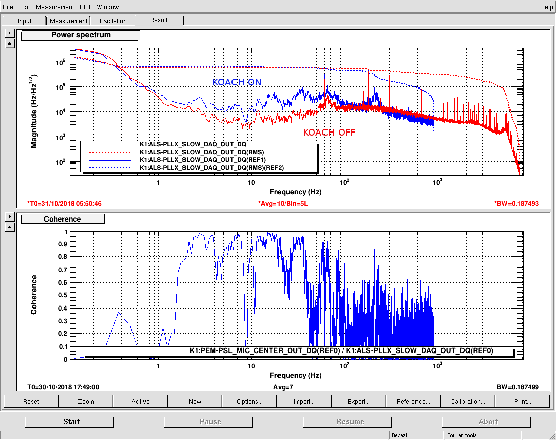
The data is stored in the xml format at:
/users/Commissioning/ALS/PLL/ALS_PLLX_with_without_KOACH_20181031.xml
Erratum:
The diaggul xml file was stored in the following page. Sorry for any confusion.
/users/Commissioning/data/ALS/PLL/ALS_PLLX_with_without_KOACH_20181031.xml
[Izumi, Sugimoto, Yokogawa]
In preparation for the characterization of PLL, we measured noise of Common Mode Servo Board (CMB) for PLLX. The condition of CMB in our measurement are following.
We could not turn on the common boost (1, 2 and 3) because the slow output of CMB saturated. The other settings are the same as when PLL is locked.
The attached is the noise of CMB for PLLX measured by Agilent 35670A. The graph is plotted by connecting the data measured three times while varying the stop frequency of the measuring instrument at 100Hz, 1.6kHz and 51.2kHz.
The data are uploaded in /KAGRA/Dropbox/Personal/Yokogawa/PLL/noise/20181024.

[Enomoto, Sugimoto, Yokogawa]
(Yesterday work)
We tried automating the PLL and succeeded!
The procedure of PLL;
It is difficult to judge the lock because the Phase Frequency Discriminator (PFD) outputs a sawtooth wave. (The output signal of the PFD is an error signal for PLL.) PFD outputs -4 V when the beatnote frequency is higher than the local frequency and outputs +4 V when the beatnote frequency is lower than the local frequency. If the beatnote frequency is close to the local frequency, the PFD outputs a sawtooth wave.
So, we decided that PLL is locked when the PROMETHEUS frequency is 40MHz lower than the main laser frequency and the beatnote frequency approaches the local frequency from the lower ferequency side by sweeping the PROMETHEUS temperature. Specifically, when the current and the previous value of the error signal and the direction of sweeping temperature satisfy the following expression, PLL is locked.
( (Error signal CURRENT value) - (Error signal PREVIOUS value) ) * (Temperature sweep direction) < 0
[Enomoto, Yokogawa]
We measured OLTF and noise spectrum of PLL.
This is the measured OLTF of PLL. UGF was 35.6 kHz.

We measured noise spectrum of the control signal and error signal by 35670A (Agilent). I will post the details such as caliblation tomorrow, but I post frequency fluctuation of a Prometheus laser estimated by measured noise spectrum. The frequency fluctuation of a Prometheus laser is obtained by multiplying the noise spectrum of the control signal and the actuator efficiency of laser PZT (1.4 MHz/V) if we assume that the open loop gain is much larger than 1. Below is an estimated Prometheus laser frequency fluctuation.

[Enomoto, Midooka, Yokogawa]
We did phase lock a Prometheus to the main laser!! The attached figure is the beatnote signal during control.

What we did;
Next;
[Izumi, Enomoto, Midooka, Yokogawa]
log on 26th.
We set up the Common Mode Servo Board for ALS PDH to run with realtime model.
It seems that the signal is correctly output!
[Midooka, Yokogawa]
We installed shelves for ALS signal generator. (See the attached picture1.)
.
We installed the a DCPD on the POP table in order to monitor the power of fiber transmitted beam. But the cable has not been connect yet.
[Midooka, Yokogawa]
The crystal temperature of the main laser (Mephisto) was changed from 27 degree to 46.4 degree by Nakano-san. Then we found the beatnote between the main laser and a Prometheus by sweeping the Prometheus temperature.

[Michimura, Enomoto, Sugimoto, Yokogawa]
Yesterday, Michimura-san and Enomoto-san found that the DAC chassis (Ser. Num JGW-S1605872 ) gives an oscillated signal at ~1MHz. So, we changed to the new DAC chassis (Ser. Num JGW-S1605870) and used Low Path Filter in order to avoid the oscillation at 1MHz.
However, it was not the real reason why the beam shutter does not work in trigger mode. The point of the real reason was at ground. We found that outside the BNCs of the DAC chassis are not grouded in default. So, we connected the outside of BNC to the ground of DC power supply. (See the attached picture.) By doing so, the beam shutter worked with trigger mode!!
But this is not cool. We will drop the outside of BNC to ground using jumper pin.
Summary
[Izumi, Sugimoto, Yokogawa]
We measured the frequency of the KAGRA main laser and the Prometheus(Xarm) with respect to the laser crystal temperature. We used wavelength meter(Highfinesse WS Ultimate 30) for this measurement. Blue marker is the KAGRA main laser and green marker is the Prometheus for Xarm. For reference, I plotted the data of Mephisto in U. Toyama which was measured last year as red marker.
In order to take beatnote between the main laser and the Prometheus, it is nessesary to bring frequencies of two laser closer. However it seems that the frequencies approach only when the main laser temperature is very high and the Prometheus temperature is very low. Furthermore, the overlap range is narrow.

[Michimura, Enomoto, Takeda, Sugimoto, Yokogawa]
What we did:


The oplev values of PR3 when the beams hit the PD are folloing.
| Green | IR | |
| PIT | -83 | -180 |
| YAW | -140 | -341 |
It is a taugh day, but we were very happy to find the beams at X end!
Omedetogozaimasu!
Great job!
I liked the title so much in that the word "beam" is in the plural form. I nominate this as the klog title of the year.


