Miyakawa, Uchiyama, Tanaka
## Abstract
This afternoon, we recovered the PMC, IMC, and PLLs, respectively. They all appear to be working well. The PMC UGF is ~3 kHz, the IMC UGF is ~160 kHz, and the PLL UGFs are ~20 kHz.
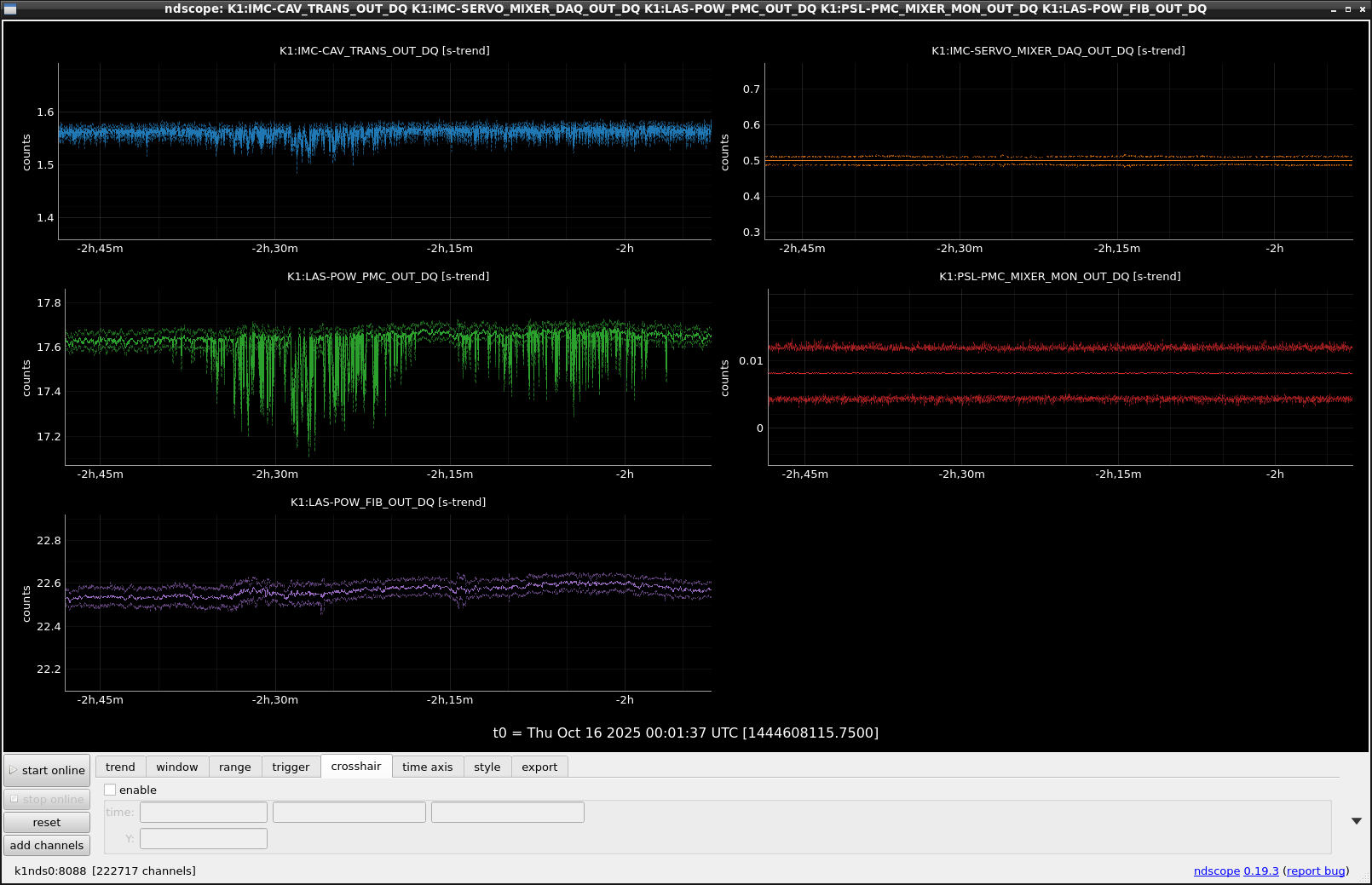
We will leave the IMC locked overnight to monitor stability.
---
## What We Did
### PMC Lock with ~20 W from the Fiber Output
The PMC was successfully locked with 1 W output yesterday. However, a TEM00-like mode was visible in the PMC REFL camera even though the PMC was locked to TEM00 (Fig. 1). We realized we had forgotten that we removed the 20 dB attenuator between the RF LO and the EOM for PMC during a previous investigation into NeoLASE frequency noise (klog34997). As a result, the modulation index was ~10× higher than in the previous setup. After reinstalling the attenuator, the TEM00-like mode in the REFL camera disappeared. Thus, the observed TEM00 mode was actually the RF sideband, not the carrier.
Next, we used an IR viewer to inspect the beam path from the black box output to the PMC with 1 W input. The beam spot appeared centered on each optic. We then increased the power to 20 W and finely aligned the PMC input axis using pico motors. Figure 2 shows the REFL and TRANS camera images after fine alignment. An LG mode appears dominant in the REFL image, suggesting that mode matching may need improvement.
We also adjusted the fiber output so that the PMC transmission reached ~17 W, required to deliver ~10 W into the IMC.
We measured the PMC OLTF and tuned the servo's common gain to achieve a UGF of ~3 kHz. Figure 3 shows the measured OLTF.
(Note: I had forgotten that the gain from OUT1 to OUT2 is 10 dB, so the actual UGF corresponds to the –10 dB crossing point. The UGF measured yesterday might have been >4 kHz.)
We updated the PMC guardian script accordingly.
We then measured the frequency noise following the same procedure as in klog35280, now with 20 W output. Figure 4 shows the results:
- **Red**: Fiber amp. @ 20 W
- **Blue**: NeoLASE @ 20 W
- **Green**: Fiber amp. @ 1 W
Above 1 kHz, the red curve shows lower noise than both the blue and green. The reason is unclear, but this result supports using the fiber amp. at 20 W.
---
### PLL Lock
After locking the PMC, we tuned the IR and GR temperatures for PLL locking. However, both PLLs were already locked without adjustment. Possibly, the IR laser's absolute frequency at 1.1 A coincided with those of the GR lasers. In any case, we left the PLLs untouched.
We measured the PLL OLTFs.
Figure 5 shows the results:
- Bright curve: PLL-Y
- Dark curve: PLL-X
Both have UGFs around 20 kHz, consistent with klog35144.
---
### IMC Lock
Finally, we attempted to lock the IMC. Before locking, we modified the feedback paths:
- PZT path: Connected directly to laser PZT, removing the 150 kHz notch filter and 20 dB attenuator.
- EOM path: Connected directly to the fiber broadband EOM, removing the HV amplifiers.
This configuration matches the previous one used with the fiber amp. laser.
We then requested the IO guardian to enter the `IMC_LSC_LOCKED` state without changes. The IMC locked, but the normalized transmission power was low, and the IMC TRANS beam spot flickered. After adjusting the IMC CMS common gain, the normalized transmission returned to ~1.
We then measured the IMC OLTF (Fig. 6) and the crossover frequency between EOM and PZT.
- UGF: 120 kHz
- Crossover frequency: 10 kHz
We adjusted FASTGAIN of IMC CMS to set the cross-over frequency to 14 kHz. We noticed structures around 150 kHz in both TFs. To investigate, we inserted an SR560 in the PZT path and tested different LPFs:
- Common settings: DC coupling, ×1 gain
Fig. 7 shows.the TF between the EOM loop and the PZT loop:
- Bright curve: 2nd-order LPF @ 100 kHz
- Dark curve: 1st-order LPF @ 30 kHz
The 30 kHz LPF provided better roll-off and a sufficient phase margin, so we adopted this configuration.
We remeasured the IMC OLTF. Figure 8 shows the final result—the 150 kHz structure disappeared. We then adjusted the common gain so that the IMC loop's UGF became **160 kHz**. This improvement should allow us to increase the CARM UGF in future steps.
---
We will keep the IMC locked overnight to monitor the stability of the current setup.


