Ikeda, Tanaka
## Abstract
RF related signals seem to be not guilty. But the connection seems to be somehow nonsensical. When noise increases at a certain frequency, it was confirmed that the noise actually increases at that frequency because there seems to be no strange oscillation peaks in high-frequency region even though the signals in low frequency region around 1 kHz got 10 times larger. From these results, we need to investigate Laser source itself.
## What we did
### related RF
Yesterday, Ushiba-san concerned about RF amp. output. According to Ushiba-san, in general, RF amp. output signal is mush noisy than RF input signal for some reason (add harmonics, etc.,). Also, Miyoki-san concerned that there is something wrong with the RF oscillator itself.
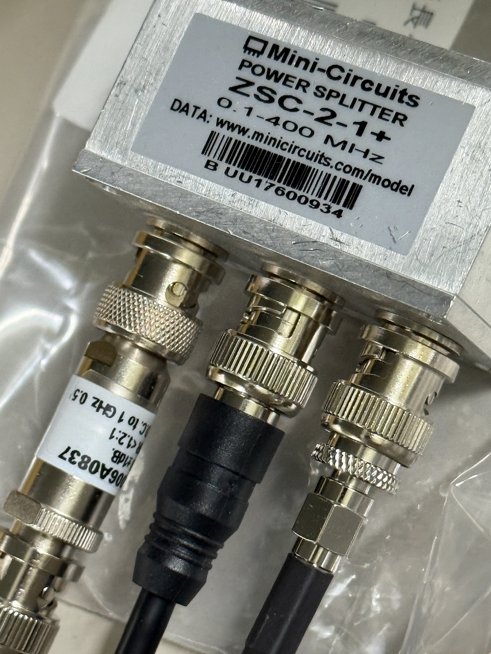
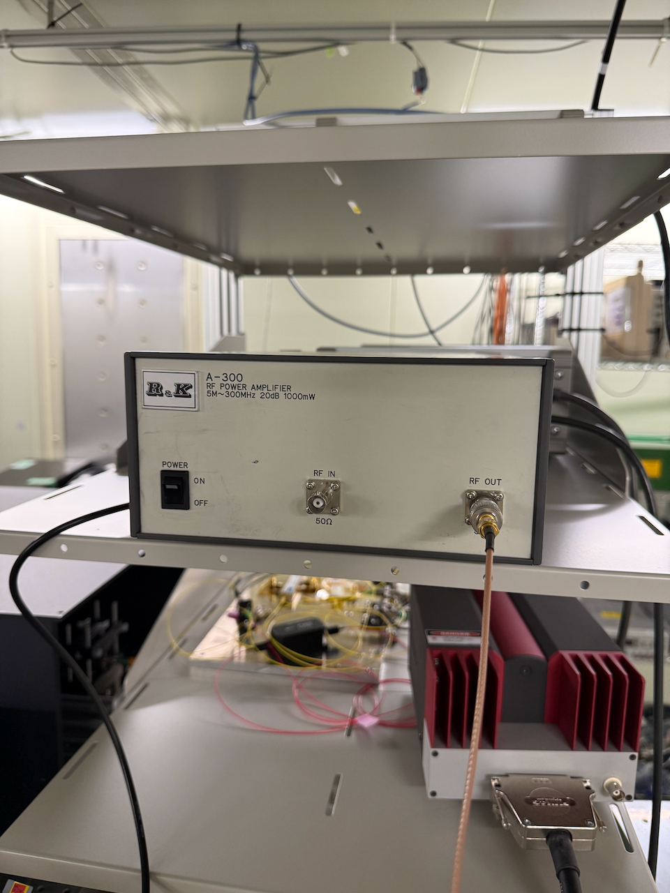
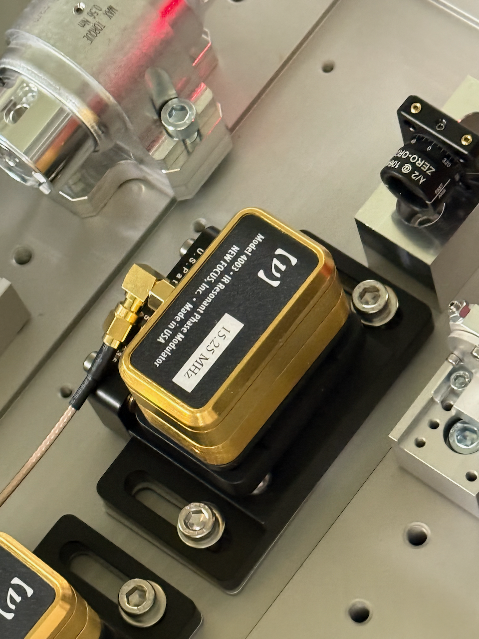
So we checked some signals around the RF connection. And we found that current RF signals flows from LO to EOM is as follows; oscillator -> power splitter (mini circuits, ZSC-2-1+, fig.1) -> 20dB attenuator (telegartner, J01006A0837, fig.1) -> 20dB amp. (R & K, A-300, fig.2) -> EOM (NewFocus, 4003, fig.3). I'm not sure the reason why the RF signal is attenuated before amplifying. Anyway, we tried to measure the RF power at some points. Moku:lab seems to be able to measure the RF power by 24 dBm (10 Vpp, 50 Ohm setting) so we input the RF signals to Moku's input port directly when we measure the RF power.
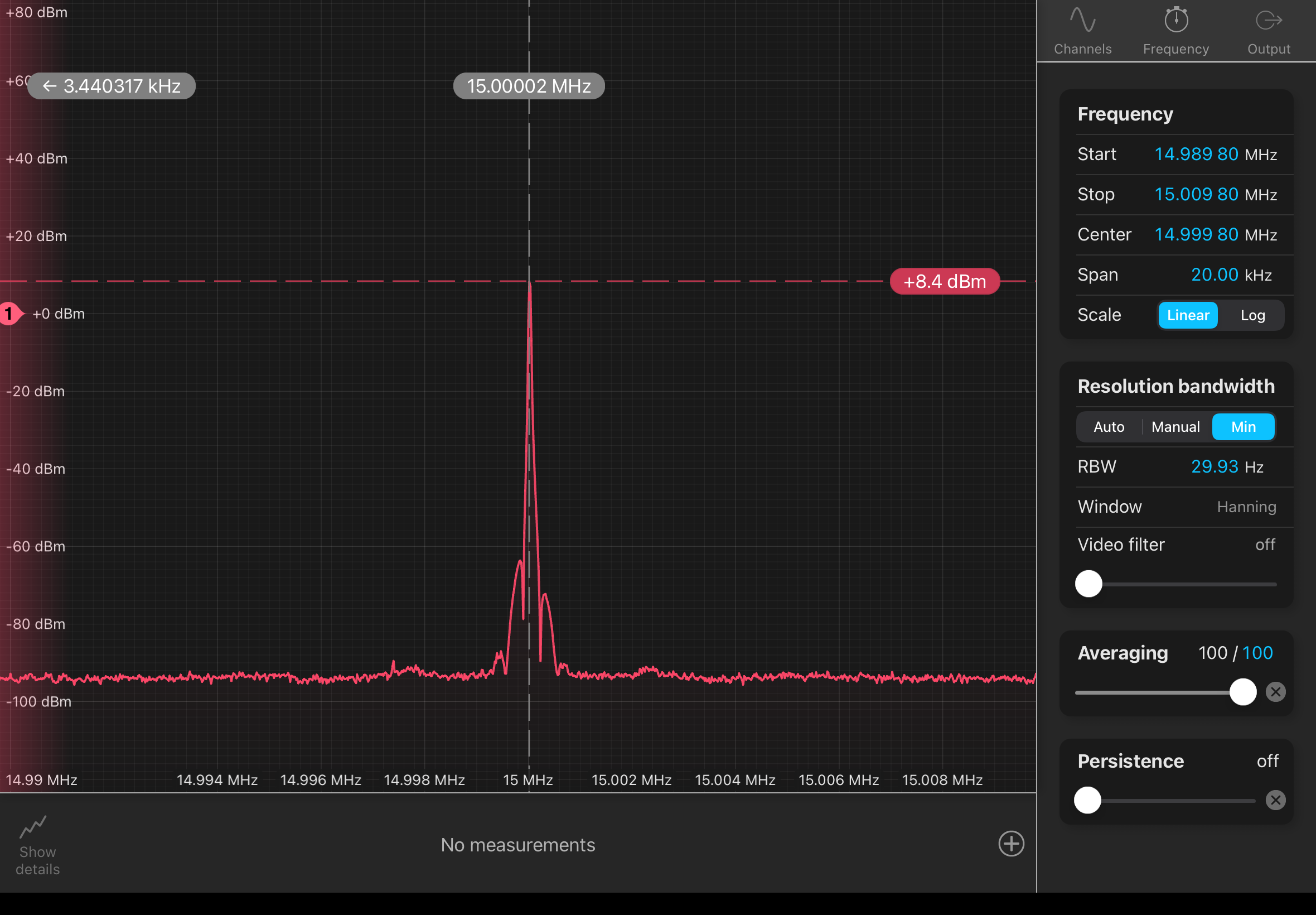
Fig.4 shows the RF signal spectrum just after the oscillator output port. According to the lable in front panel of the oscillator, the nominal frequency is 15 MHz and the amplitude 8.6 dBm. the measured RF power is ~8.4 dBm at ~15 MHz and seems to be consistent with the nominal value written in the label. There seems to be two sideband peaks apart from +/- 0.355 MHz but no significant noise.
Fig.5 shows the RF signal spectrum just before the RF amp, which is passed thourgh the power splitter and the 20dB attenuator. The measured RF power is about -15.2dBm and is almost consistent with 8.4dBm - 3dB (power splitter) - 20dB (attenuator) = 14.6 dBm.
Fig. 6 shows the RF signal spectrum after the RF amp. output. The measured RF power is 4.7 dBm and is almost consistent with -15.2 dBm + 20 dB (RF amp) = 4.8 dBm. Also, there seems to be some hormonics in the RF amp. output (fig.7) but their amplitudes are less than -40 dBm. Therefore, there seems to be no signifcantly strange point in the RF amp. output. I think we should remove the RF amp. and the attenuator and input the RF signal from the power splitter to EOM directly rather than the Band pass filter is inserted between the RF amp. and the EOM to remove their harmonics.
At last, EOM frequency seems to be tuned to 15.25 MHz but the LO frequency is just 15 MHz. So we changed the LO frequency to 15.25 MHz and will check the situation is changed or not.
### PMC error/feedback signals in high-frequency region (> 8 kHz)
We connected the COMMON OUT1 port and the FAST OUT2 port of the TTFSS servo with Moku IN1 and IN2 respectively to measure the spectra of the PMC error/feedback signals above DGS Nyqust frequency (8 kHz). There seems to be no strange oscillation peaks in high-frequency region even though the signals in low frequency region around 1 kHz got 10 times larger (fig.8). When noise increases at a certain frequency, it was confirmed that the noise actually increases at that frequency.
### increase PMC LSC control gain to 10dB
Tonight, I'll try increasing the PMC control gain by about 10dB and leave it like that. This is because the PMC's UGF was 5kHz with the original laser (klog22620), whereas with the current laser, it's only 2kHz (klog34872).
From above results, we need to investigate Laser source itself.


