[Fujimoto, Ye, Saito]
To investigate whether the splitting of the peak observed in the previous measurement (klog:37440) was caused by mode splitting due to birefringence of the ITM substrate, we used an HWP and a PBS to separate the light into S- and P-polarizations and installed PDs to monitor the two signals. When we performed cavity scans using only the main laser or only the sub-laser, we confirmed that the resonance positions of the cavity scans were different between S- and P-polarizations in both cases. Therefore, we consider that the splitting of the peak was caused by mode splitting due to birefringence of the ITM substrate.
- In the previous measurement (klog:37440), to investigate whether the splitting of the peak was caused by mode splitting due to birefringence of the ITM substrate, we placed an additional mirror after the mirror at the reflection port of OMMT2. We then placed an HWP and a PBS after this mirror and installed two PDs to monitor both the reflected and transmitted light from the PBS (Photo 1).
- Next, we rotated the HWP so that the transmitted and reflected powers from the PBS were approximately equal. The scale reading was 56, and both powers were approximately 0.7 mW. This scale reading was similar to the value obtained when the polarization was rotated by 45 degrees in the previous measurement (klog:37440).
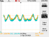
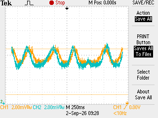
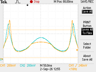
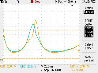
- We then turned off the main laser, removed the ND filter, and injected only the sub-laser in the S-polarization state. By sweeping the PZT with a triangular waveform, we confirmed that the resonance positions of the cavity scans were different between S- and P-polarizations (Photo 2). The orange line in Photo 2 shows the S-polarization signal, while the blue line shows the P-polarization signal. Since the relative shift reverses at the turning points of the triangular waveform, we consider that this is caused by mode splitting due to birefringence of the ITM substrate.
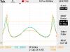
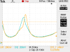
- Next, we turned off the sub-laser and used only the main laser. When we swept the SRM, we similarly observed a difference in the resonance positions between S- and P-polarizations (Photo 3). However, near each peak, the other polarization signal became smaller (Photo 4), suggesting that the S- and P-polarizations were not completely separated. We therefore rotated the HWP to see whether the two polarizations could be separated more completely, but there was no improvement. Therefore, the light appears to be elliptically polarized. The reason why this behavior was not observed when using the sub-laser is likely that the SNR was too low.