[Fujimoto, Saito]
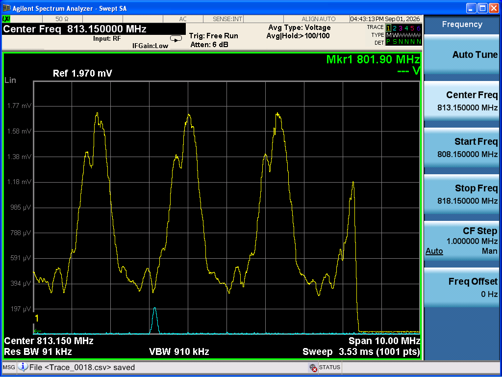
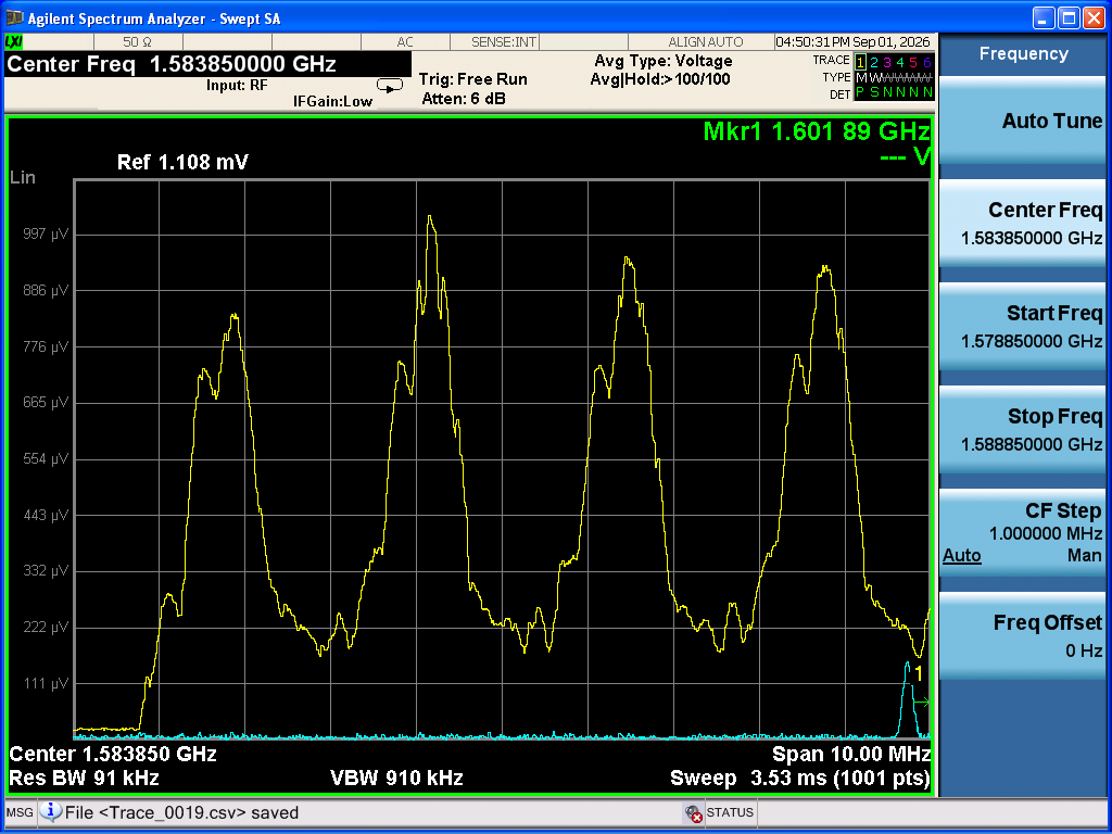
The issue of the low DC output from the RFPD reported previously (klog:37436) was resolved by reconnecting the cable. Next, an HWP was installed in front of the BS for the sub-laser, and the polarization was set to S-polarization. When the beat signal was observed, the peak was split into two. By rotating either the HWP in front of the BS or the polarizer in front of the RFPD, the relative amplitudes of the two peaks could be changed. Therefore, it appears that the P-polarization peak is also being observed simultaneously, and this is likely caused by birefringence in ITMY. The results of determining the SRY length from the beat signal data acquired while maximizing each of the two peaks will be posted later.
- First, to investigate the reason for the low DC output from the RFPD reported previously (klog:37436), we monitored the DC output of the RFPD with an oscilloscope and found it to be approximately 8 V. Since there was no problem with the signal amplitude and the fluctuations were not significant, we reconnected the RFPD to CDS, and the DC output was approximately 12500 counts, corresponding to approximately 7.6 V. Therefore, the connection may not have been good in the previous measurement (klog:37436).
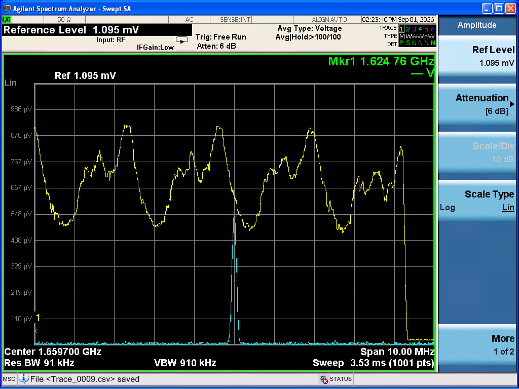
- Next, an HWP was installed in front of the BS for the sub-laser (Photo 1), and the polarization was set to S-polarization using a PBS. The main laser was then turned off, and the sub-laser was aligned to SRY. When we observed the beat signal at -1.6 GHz, the peak was split into two (Photo 2). We then rotated the polarizer in front of the RFPD. This allowed us to decrease the amplitude of one peak while increasing that of the other. Similarly, rotating the HWP installed in front of the BS also allowed us to change the relative amplitudes of the two peaks. Therefore, although the sub-laser was initially set to S-polarization, the measured beat signal contains a P-polarization component. This is likely due to birefringence in ITMY.
-
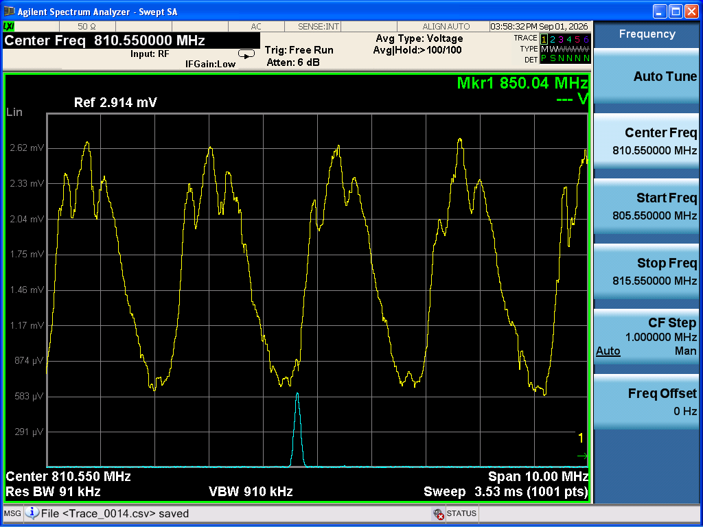
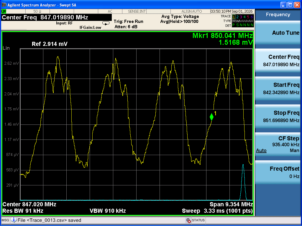
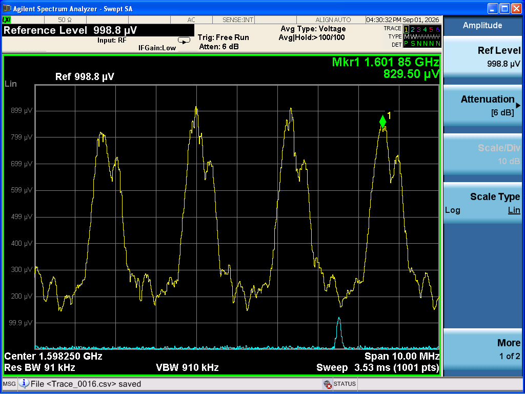
When the measurement was first performed with S-polarization, the HWP setting was 82. By changing the HWP setting to 14 and the polarizer setting in front of the RFPD to 295, we were able to maximize the peak that was smaller in the initial S-polarization measurement. We then acquired data at beat frequencies of 1.6 GHz (Photo 3), 0.8 GHz (Photo 4), -0.8 GHz (Photo 5), and -1.6 GHz (Photo 6). Next, we set the HWP to 59 and the polarizer in front of the RFPD to 250, which allowed us to maximize the other peak. We then acquired data in the same way at beat frequencies of 1.6 GHz (Photo 7), 0.8 GHz (Photo 8), -0.8 GHz (Photo 9), and -1.6 GHz (Photo 10). The amplitudes of the beat signals when each peak was maximized were approximately 931 μV for the peak that was larger in the initial S-polarization measurement and approximately 1.46 mV for the peak that was smaller. Thus, the two peak amplitudes differed by a factor of approximately 1.57. In addition, when the HWP setting was 14, we checked the polarization of the sub-laser using a PBS. The measured powers were approximately 476 mW for P-polarization and 513 mW for S-polarization. Finally, we removed the HWP, but the beat signal was still split into two peaks, similar to the observation in Photo 2.
The result of determining the SRY length from the data analysis will be posted later.