[Kawaguchi, Sugimoto, Michimura, Fujimoto]
Abstract
On 12/1, we performed a calibration of the polarization monitor system at TMS-X (klog #30113).
The purpose of this calibration was to obtain the calibration factor for converting the p-pol PD spectrum (V/rtHz measured by DL950, cnt/rtHz measured by CDS) into the polarization rotation spectrum (rad/rtHz).
In addition, the polarization state (ellipticity) of the cavity transmitted light was measured at the same time.
Preparation: Dark offsets of PDs
We measured the output offsets of each PD in the polarization monitor system using both the DL950 and CDS.
For CDS, we used the channels K1:TMS-X_IR_PDA1_OUT_DQ, K1:TMS-X_IRSPOL_PDA1_OUT_DQ, and K1:TMS-X_IRPPOL_PDA1_OUT_DQ.
Note that CDS internally adds offsets before the dewhitening filter (after the ADC).
DL950 CDS
X_IR -5(1)e-3 V -0.3(2) cnt
X_IRSPOL 3(1)e-3 V -10.24(3) cnt
Y_IRPPOL 15(1)e-3 V 0.04(7) cnt
Calibration: p-pol PD to polarization rotation (V/rtHz → rad/rtHz)
We rotated the HWP in the polarization monitor system and measured the output voltages of the p-pol PD and s-pol PD with the DL950.
During the measurement, the average output of the X_IR PD was 3.79(3) V.
Figure 1 shows the measurement results, where the vertical axis is the measured voltage after subtracting the PD offsets, and the horizontal axis is the HWP scale value.
We fitted the data using the following model:
Model:
Fitting parameters: A [V], B [deg], C [V]
Result:
A = 4.10(5) V
B = 8.2(2) deg
C = 0.64(2) V
From this, the calibration factor for converting the p-pol PD spectrum (V/rtHz) to polarization rotation (rad/rtHz), where the HWP scale is and the X_IR PD output is , is obtained as
Calibration factor:
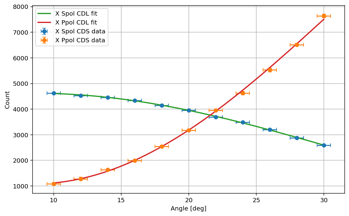
Calibration: p-pol PD to polarization rotation (cnt/rtHz → rad/rtHz)
During the measurement above, we also recorded data with CDS with the unit of cnt.
The average count of the X_IR PD during the measurement was 3.17(2)e3 cnt.
Figure 2 shows the measurement results, where the vertical axis is the measured count after subtracting the offsets, and the horizontal axis is the HWP scale.
We fitted the data using the model:
Model:
Fitting parameters: A [cnt], B [deg], C [cnt]
Result:
A = 6.9(1)e3 cnt
B = 8.5(3) deg
C = 1.08(4) cnt
From this, the calibration factor for converting the p-pol PD spectrum (cnt/rtHz) to polarization rotation (rad/rtHz), where the HWP scale is and the X_IR PD output is , is obtained as
Calibration factor:
Polarization ellipticity
For reference, the ellipticity (semi-minor/semi-major axis) of the polarization incident to the polarization monitor system can be estimated as
Ellipticity = sqrt(V_p_min/V_p_max)=sqrt(C/(2*A+C))=0.270(5)
Since the transmitted beam from the ETM passes through multiple steering mirrors before reaching the polarization monitor system, it is highly likely that the polarization acquires ellipticity along the optical path.
Nevertheless, the above value gives an upper limit on the ellipticity of the cavity transmitted light.
Next
We will perform a similar analysis for the calibration measurements at TMS-Y polarization monitor system conducted on 12/2.
Using these calibration results, we will convert the measured p-pol PD spectra into polarization rotation spectra.

