Ushiba, Tanaka
work from the night on 2025.3.10 - the moring on 2025.3.11
## Abstract
We succeeded in implementing OMC ASC with beacon and The ASC seems to work well. This time, OMC ASC setpoints are zero but we have not confirmed whether this setpoints are optimal in terms of the sensitivity yet.
## What we did
- We performed the following work with LOCKING_OMC_FOR_PRFPMI, that is, the input power was 10W and PRFPMI RF locked with ASC.
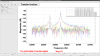
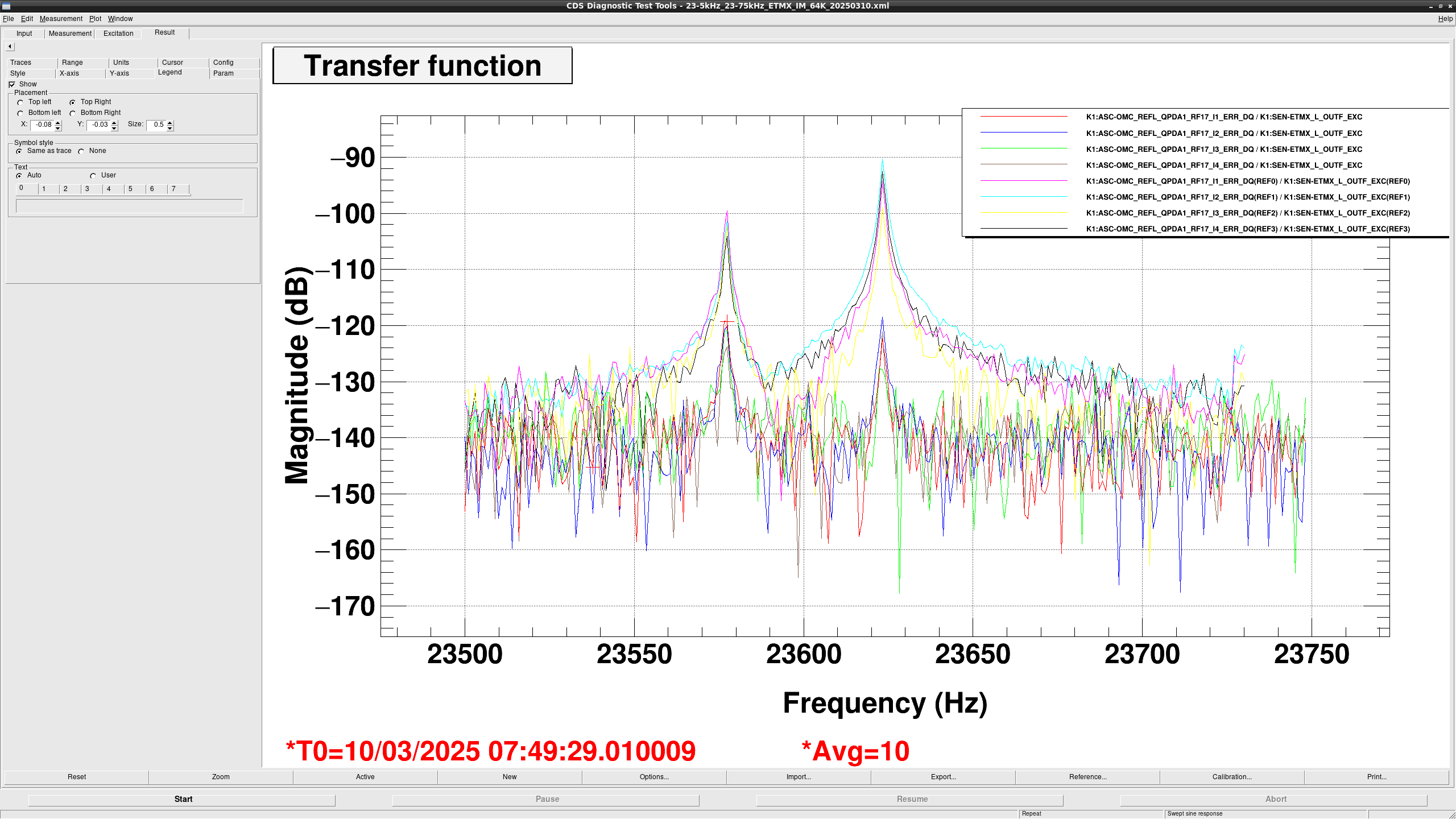
- First, we scaned ETMX to search the drumhead mode frequency at the EX current temperature (~64K). As reported the original post, we found the 2 peaks around the drumhead mode frequency. Accoriding to Kaihotsu-kun's Master thesis (JGWdoc), one is the fundamental drumhead mode (fig.C.8 in his thesis) and the other is the TEM01 like mode (fig.C.7 in his thesis). Previously, we considered the higher frequency one is the drumhead mode because his simulation result said so. This time, In order to identify the mode, we scaned ETMX witth only horizontal coils (H3 and H4) because the horizontal coils are close to the node of the TEM01 like mode. So we considered one of the peak height became smaller. Fig. 1 shows the scan results before and after reducing the number of excitation coils. The curves labled "REF" are the siganls in OMC_REFL_QPDA1_RF17_I_SEG1_IN1_DQ with 4 coils and the curves without any labels are the ones with the only 2 horizontal coils. The height of the lower frequency one got smaller to 20dB. On the other hand, the height of the higher frequency one got smaller to 30dB. From this results, we consider the lower one is the drumhead mode. This time, we used the lower frequency one.
- One of possibilites is that each 24 kHz excitation phase at each coil from DGS may not align by the steep phase shift of AI filter at 24 kHz. This is the reason why we can excite the TEM01 mode when we injected the excitation to 4 coils commonly. Anyway we need the method to identify the mode.
- Second, we tuned the frequency to 23.577 kHz and tuned the excition amplitude to 3000 cnts.
- Then, we performed the phasing for RF17 to minimize each Q signal (K1:ASC-OMC_REFL_QPDA{1,2}_RF17_Q{1,2,3,4}_ERR) of the 24 kHz from each QPD with the same procedure (klog32592).
- After that, we rotated the 24 kHz demod. phase to minimize the Q signal (K1:ASC-OMC_REFL_QPDA{1,2}_SEG{1,2,3,4}_DEMOD_Q_IN1) when we excited OMMT2 PIT at 3.125 Hz (like klog31226).
- We decoupled the OMMT2 and OSTM PIT/YAW motions using 0.5 Hz excitation.
- We tuned the UGF for Yaw loops to 0.2 Hz and the UGF for PIT loops for 0.1 Hz and then closed the loops. The lock duration seems to be 30 mins and the fluctuation of K1:OMC-TRANS_DC_SUM_OUT_DQ seems to be smaller. (fig.2)
- This ASC is engaged by the OMC_ASC guardian automatically when LSC_LOCK is LOCKING_OMC_FOR_PRFPMI.