Ushiba, Dan, Tanaka
## Abstract
We tried to recover OMC ASC to stabilize the alignment to OMC. Before the recovery, we performed the demodulation phasing of the beacon frequency using the 0.5 Hz excitation of OMMT2 PIT. After that, we made the sensing matrix for OMC ASC. Then, we tried to close the loops, and we succeeded in keeping the current alignment, but we did not achieve the control with the zero setpoint because the Y2P coupling of OMMT2 seemed to be too bad. So we will balance the OMMT2 actuator tomorrow.
## What we did
- According to klog31209, Ushiba-san already performed the phasing using just a reflection beam from OMC when OMC was not locked. Using this and the previous matrix, we closed the loops of OMC ASC but the ASC seemed to make the alignment bad. After that, we noticed the results of phasing was different whether OMC was locked or not. So we started to review the procedure from the phasing one by one.
- First, we confirmed the reproducibility of the phasing result. we found that the result seemed to be reproducible when OMC was not locked. On the other hand, the results were different whenever OMC was locked. Moreover, the amount of the value shift was different among each segment. Then, we found the RF17 demodulated signals occurred the saturation by 15 Hz alignment fluctuation due to SR3 ADS. So we decreased the SR3 ADS modulation amplitude to 1/10. we could avoid the saturation. After that, we tried the phasing with 16.125 Hz excitation of OMMT2 PIT at first. However, the SNR seemed to be too bad to perform the phasing even though the excitation oscillated the OMC transmitted power. So we changed the excitation frequency to 0.5 Hz and measured the ratio between I and Q signals after the 24 kHz demodulation. Then, we obtain the demodulation phase from the measurements. The measurement files are in /users/Commissioning/data/ASC/2024/1007. By the way, we noticed that the sign of the signal after the 24 kHz demodulation was decided by the demodulation phase. So the signs of the quadrant signals on the upper side of QPD should be opposite to the ones on the lower side when we perform the phasing using the PIT signal. So we decided on the demodulation phase so that each sign from SEG1 and SEG2 is positive, but each phase from SEG3 and SEG4 is negative.
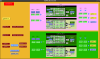
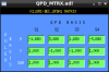
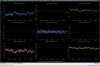
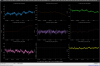
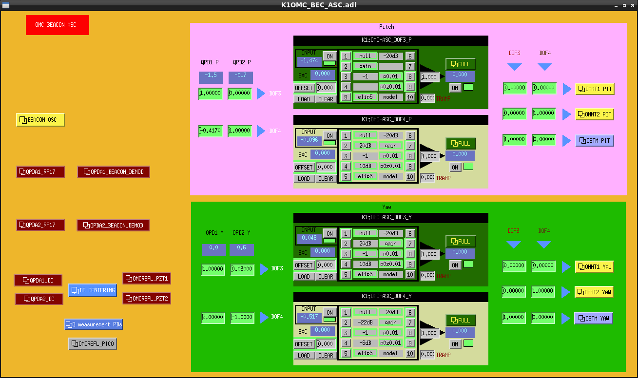
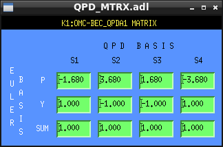
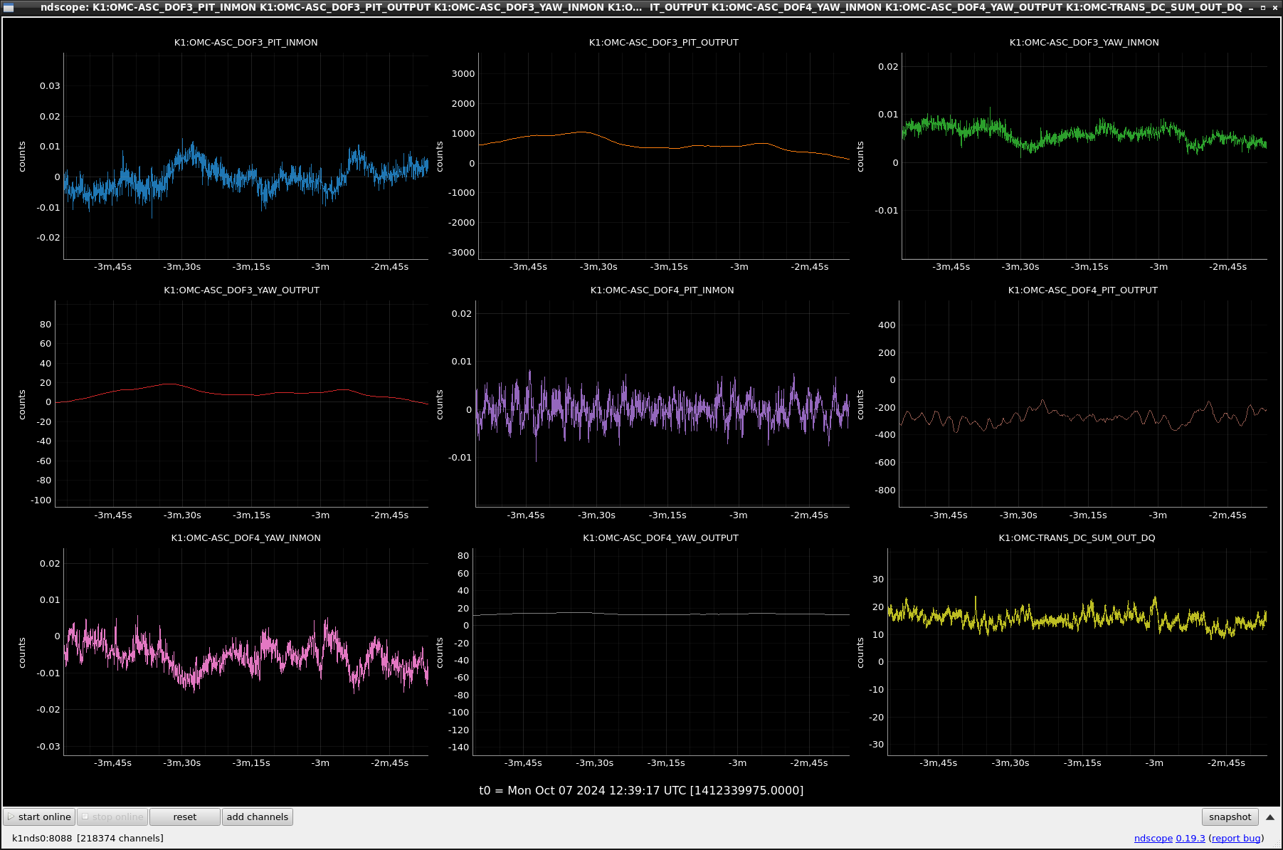
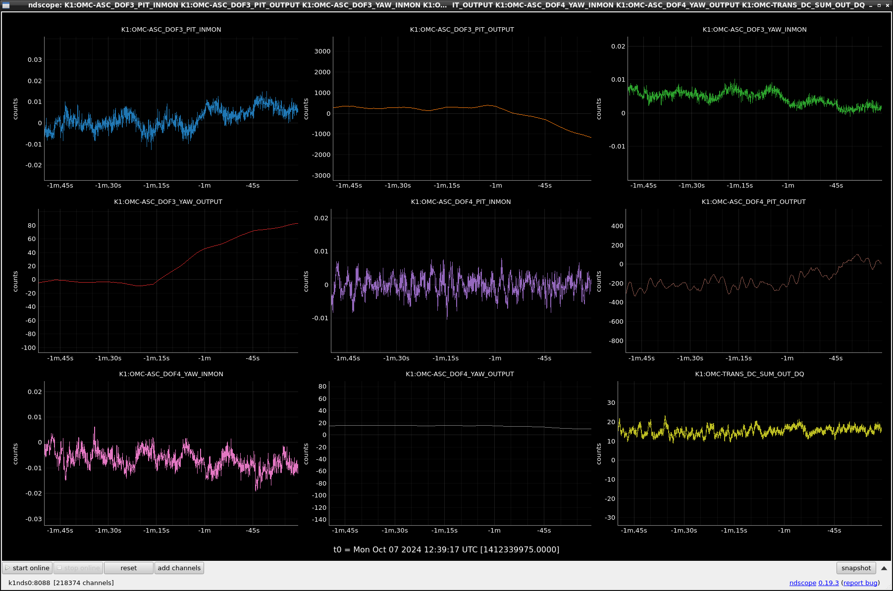
- Second, we decoupled the DoFs of OMC ASC using the 0.5Hz excitation, (DOF3 -> OSTM, DOF4 -> OMMT2). Fig. 1 shows the decoupled input matrix. After the decoupling, we closed the loop. OSTM PIT/YAW error signals started to move the zero setpoint at first but they stopped on the way even if the feedback signals increased and the transmitted power decreased. So we measured the coupling between PIT and YAW. The couple from PIT to YAW of OSTM seems not to be bad, but the couple from YAW to PIT seems to be too large (x2.68). As for OMMT2, the couples seem not to be bad. So the OSTM itself has a large Y2P coupling. We tried to compensate for the coupling by adjusting the SEG2EUR matrix of QPD1 (fig.2) (because QPD1 is more sensitive about OSTM motion than QPD2.) In this state, we closed the OSTM loops with the offsets in the setpoint to keep the current alignment (fig.3). The ASC seems to keep the alignment. but we turned off the offset, the PIT and YAW alignment got crazy (fig.4). So we will balance the OMMT2 actuator tomorrow.