[Haoyu Wang, Yuta Michimura]
We found that f1 sideband and 1st higher order mode are very close and overlapping in the arm cavities.
There might be some effects in ASC.
(I'm not sure if this is known or not...)
Background:
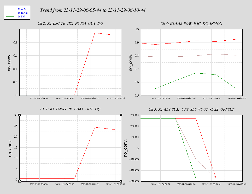
- As a preparation for the arm cavity round-trip loss measurement, we did the arm cavity scan to check the mode-matching (klog #30823).
- We found that the sideband locations were consistent with Hirose+ measurement in Nov 2023 (klog #27767), but not with Enomoto+ measurements in Dec 2018 (klog #7332 and klog #7307)
What we did:
- After aligning Xarm, we intentionally misaligned ETMX in YAW (changed K1:VIS-ETMX_TM_SET_Y_OFFSET=-18 to -22) so that we can see higher order modes better.
- Scanned Xarm following the same steps we took last night (klog #30823).
Results:
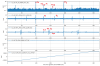
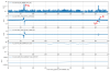
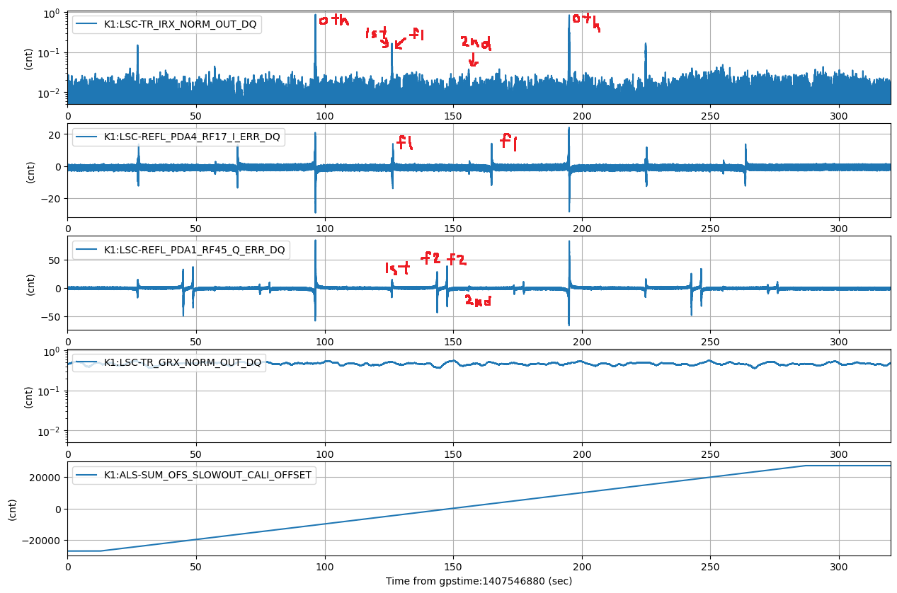
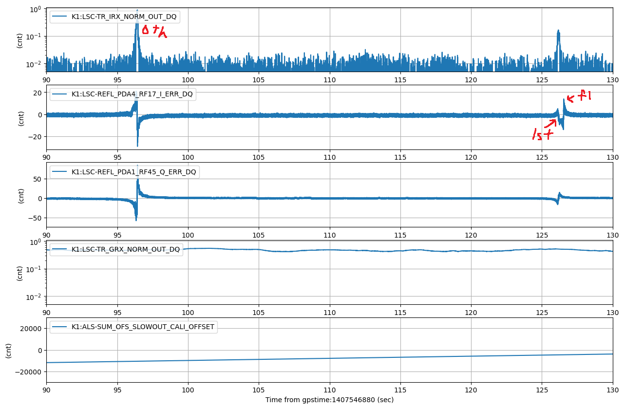
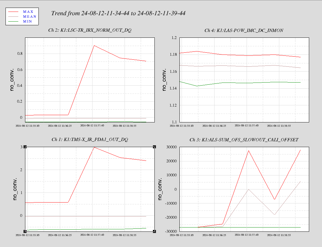
- Attachement #1 shows the result of the Xarm cavity scan. 1st and 2nd higher order modes can be clearly seen from the error signals and transmission peaks. f1 sideband and 1st higher order mode are overlapped (see Attachment #2 for the zoomed in view).
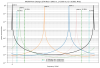
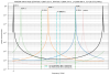
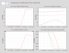
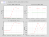
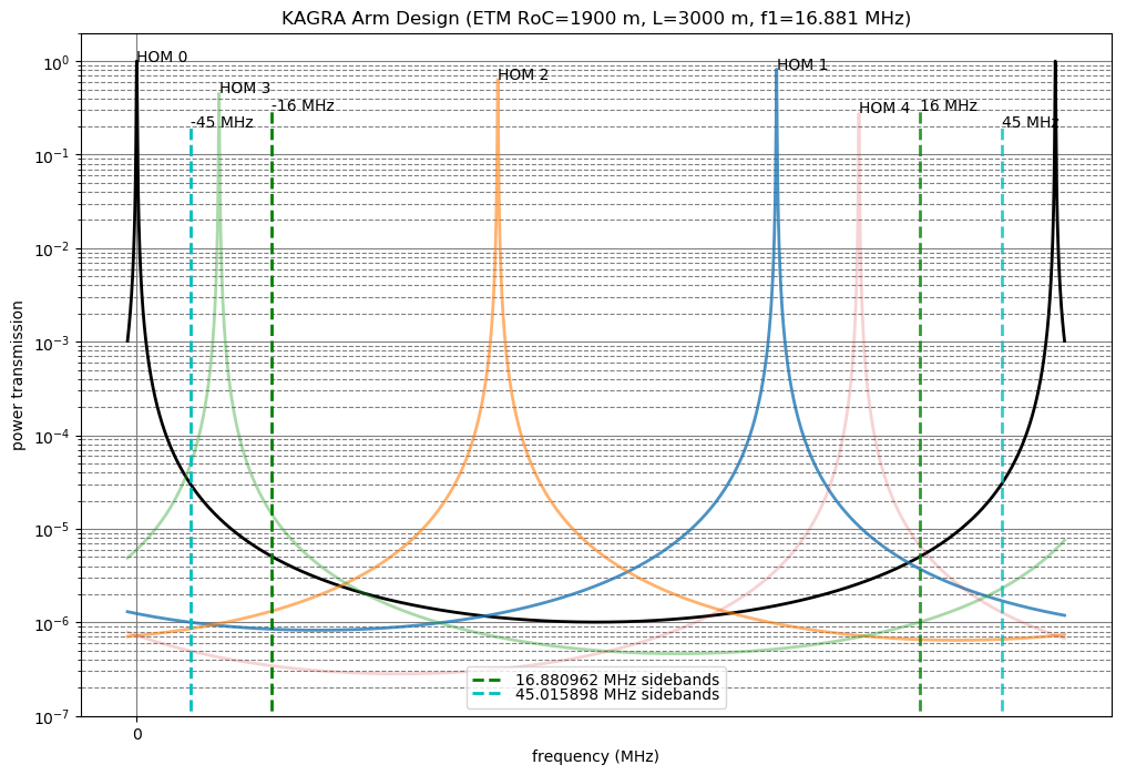
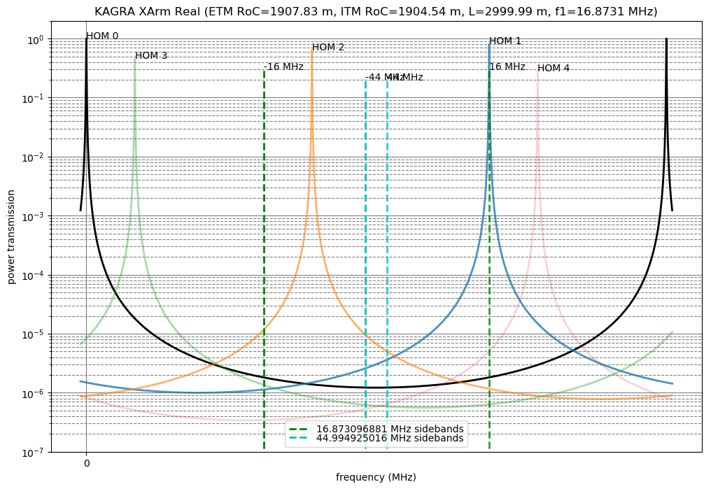
- In the original design, f1 and f2 sidebands are located in between 0th and 1st order modes (Attachment #3), but if we use the measured values, HOM1 and f1 are overlapped (Attachment #4), explaining the current situation. Table below are the list of parameters used to calculate these mode spacing plots.
| Design (see OptParam wiki page) | Measured (individually) | |
| Arm length | 3000 m | 2999.990(2) m (klog #7332; could be old) |
| ITM RoC | 1900 m | 1904.54 +/- 2.08 m (PhysRevApplied.14.014021) |
| ETM RoC | 1900 m | 1907.83 +/- 2.14 m (PhysRevApplied.14.014021) |
| f1 sideband frequency | 16.880962 MHz | 5.624365627 MHz *3 (klog #30092) |
| f2 sideband frequency | 45.015898 MHz | 5.624365627 MHz *8 (klog #30092) |
Note:
- We confirmed that the mode-matching is pretty good when aligned.
- Compared with the measurement in Nov 2023 (klog #27767), K1:LSC-TR_IRX_NORM_OUT_DQ seems noisy, and this is preventing us from seeing sideband beaks in the transmission. Not sure why it is noisier now (Different PD gains and/or whitening gains? Notch filters?).
Next:
- We might need to tune IMC length and PRC length to shift the sideband frequencies.