[Ushiba, kTanaka, Hirose]
We measured demodulation depth with x-arm cavity scan. I seem the peaks of sideband f1, f2 but not sideband f3. The f3 sideband peak may be buried in noise, but we need to check if the EOM is connected in the first place. (We confirm that it is connected from LO to f3 RFamp, we need to check if the cable is connected from RFampf3 to EOM).
Prepared steps:
- LSC_guardian is "DOWN" state, Type-A suspensition is "misaligned" state, and PRM mirror is "misalign-BF" state.
- Engaged green lock in Xarm.
- When confirmed Green laser lock in Xarm, Put gain 1 as soon as possible.
- According to "ENGAGED_ALS_CARM" state in "LSC_LOCK" guardian,
- Turn on "FM4" in FILT_MCL.
- Turn on "IN2" in CMS(Common mord survo) IMC survo.
- Turn off "FM2" in FILT_MCL.
- Change "IN2" gain to 24 in CMS_CARM survo.
- Turn on "COMBOOST" in CMS_CARM survo.
- Turn on "FM5" in FILT_MCL.
- Turned HWP from 4deg to total 37deg. 37deg seems to be the top of the power.
(Now, when PSLHWP reaches a certain value, we have to manually turn down the gain of INP2 by 1deg before turning the next 1deg. After turning HWP by 1deg , we have to manually turn back the gain of INP2. In this case we did this process at 9deg and 22deg) - The SUMMING SURBO offset was swept from -27000 to 27000 at 300 seconds.
Results:
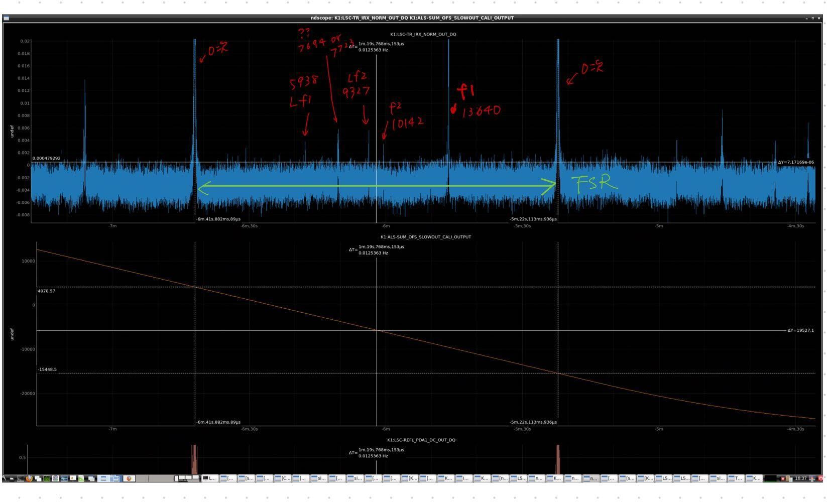
- For the distance (FSR) between the two peaks flushing at the zeroth order, we find that swept about 19527 counts. According FSR result, it was swept at about 0.39[Hz/cts].
- The seed frequency of the local oscillator is 5.624371MHz.
If 5.624371MHz is tripled f1, octupled f2, and multiplied by 10 f3, the following equation is obtained.
- Based on the counts of the FSR offsets, we predicted where the sidebands would peak. If the peak was actually close to that location, the count number of that peak was recorded.(Fig1, Fig2)
caluculation count parameter mesurement count parameter upper f1 13588[cnts] 13640[cnts] upper f2 10199[cnts] 10142[cnts] upper f3 12749[cnts] None lower f1 5938[cnts] 5902[cnts] lower f2 9327[cnts] 9355[cnts] lower f3 6777[cnts] None We could not find the peak of sideband f3. We don't know if it is not visible due to noise or if the signal is not coming to the EOM. We need to investigate.
This is the priminary result. The modulation indexes and other information will be summarized at a later date. - According to Yamamoto-san's master's thesis, the modulation indexes for f1, f2 and f3 were 1.68, 1.68 and 0.05.
The f2 peak was small so f3 might not be visible due to noise.