Reports 1-1 of 1 Clear search Modify search
MIF (ITF Control)
kenta.tanaka - 21:02 Monday 17 June 2024 (29949) Print this report
MICH lock trial

[Dan, Yuzurihara, Tanaka]

## Abstract

We tried and succeeded in the MICH lock with both the 3f and 1f signals without the change of ITMY alignment. The open loop gain of 3f MICH seems reasonable because the contrast is 10% lower than the previous one. However, the open loop gain of 1f MICH is 8 dB lower than the previous one. We're not sure the reason why for now (ITMY alignment?, clipping on POP table?). So we need more investigation.

## What we did

  • First, we aligned BS with the current ITMY alignment to hit the beam on REFL PD. (Note that ITMY alignment may not be best because GRY flash was not confirmed for some reason, but not so bad because GR beam reached 3 km with current ITMY alignment.) We aligned ITMY and BS, misaligned ITMX with each guardian, then we roughly oscillated BS IM stage in both P and Y degrees of freedom with IM OPTICALIGN (+/- 1000 cnts) and found the flash on REFL PD at some alignment. We adjusted BS to that alignment and tuned the BS alignment to maximize the power on the REFL PD manually.
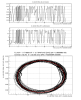
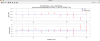
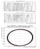
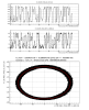
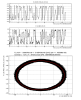
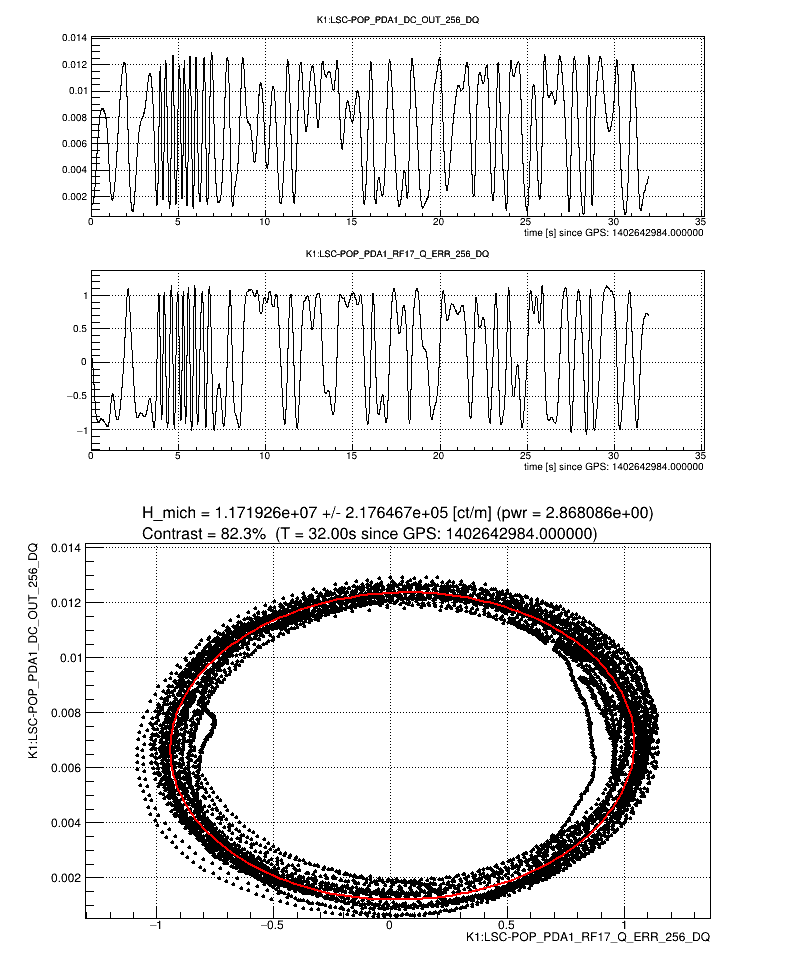
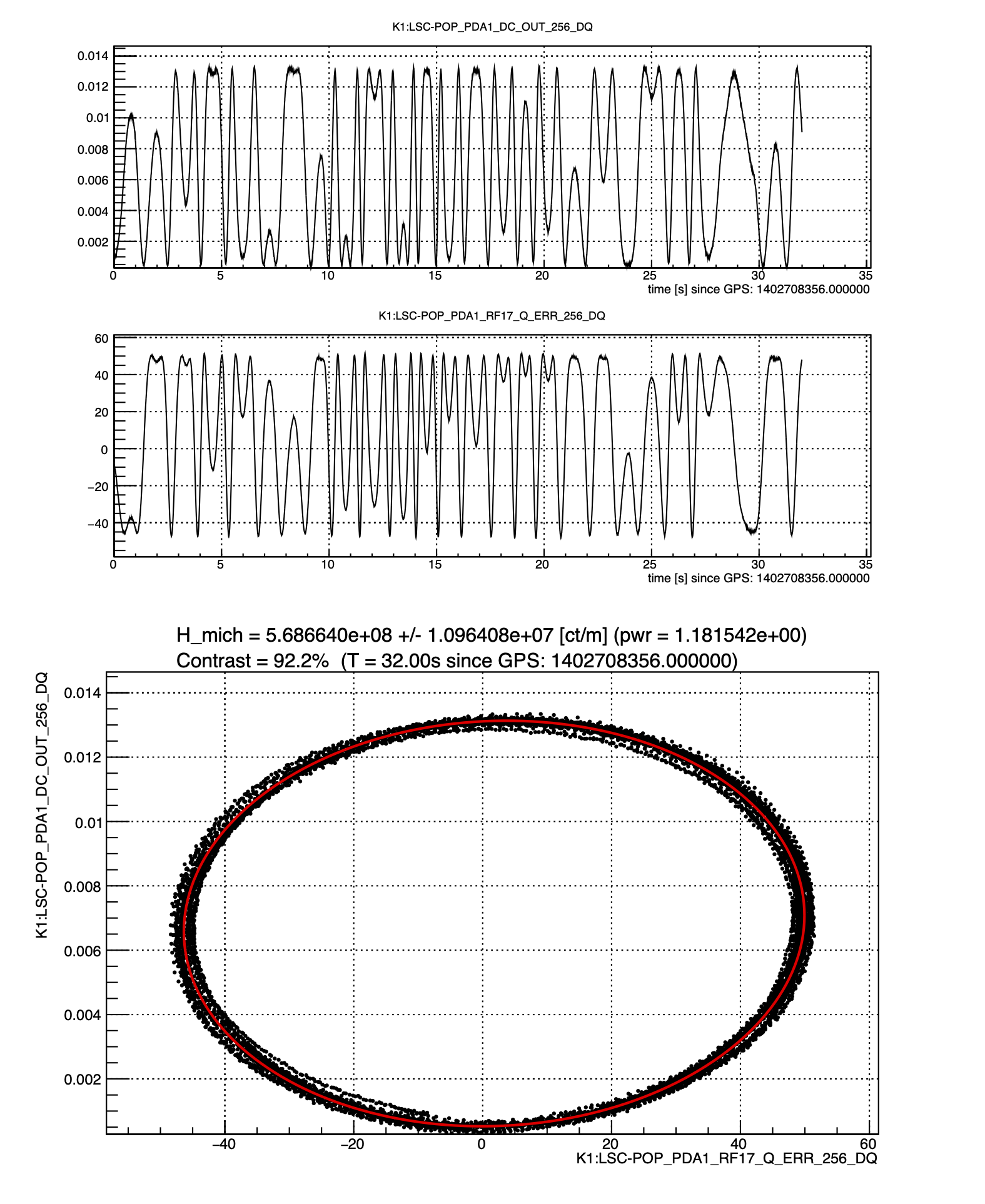
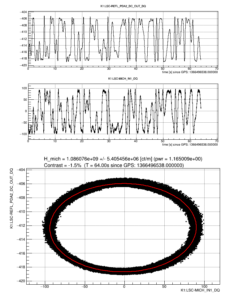
  • After that, we aligned ITMX with the guardian, then we tweaked the BS alignment to increase the fringe amplitude. Fig. 1 is the fitting result of free-swinging. The current MICH contrast is 82%. We stopped here today.
  • We requested the VERTEX guardian to go to "MICH_3F_LOCKED" in that state. However, the VERTEX guardian stopped at "LOCK_PREP" because the RMS of BS PIT motion (0.025) was slightly larger than the threshold (0.02). Ushiba-san said that the turbo-pomp is working now and it may shake BS at high frequency. So we decided to increase the threshold value to 0.05 for the MICH trial. After that, the VERTEX guardian locked MICH with a 3f signal.
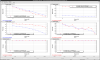
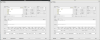
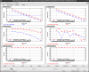
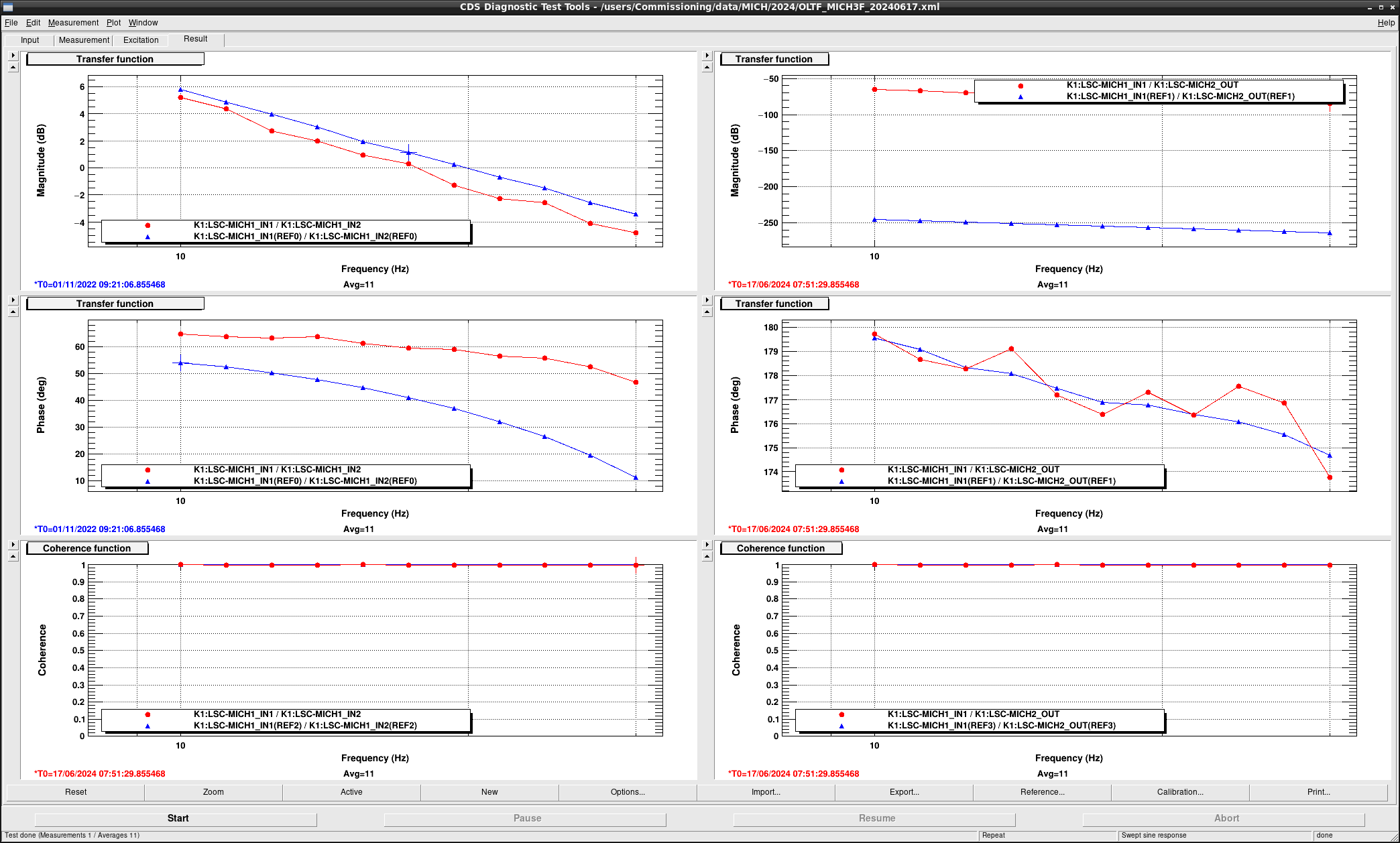
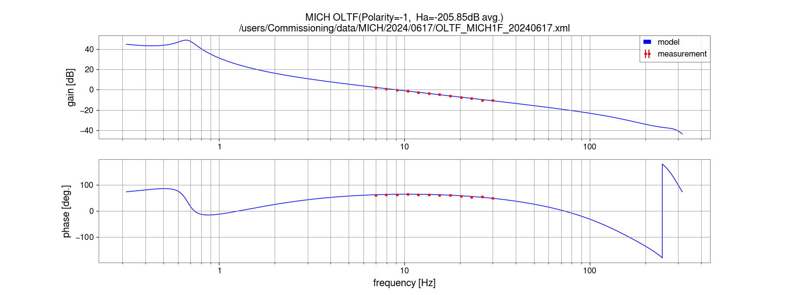
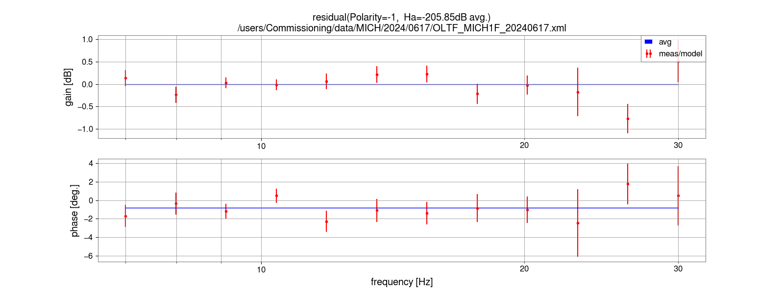
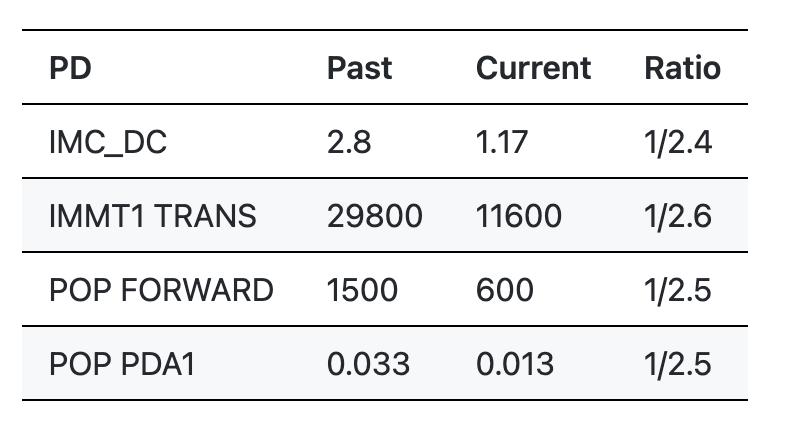
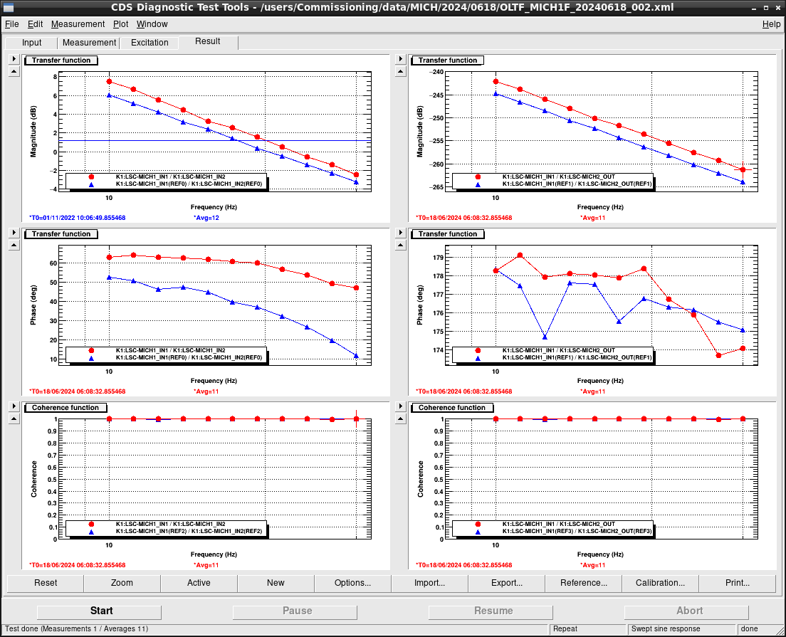
  • We measured the open loop TF of 3f MICH. Fig. 2 shows the result. The gain of the TF seems to be 1 dB lower than the previous one. This is because the current contrast (~80%) is 10% lower than the previous one (~90%). The phase differs from the previous one because the current roll-off frequency increased from 100 Hz to 300 Hz. So 3f MICH seems to be reasonable.
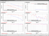
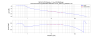
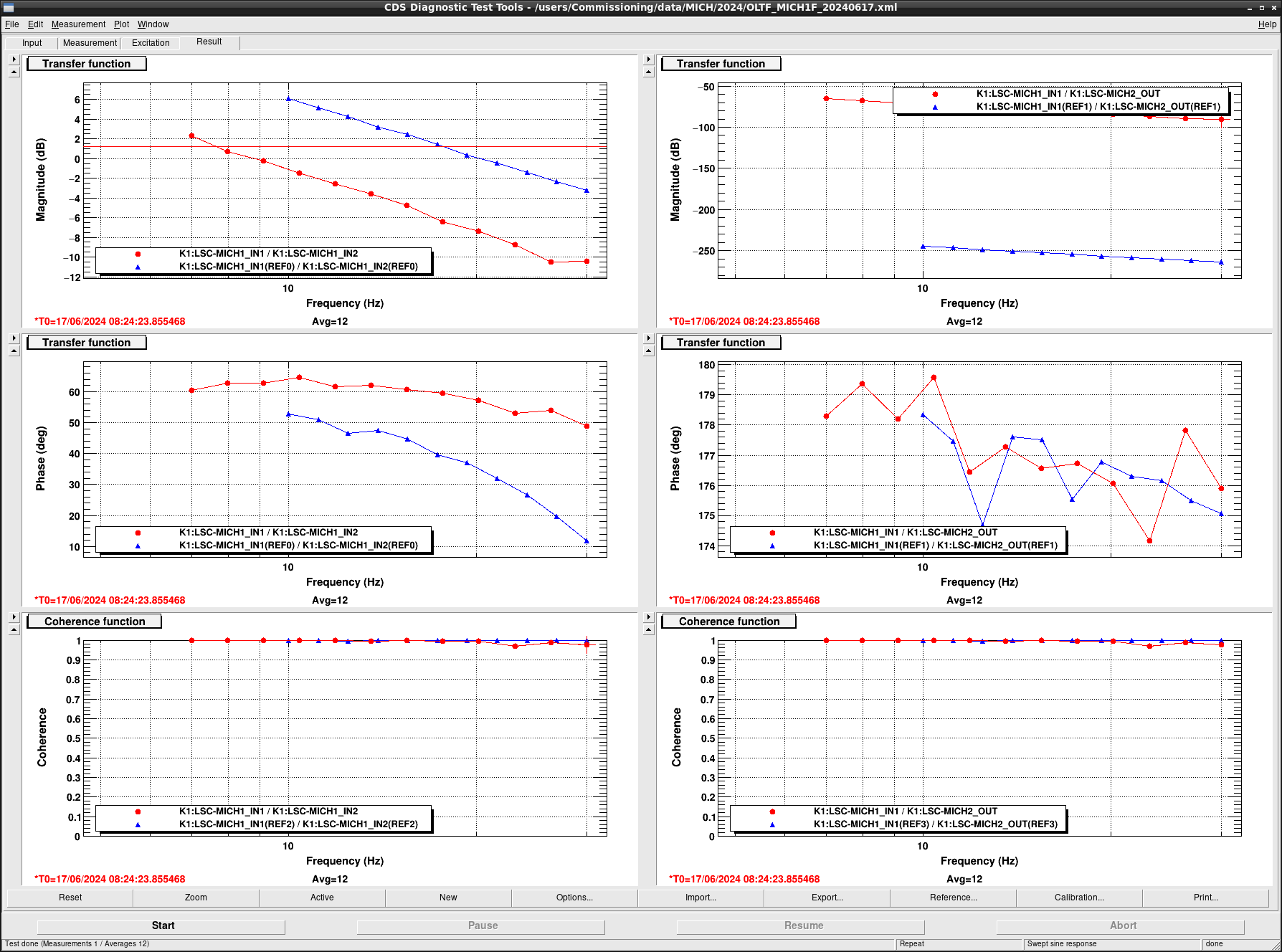
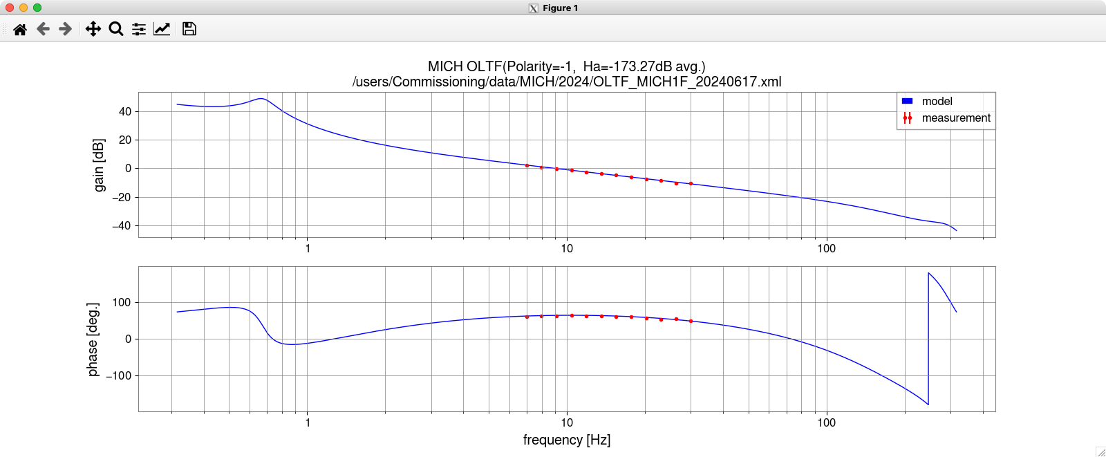
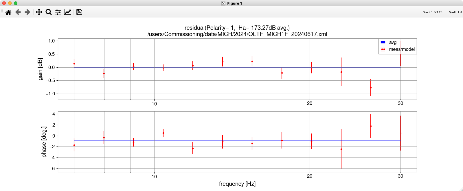
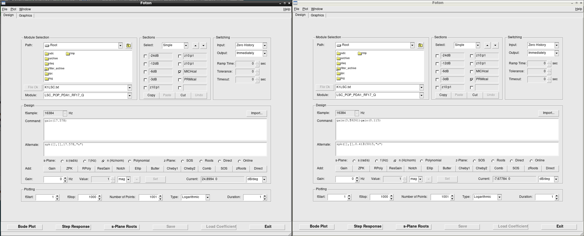
  • Second, we requested the VERTEX guardian to go to "MICH_LOCKED" and the VERTEX guardian succeeded in transitting and locking MICH with a 1f signal. We measured the open loop TF of 1f MICH. Fig. 3 shows the result. The phase is different from the previous one for the same reason as the 3f MICH case. On the other hand, the gain of the TF seems to be 8 dB lower than the previous one. For now, we are not sure of the reason. One possibility is that ITMY is not the best alignment so the beam was clipped somewhere up to POP RFPD. Anyway, tomorrow, ITMY alignment will be performed with GRY flash. After that, we will try the MICH lock again.
Images attached to this report
Comments to this report:
takahiro.yamamoto - 2:03 Tuesday 18 June 2024 (29950) Print this report

Abstract

I tried to calibrate MICH1F with today's data.
Estimated actuator efficiency is ~30 times larger than one in O4a.
I haven't found the cause of this difference yet. This issue will be a drawn-out struggle.
 

Details

At first, I compared raw measurement results of Michelson fringes in klog#29949 (today) and klog#24969 (before O4a). Today's optical gain is ~100 times (= ~40dB) smaller than one before O4a. On the other hand, OLTFs in today is only ~7-8dB smaller than one before O4a (Fig.1 in klog#24980). I think MICH servo filters haven't changed for a long time. If so, remaining 32dB (= 40dB-8dB) should come from actuator efficiency. Really...?

In order to investigate what happen, I applied OLTF fittings by using today's optical gain measurement. Results are shown in Fig.1 and Fig.2, and fitting is seemingly going well (no large difference between model and measurements). But estimated actuator efficiency is -173dB = 2.17e-9 m/ct which is ~40 times (= ~33dB) larger than previous estimation by using Michelson fringes as 5.238e-11 m/ct (see also "23/04/26 FSM" in the table of klog#25024). According to the log of fitting script, all analog, digital filters seems to be properly taken in to account. All components must be checked one-by-one tomorrow.

*** Log ***
### Measurement
File: /users/Commissioning/data/MICH/2024/OLTF_MICH1F_20240617.xml
GPS: 1402647881.8554688

### Sensing function
LSC-PD_DOF_MTRX_3_10: 1.0 (POP17Q -> MICH)
light(tdelay): 1e-07
IPC(tdelay): 6.103515625e-05
ADC(tdelay): 6e-07
dAA(RCG): (0.054285975, [(-1.3890221, 0.56547295, -1.43079926, 1.02500927), (-1.52191125, 0.90075507, -3.83663314e-06, 1.07232307)])
LSC-POP_PDA1_RF17_I: (0.9924460053443909, ['FM1', 'FM5', 'FM8'] => [])
POP17I(UWF): {'gain': 1.0, 'dB': 0.0, 'tau': 0.0, 'zero': [], 'fQ_z': [], 'pole': [14210.0, 18950.0], 'fQ_p': []}
POP17I(aAA): {'gain': 1.0, 'dB': 0.0, 'tau': 0.0, 'zero': [], 'fQ_z': [(66310.0, 1.042e+16)], 'pole': [7804.0, 50070.0, 373200.0], 'fQ_p': [(10600.0, 1.065)]}
LSC-POP_PDA1_RF17_Q: (1.0, ['FM1', 'FM5', 'FM8'] => [])
POP17Q(UWF): {'gain': 1.0, 'dB': 0.0, 'tau': 0.0, 'zero': [], 'fQ_z': [], 'pole': [14210.0, 18950.0], 'fQ_p': []}
POP17Q(aAA): {'gain': 1.0, 'dB': 0.0, 'tau': 0.0, 'zero': [], 'fQ_z': [(66310.0, 1.042e+16)], 'pole': [7804.0, 50070.0, 373200.0], 'fQ_p': [(10600.0, 1.065)]}

### Digital servo
LSC-MICH1: (1.0, [])
LSC-MICH2: (-1.0, ['FM5', 'FM6', 'FM8', 'FM9'])

### Actuation function
LSC-OUTPUT_MTRX_7_1: 1.0
VIS-BS_TM_ISCINF_L: (1.0, [])
VIS-BS_TM_LOCK_L: (1.0, [])
VIS-BS_TM_DRIVEALIGN_L2L: (1.0, [])
VIS-BS_TM_SUMOUT_L: (1.0, [])
CAL-CS_SUM_MICH_BS_TM: (1.0, ['FM9', 'FM5'] => ['FM9'])
VIS-BS_TM_LOCK_OUTSW_L: 1
VIS-BS_TM_ACTALIGN_1_1: 1.0085339546203613
IPC(tdelay): 6.103515625e-05
IOP(tdelay): 6.103515625e-05
DAC(tdelay): 7.62939453125e-05
dAI(RCG): (0.054285975, [(-1.3890221, 0.56547295, -1.43079926, 1.02500927), (-1.52191125, 0.90075507, -3.83663314e-06, 1.07232307)])
VIS-BS_TM_COILOUTF_H1: (1.0, ['FM1', 'FM2', 'FM3', 'FM6', 'FM7', 'FM8'] => [])
VIS-BS_TM_EUL2OSEM_1_1: -0.25
H1(aAI): {'gain': 1.0, 'dB': 0.0, 'tau': 0.0, 'zero': [], 'fQ_z': [(66310.0, 1.042e+16)], 'pole': [7804.0, 50070.0, 373200.0], 'fQ_p': [(10600.0, 1.065)]}
H1(DWF): {'gain': 1.0, 'dB': 0.0, 'tau': 9e-06, 'zero': [], 'fQ_z': [], 'pole': [], 'fQ_p': []}
VIS-BS_TM_COILOUTF_H2: (-1.0, ['FM1', 'FM2', 'FM3', 'FM6', 'FM7', 'FM8'] => [])
VIS-BS_TM_EUL2OSEM_2_1: -0.25
H2(aAI): {'gain': 1.0, 'dB': 0.0, 'tau': 0.0, 'zero': [], 'fQ_z': [(66310.0, 1.042e+16)], 'pole': [7804.0, 50070.0, 373200.0], 'fQ_p': [(10600.0, 1.065)]}
H2(DWF): {'gain': 1.0, 'dB': 0.0, 'tau': 9e-06, 'zero': [], 'fQ_z': [], 'pole': [], 'fQ_p': []}
VIS-BS_TM_COILOUTF_H3: (1.0, ['FM1', 'FM2', 'FM3', 'FM6', 'FM7', 'FM8'] => [])
VIS-BS_TM_EUL2OSEM_3_1: -0.25
H3(aAI): {'gain': 1.0, 'dB': 0.0, 'tau': 0.0, 'zero': [], 'fQ_z': [(66310.0, 1.042e+16)], 'pole': [7804.0, 50070.0, 373200.0], 'fQ_p': [(10600.0, 1.065)]}
H3(DWF): {'gain': 1.0, 'dB': 0.0, 'tau': 9e-06, 'zero': [], 'fQ_z': [], 'pole': [], 'fQ_p': []}
VIS-BS_TM_COILOUTF_H4: (-1.0, ['FM1', 'FM2', 'FM3', 'FM6', 'FM7', 'FM8'] => [])
VIS-BS_TM_EUL2OSEM_4_1: -0.25
H4(aAI): {'gain': 1.0, 'dB': 0.0, 'tau': 0.0, 'zero': [], 'fQ_z': [(66310.0, 1.042e+16)], 'pole': [7804.0, 50070.0, 373200.0], 'fQ_p': [(10600.0, 1.065)]}
H4(DWF): {'gain': 1.0, 'dB': 0.0, 'tau': 9e-06, 'zero': [], 'fQ_z': [], 'pole': [], 'fQ_p': []}
VIS-BS_TM_ISCINF_L: (1.0, [])
VIS-BS_IM_LOCK_L: (0.0, [])
VIS-BS_IM_DRIVEALIGN_L2L: (1.0, [])
VIS-BS_IM_SUMOUT_L: (1.0, [])
CAL-CS_SUM_MICH_BS_IM: (1.0, [])
VIS-BS_IM_LOCK_OUTSW_L: 0
VIS-BS_IM_ACTALIGN_1_1: 1.0
IPC(tdelay): 6.103515625e-05
IOP(tdelay): 6.103515625e-05
DAC(tdelay): 7.62939453125e-05
dAI(RCG): (0.054285975, [(-1.3890221, 0.56547295, -1.43079926, 1.02500927), (-1.52191125, 0.90075507, -3.83663314e-06, 1.07232307)])
VIS-BS_IM_COILOUTF_H1: (-1.0, ['FM3', 'FM6', 'FM7', 'FM8'] => [])
VIS-BS_IM_EUL2OSEM_4_1: -1.0
H1(aAI): {'gain': 1.0, 'dB': 0.0, 'tau': 0.0, 'zero': [], 'fQ_z': [(66310.0, 1.042e+16)], 'pole': [7804.0, 50070.0, 373200.0], 'fQ_p': [(10600.0, 1.065)]}
H1(DWF): {'gain': 1.0, 'dB': 0.0, 'tau': 9e-06, 'zero': [], 'fQ_z': [], 'pole': [], 'fQ_p': []}

Images attached to this comment
kenta.tanaka - 9:42 Tuesday 18 June 2024 (29955) Print this report

Just a memo

I turned off FM{2, 4, 6, 9} in the LSC-DGCARM filter for this trial. Fig. 1 is the state before this trial as a reference.

Images attached to this comment
takahiro.yamamoto - 15:38 Tuesday 18 June 2024 (29958) Print this report

[Kenta, YamaT]
 

Abstract

Finally, we found that optical gain estimation by Michelson fringes was not done in proper configuration and corrected actuator efficiency is consistent with O4a value within ~3%.
Although not directly related to inconsistency in this time, I found cause of the inconsistency between FSM and Pcal in O4a comes from the handling of the laser norm scale.
As for the latter issue, I'm waiting for a cross-check by someone.
 

Details

When MICH is locked by guardian, guardian engages FM1 (for compensating whitening gain), FM5 (for compensating whitening filter) and FM8 (for gain of MICH lock). During an OLTF measurement, these filters were surely engaged as shown in Fig.1. On the other hand, FM1, FM5 and FM9 (for gain of PRMI lock) were engaged during a Michelson fringe measurement as shown in Fig.2. So these two measurements were done in different configurations.

Checking FM8 (MICH gain) and FM9 (PRMI gain) by the foton file, MICH and PRMI gain is 17.578 and 0.41315015, respectively (see also Fig.3). So in order to estimate actuator efficiency, difference in these two gains must be taken into account and it can be done easily and accurately because this is just a digital gain. Though Michelson fringes were measured with PRMI gain (= 0.41315015), correct gain was MICH gain (=17.578). So RFPD signal should be corrected by a factor of ~42.546 (= 17.578 / 0.41315015). In other words, estimated optical gain should be also corrected by a factor of 42.546 as follows (see also Fig.4 and Fig.5).
Correct: 4.986e+8 +/- 9.3e+6
Incorrect: 1.172e+7 +/- 2.2e+5
As discussed below, this corrected value also contains a mistake as ~10-20%.

OLTF measurement was done in proper configuration. So we don't need to apply any correction for OLTF measurements. I did OLTF fitting again with corrected optical gain, then actuator efficiency was estimated as 5.10e-11 +/-1.0e-12 which was consistent with ~3% in the previous measurement ("23/04/26 FSM" in the table of klog#25024).


By the way, I checked bugs in my scripts in order to investigate inconsistency in the estimated actuator efficiency between this time and O4a and found that this ellipse fitting code compute the "optical gain" from displacement to K1:LSC-POP_PDA1_RF17_Q_ERR_DQ not to K1:LSC-MICH_IN1. On the other hand, actuator efficiency estimation treated "optical gain" as from displacement to K1:LSC-MICH_IN1. This mistake doesn't affect to the comparison between the estimated values in this time and past because both this time and past are affected as same level (fortunately short Michelson measurements are always done with 1.1-1.2W output from IMC.). On the other hand, this fact affected to the comparison between the calibration by pcal and Michelson fringes as a factor of 1.1-1.2.

In fact, laser power during the measurement in klog#24969 is ~1.16. So optical gain and actuator efficiency should be corrected as a factor of 1/1.16 and 1.16, respectively. Finally estimated actuator efficiencies by FSM on '23/4/26 must be corrected as 5.238e-11 +/- 0.074e-11 to 6.076e-11 +/- 0.086e-11. Almost all inconsistency on the comparison between Pcal and FSM in klog#24969 can be explained. I want to wait cross check by someone to conclude this issue.

Note that: Fortunately (again), DARM, PRCL, and MICH calibrated signals were provided based on the pcal calibration, so these signals in O4a were not also affected.

Images attached to this comment
dan.chen - 17:09 Tuesday 18 June 2024 (29964) Print this report

With Yuzurihara, Tanaka, Yokozawa, YamaT, Ushiba

Summary

The BS alignment was adjusted following the ITMY alignment, with final P and Y values of (40.7, -17.4) and a measured contrast of 92.2%.
A 6dB gain difference was investigated, initially suspecting laser power loss and clipping, but measurements showed no clipping and significant reductions in laser power across multiple sensors.
The actual issue was incorrect phase adjustment on POP_PDA1_RF17. Correcting the phase adjustment resulted in only a minor gain difference of 0.8 dB.

Details

  1. Because ITMY alignment was adjusted in this morning as reported on [klog29952](https://klog.icrr.u-tokyo.ac.jp/osl/?r=29952), we adjusted the alignment of BS.

    1. `K1:VIS-BS_TM_SET_P_OFFSET` and `K1:VIS-BS_TM_SET_P_OFFSET` were adjusted by moniting POP PDA1 `K1-LSC-POP_PDA1_DC_OUT_DQ`.

    2. The final P and Y values: (40.7, -17.4)

    3. Measured the contrast: 92.2% (fig1)

  2. Investigation of 6dB difference in gain from the previous measurement (Measured at 01/11/2022 10:06:50)

    1. Lock conditions

      1. VERTEX: MICH_LOCKED state

      2. VIS_ITMY: ALIGNED (This is to prevent oscillation of ITMY)

      3. Filters in K1LSC-MICH2: ELP300=ON, OBS=OFF

    2. Suspect loss of laser power

      1. Check the laser power (fig2)

      2. Clipping survey

        1. Changed state: VERTEX=DOWN, ITMX=LOCK_ACQUISITION, ITMY=MISALINED

        2. We changed P,Y in IMMT1 (`K1:VIS-IMMT1_TM_TEST_P_OFFSET` and `K1:VIS-IMMT1_TM_TEST_Y_OFFSET`) and looked at POP PDA1 and REFL PDA1 to see if the signal was reduced.

        3. Result

          • TEST_P_OFFSET = 0 -> REFL_PDA1 = 0.08

          • TEST_P_OFFSET = +18000 -> REFL_PDA1 = 0.076

          • TEST_P_OFFSET = -18000 -> REFL_PDA1 = 0.04

          • TEST_Y_OFFSET = 0 -> REFL_PDA1 = 0.08

          • TEST_Y_OFFSET = 3000 -> REFL_PDA1 = 0.074

          • TEST_Y_OFFSET = -3000 -> REFL_PDA1 = 0.058

          • (POP_PDA1 did not change at any case.)

        4. We also performed the same task as IMMT1.

        5. From thses results, we belive the beams are not clipping.

    3. We checked phasing of POP_PDA1_RF17 as reported on [klog29961](https://klog.icrr.u-tokyo.ac.jp/osl/?r=29961)

      1. As reported on the klog, we used MICH to adjusted the phase, which makes produced different results.

      2. After the phase adjustment, we locked MICH with VERTEX guardian like what we did above.

  3. OLTF measurement again

    1. Meausred result is the following. (fig3)

    2. Note

      • This measured result(red on the graph)

      • As for GAIN, the present results (red) were only 0.8 dB larger, but they were almost identical. Accuracy of phasing made this diff?

      • Phase are different from the old measurement because the frequency of ELP is defferent (old=100Hz, current=300Hz)

      • In order to have a good comparizon, we applied 1.14e-9 to the current measurement, which containns the unit different of MICH1_IN1 and the gain different of MICHcal in POP_PDA1_RF17 filter banks.

Images attached to this comment
kenta.tanaka - 9:25 Wednesday 19 June 2024 (29977) Print this report

For this trial, I temporally modified the "LOCK_PREP" state in the VERTEX guardian to request ITMY to go to not ""LOCK_ACQUISITION" but "ALIGNED" because ITMY start to oscillate in the current LOCK_ACQUISITION state.

After the modification of the ITMY LOCK_ACQUISITION state, we need to restore the guardian to the original one.

Shingo Hido - 15:15 Wednesday 19 June 2024 (29992) Print this report

Hido

Abstract
I performed a cross-check on the above point.
According to my calculations the effect of the laser power is (1.1651 +- 0.0082) which is consistent with the actual measurement, ~1.16.
 
1.1651 +- 0.0082 =  (1.2655e9 + -6.2990e6) / (1.0861e9 +- 5.4055e6)

Details:
I confirmed the effect by taking the ratio of A, 1.2655e9 + -6.2990e6, in FIg.1 to B, 1.0861e9 +- 5.4055e6, in Fig.2.
A: optical gain that calculated from "K1:LSC-REFL_PDA2_DC_OUT_DQ" to "K1:LSC-REFL_PDA2_RF51_Q_ERR_DQ"
B: optical gain that calculated from "K1:LSC-REFL_PDA2_DC_OUT_DQ" to "K1:LSC-MICH_IN1_DQ"

Since the RF17 signal was not input to K1:LSC-MICH1 at the measurement time, the RF51 signal was used.
The effect of the laser power, whether RF51 or RF17, works the same way and therefore does not affect this cross-check.

Images attached to this comment
Search Help
×

Warning

×