Reports 1-1 of 1 Clear search Modify search
MIF (General)
tomotada.akutsu - 6:12 Friday 24 May 2024 (29629) Print this report
Optical beam alignment from BS to SRM

Ushiba, Hirata, D. Chen, Akutsu; following 29541, 29519; On May 23, 2024

Summary

Algined the optical beam to SRM center, and roughly checked whether suprious ghost beams or scattered light might exist or not, and not that.

Details

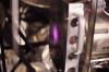
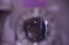
It turned out that when the work 29541 and 29519 was done, the GV between IYA and the Y arm did not open, so today firstly it was opened by Uchiyama-san. Then, once repeated the alignment work described in those previous klogs to bring the IR beam to SR3. With this condition, we firstly checked the SR3 beam spot, and it seemed not so changed from the one reported in the previous klogs. (See Fig. 1; for some reason only a lower resolution photo can be uploaded today...) So we left it, although there is still a mystery for the current position of the beam spot on SR3 as already reported in the previous klogs; this beam spot should be automatically determined with the arms, so we could not do anything. We roughly checked the relevnt mid baffle won't clip much the main beam.

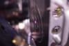
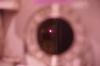
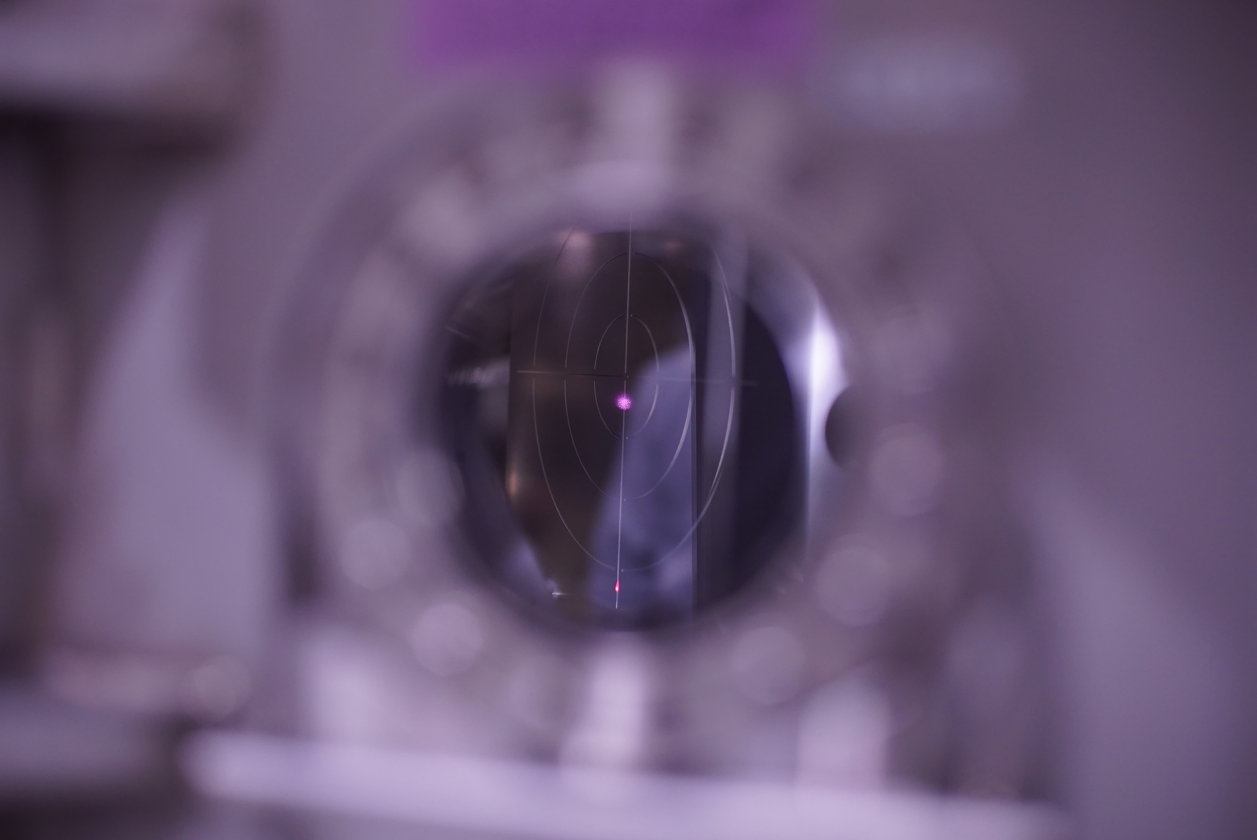
Next, we checked the IR beam spot at SR2 (Fig. 2); when SR3 at ALIGNED state, the IR beam spot on SR2 (precisely speaking, on the SR2 target) was already centered. So we left it. It seemed the mid baffle aperture did not clip the IR beam. We also check if there might be suprious stray light field, and not such ones. Anyway, in simulation, many ghost beam would be brought around here (see JGW-E1910040).

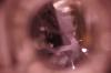
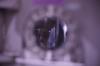
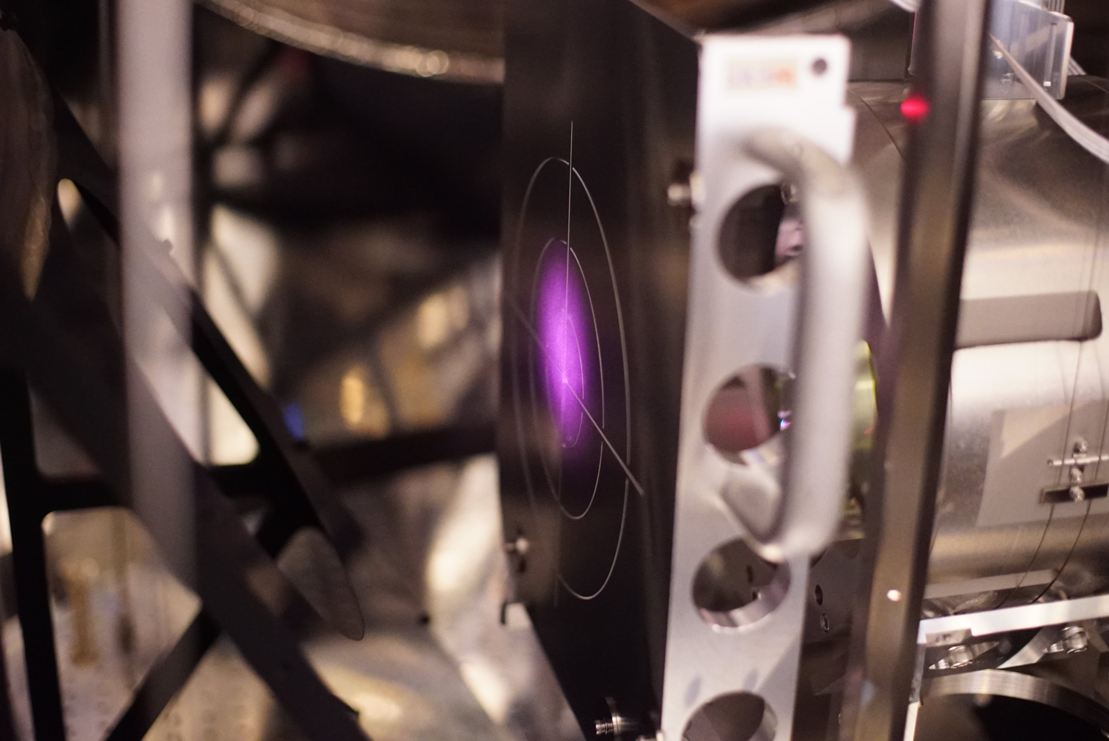
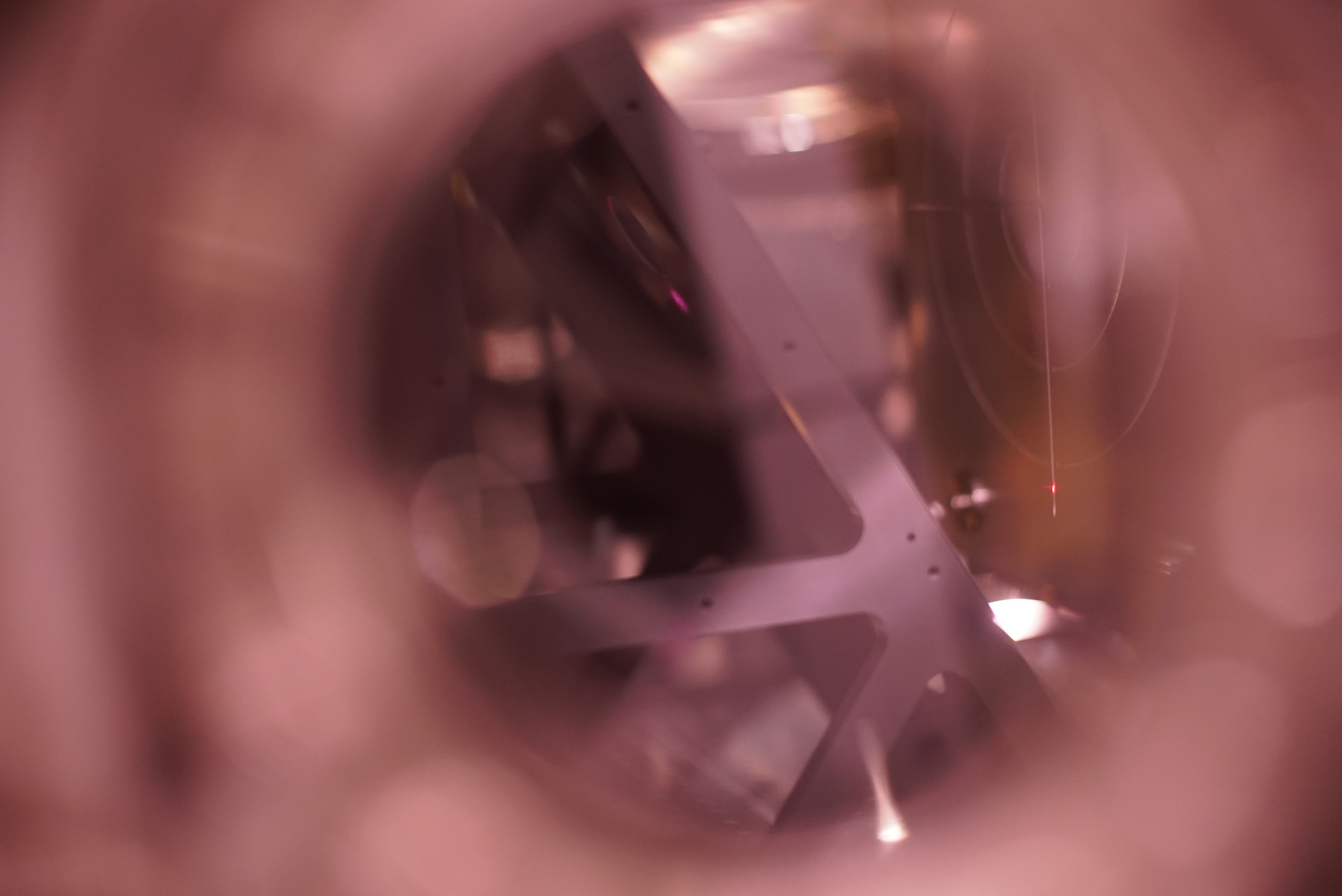
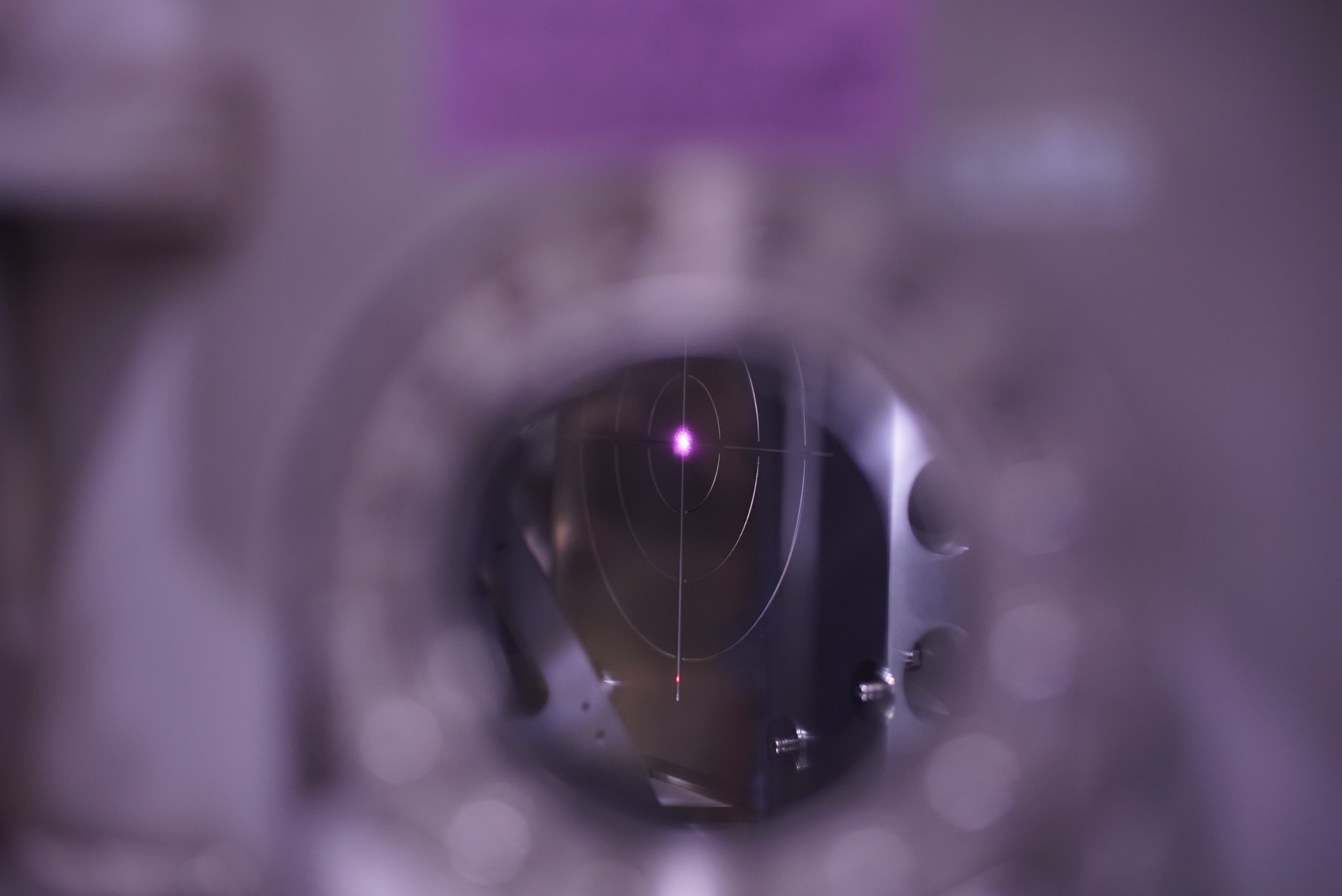
Then, we set the SRM target at SRM, and found that the IR beam spot brought at SRM was too off in pitch down, and so hitting at SRM HR mid baffle (Fig. 3). Accoding to Ushiba-kun, this might be not so strange when considering the what were done for the alignment of the upstream optics. Anyway, we tweaked SR2 alignment to bring the IR beam spot to the center of the SRM target (on the way: Fig. 4, completed: Fig. 5 and 6). While doing so, the SR2 oplev went out of range, and we took time to do centering the oplev, and checked the SR2 Guardian working with the re-centered oplev setup. The detail might be reported later by others.

Then we tried to find ghost beams from SRM; although this "dummy" SRM's both surfaces are AR coated (where is the SRM specification...?), there might be relevant ghost beams. But we could not find them except for one today. We will check again tomorrow. Anyway, during O4a commissioning, the SRM suspension was intensionally shaken but no sensitivity worsen found (which klog?), according to Ushiba-kun. I am not sure what will happen for the more improved sensitivity...

Notes

  • As usual, before opening each chamber's side hatch, you should confirm the relevant each suspension would be at PAY_FLOAT state; check if the PAY_FLOAT could keep the suspended mirror's alignment at the same or similar with that of ALIGNED state.
  • Only for SR3, for some reason (maybe due to the area blew off by wind flow from the KOACH filter would be large...?), BS (not SR3... strange) suspension would be shaken much , so you need to take care of the BS suspension somehow.
  • The SR3's target center had been set up so that this center point would come on the line connecting the center lines on the recoil masses at SR2 and SR3. These center lines had been illuminated by a laser level, and the SR3 target plate center with respect to the target body/handle had been adjusted. So do SR2. So the IR beam from BS might not hit the SR3 target center. The IR beam from SR3 to SR2 should hit the center of the SR2 target. What is strange/mysterious is that the IR beam spot on the SR3 target should come slightly in minus X direction in design, while the real wolrd shows it comes slighlty plus X direction...
Images attached to this report
Comments to this report:
dan.chen - 6:51 Friday 24 May 2024 (29630) Print this report

Date: 2024/5/24

Ushiba, Hirata, Akutsu, D. Chen

Contains duplicate content with klog-29629.

Summary

We aligned the IR beam referenced with Yarm up to the SRM surface. At this time, SR2 alignment adjustments were performed and oplev centering was also performed.
We searched for the reflected light from the SRM, and although we found one that seemed to be it, we haven't been able to find the other one.

Details

  1. As the GViya was opened, we checked the beam alignment again and aligned it up to the surface of SRM.

    1. Aligned the IR beam inputting into the SR area with the Yarm as the reference.

    2. Checked the beam position at SR3 with the target -> it is almost at the center of the target. (Fig 1 on klog-29629)

    3. Checked the beam position at SR2 with the target -> it is at the center of the target. (Fig 2 on klog-29629)

    4. Checked the beam position at SRM with the target -> the beam was about 25mm below the center of the target. (Fig 4 on klog-29629)

    5. Adjust the beam position at SRM by changing the alignment of SR2 -> the beam was adjusted to the center of the target of SRM. (Fig 5 on klog-29629)

      • To do this, the direction of SR2 had to be moved so far beyond the oplev range at this time.

      • Especially the beam position of the tilt oplev went out of the upper side range of the QPD.

    6. With the beam centered on the SRM target, the SR2 oplev (tilt and length) was adjusted to the center of each QPD by changing the QPD positions.

      • We did not touch the length direction of the length oplev QPD.

      • At the time, we confirmed that the oplev beam coming out of the SR2 vacuum chamber was not clipped by the first mirror. = We looked at the first mirror and made sure the edges were not shining with the oplev beam. (Forgot to take a picture.)

      • Closed the windshield of SR2 oplev.

    7. We closed the loop using SR2 peoplev and checked the beam position at SRM -> the beam still was at the center of the SRM target. (Fig 6 on klog-29629)

  2. SRM reflected beam searching

    1. SRM state was kept at SAFE.

    2. We tried to find the reflected light by SRM. There should be two, one from the front surface (+y side) of the SRM and the other from the back surface (-y side) with the edge.

    3. We found one faint beam between SRM and the its front (+y side) mid-size baffle. This beam was shifted about 20 mm from the main beam at a position about 20-30 cm away(+x side) from SRM. Because we could not find other faint beam around, this one might be the beam reflected by the back surface of SRM. This faint beam hits the mid-size baffle of SRM. Once the main beam was blocked, this beam disappeared, suggesting that it originated downstream from the SRM surface. Since no other beams were observed in this region, this beam might be the beam reflected by the backside of the SRM.

    4. We looked for the assumed beam being reflected from the front surface of the SRM.

      1. Looked for it in the SRM chamber but could not find it.

      2. Looked for it in the SR2 chamber but could not find it.

      3. Looked for it in the SR2 chamber while swinging the SRM in the tilt direction, but could not find it. The vertical movement of the reflected beam on SR2 was assumed to be a few mm.

    5. As a result, we found one beam that we think was reflected by the SRM back surface(?), but not the other.

takafumi.ushiba - 7:38 Friday 24 May 2024 (29632) Print this report

Suspension related topics during the alignment work:

1. XARM was aligned with the current usual procedure (klog29346).
2. SR3 was aligned so that GRY beam hit on the ETMY center by using Tcam.
3. Place PD at EYA chamber so that GRY beam hit on the center of PD.
4. Align BS to hit the IR beam on the center of the PD.

Since GV between IYA and Y arm was opened, alignment of SR3 and BS were changed several tens of urad in the same direction but as reported in the original log, no significant change can be observed on SR3 and SR2 beam spot.

To center the beam spot on SRM target, SR2 was moved along minus pitch direction by about -1500 cnts at IM OPTICALIGN OFFSET with OLDAMP_OFF state (since OpLev became out of range during the work, we could not use OpLev setpoint for the alignment).
After that, Dan and Hirata-san performed centering of SR2 OpLev, so now SR2 good alignment can be reproduced at ALIGNED state.
During the SRM reflection beam investigation, I requested PAYFLOAT state for SRM and excite 0.84Hz pitch resonance from TM_TEST_P_EXC with several hundred cunts, which causes +/-200 urad oscillation of SRM.
Since the distance between SRM and SR2 is 15m, +/-200 urad shakes the beam by several mm at SR2, which should be visible if we found the SRM reflection at SR2 with sensor cards (unforetunately, we could not find the beam, though).

Note:

BS actuators are weak and sometimes BS control was saturate when SR3 side flange was opened (somehow SR2 and SRM side flanges didn't make BS saturated. Maybe air flow is different? SR3 COACH was placed in front of the opened flange while the others are slightly off from the flanges).
So, when SR3 side flange is opened, BS needs to be manually aligned at DAMPED state with IM_OPTICALIGN.
 

tomotada.akutsu - 10:13 Friday 24 May 2024 (29635) Print this report

According to Aso-san, the SRM specification is here JGW-G2415804, and the transparent SRM is of "ITEM 2", and the AR coat is < 500ppm (aiming at < 50ppm), very low reflectivity. Considering the power input to SRM (and the beam radious of several mm), it would be impossible to "see" these ghost beam spots anywhere.

Search Help
×

Warning

×