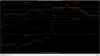
I changed IP1 PZT offset to align IMC.
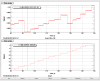
Figure 1 shows the WFS error signals, PZT offsets, and IM trans power.
After changing the offset to PZTs, IMC trans power increased and WFS error signals were decreased.
Though I tried to move IP1 till both PIT and YAW WFS signals are zeros but couldn't because IP1 YAW offsets hits its limit.
So, we need to enter PSL room and move IP1 manually if further alignment is necessary.
Demod phase adjustment and/or Ushiba san's manual alignment using IP1 PZT seems to have helped.
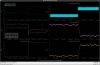
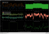
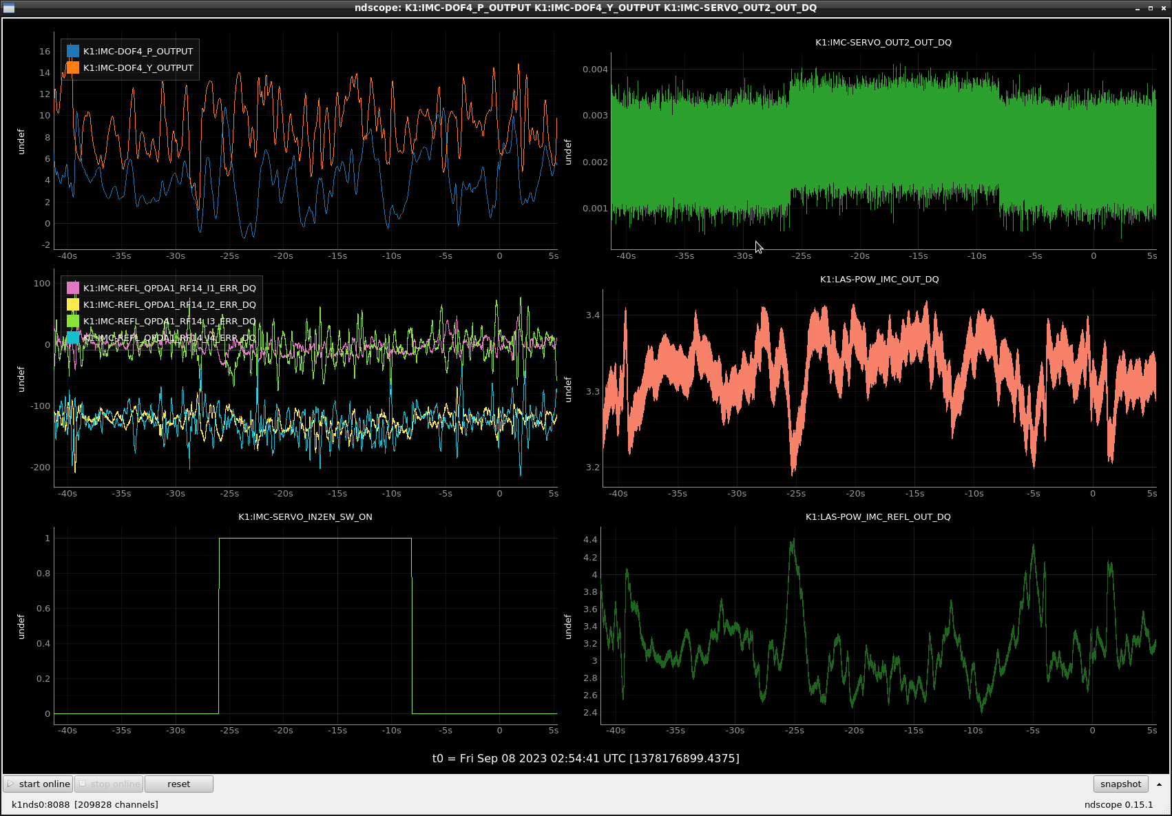
1st attachment shows the state of things before today's work. IMC servo IN2 is turned on (left bottom), IMC servo error point changed by 5mV or so (top right), and all quadrants of WFS moved in the same direction in I-phase (left middle), i.e. this is a length-like signal not alignment. However, quadrants are not perfectly balanced in RF. If you look at the quadrants closely, red (I1) and yellow(I3) were well balanced before the IN2 is turned on, but yellow got larger (more negative) than red after. Likewise, purple (I2) got more negative than green (I4) after. This resulted in non-zero YAW error, which was integrated until it hit the limiter (top left green). IMC transmission/reflection went down/up because of this. Also, with the ASC on, when we change K1:IMC-SERVO_OFS_COM_CALI_OFFSET by 5 or 6mV we see the exact same thing though I don't have a plot for that.
When we turned on the IN2 while IMC ASC was off, there was a small change in IMC transmission/reflection but not as large as this.
After adjusting the demod phase (2nd attachemnt), the change in the IMC servo error point is the same as before, but the kick to the WFS got much smaller. There's still length-like jump to WFS quadrants, but they're well balanced even after the kick and the impact to the ASC is much, much smaller.

Summary:
All IMC QPD1 quadrants jump by non-negligible amount when IN2 of the IMC board is enabled, even though they don't kick ASC as hard as it used to because the jumps are well balanced. I confirmed that this common jump in WFS quadrants is quantitatively consistent with the jump in the IMC length signal.
What was done:
For the length error point jump, I used OUT2 of IMC servo board (which is connected to IN1).
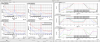
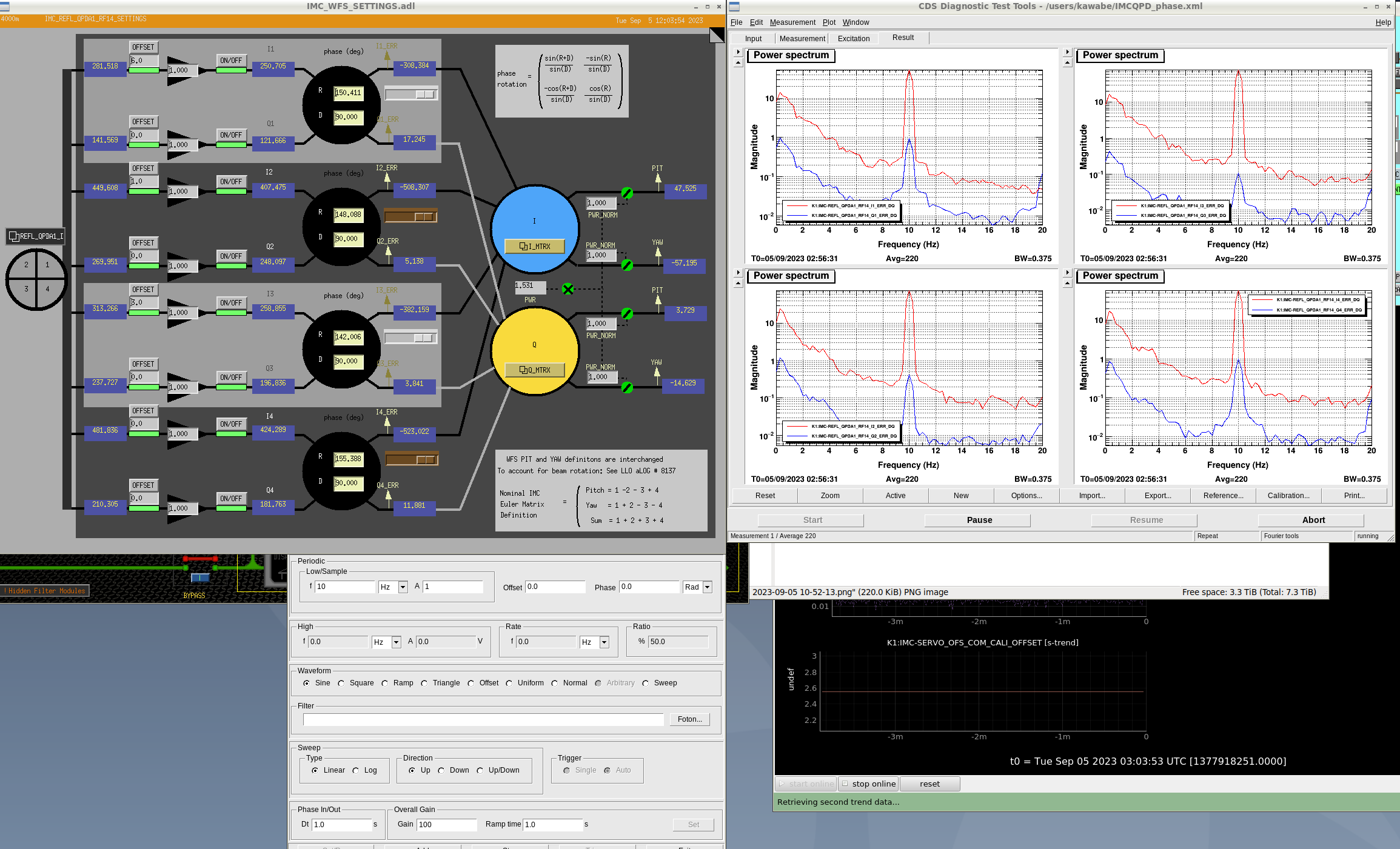
In the first attachment, left is the same plot as shown in the "after demod phase was adjusted" screenshot in https://klog.icrr.u-tokyo.ac.jp/osl/?r=26638, but the right plot shows the transfer function from OUT2 to each quadrant at the injection frequency of 10Hz. Everything is within 90+-2dB range and out of phase.
OTOH, if you look at the second attachment (which is the same thing as the 2nd attachment in the parent alog), OUT2 jumped by ~+5mV while all QPDA1 I error signals jumped in negative direction by ~160 counts or so, i.e. the DC jump ratio is -160/5e-3=-32000, i.e. 90dB and out of phase.
Summary:
Is 5mV jump in the IMC error point reasonable? The answer is it's not totally unreasonable though we have to be unlucky.
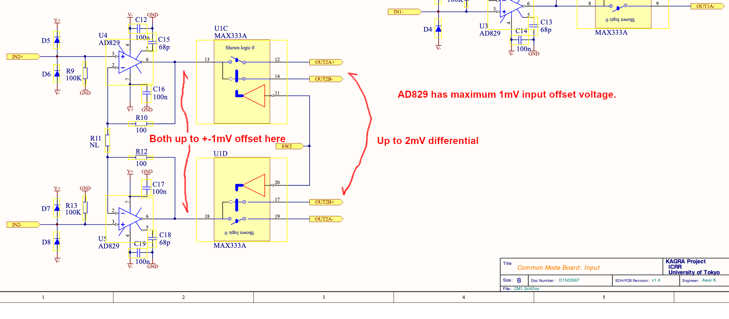
In the worst case (all AD829 opamps for the IN2 buffer, differential->single conversion and whitening stages have the maximum 1mV input offset voltage and they all add up in the same sign), the offset would be ~7.5mV for the IN2 gain of -10dB.
As such, the problem seems to be that the IMC error signal is too small before IN2 is added. If we can reduce the analog gain for the NPRO PZT drive path (e.g. by a factor of 2 or 4), reduce the FAST gain, increase the IN1 gain and e.g. increase the FAST gain of CARM board at the same time, it would be good (but you'll reduce the range of the PZT control, which may or may not impact the locking).
Another mitigation strategy, though not a great one, is to increase IN2 gain (K1:IMC-SERVO_IN2GAIN, -10dB as of now) and decrease CARM FAST gain (K1:LSC-CARM_SERVO_FASTGAIN, +5dB as of now) at the same time to keep the total gain for CARM->IMC path constant, and search for a combination that minimizes the offset. For example, if you set the K1:IMC-SERVO_IN2GAIN to -8dB, the worst case IN2 offset coming from the IMC board opamps themselves self would be 3.6mV, not 10mV.
Details:
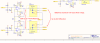
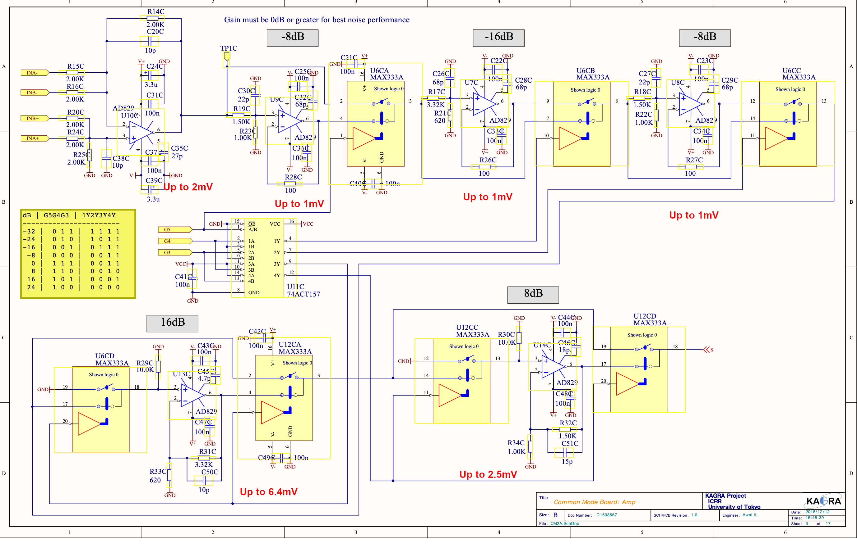
IMC servo board is https://gwdoc.icrr.u-tokyo.ac.jp/cgi-bin/private/DocDB/ShowDocument?docid=3567. I looked at the circuit diagram with Kamiizumi-san and Tomura-san.
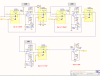
IN2 chain upstream of the IN2 summation point comprises the differential receiver (1st attachment), differential->single ended conversion (1st opamp on the 2nd attachment), whitening stages (2nd and 3rd attachment) and the buffer (last opamp of the 3rd attachment).
All opeamps are AD829 with 1mV or smaller input offset voltage. Diff receiver output offset is up to 2mV, diff->single adds another 2mV, these cannot be bypassed so they will produce up to 4mV of offset at the output of the diff->single converter. That will be amplified according to the whitening stages (i.e. if the whitening gain is -10dB, up to 4mV will become up to 4mV*10^(-10/20)=1.3mV in the output of the last opamp in the 3rd attachment).
Likewise, each whitening stage with negative dB (-16dB, -8dB) will produce up to 1mV in the output of the opamp, which will go through the gain stages downstream.
Each whitening stage with positive dB (16dB, 4dB, 2dB, 1dB) will produce up to 1mV times the gain of that stage in the output of the opamp (e.g. for 8dB stage, it will be 1mV*10^(16/20)=2.5mV), which will go through the gain stages downstream.
Final buffer in the chain will produce up to 1mV.
The offset will of course depend on the whitening gain (as well as the input offset voltage of opeamps involved). As such, you can change IN2 gain while monitoring OUT2 and see which gain will produce a better offset.
With -10dB gain, -16dB, 4dB and 2dB stage will be used. In this case the offset would be 4mV*10^(-10/20) + 1mV*10^(6/20) + 1mV*10^(6/20) + 1mV*10^(2/20) + 1mV ~ 7.5mV in the worst case.
With -16dB gain, it would be 4mV*10^(-16/20) + 1mV + 1mV ~ 2.6mV in the worst case. With -8dB gain it would be up to 3.6mV.
That there should be up to 1mV offset coming from the HPF output of the CARM FAST path into IN2 of IMC board, too, but that offset won't depend on CARM FAST gain.

To check the good offset value of IMC CMS IN2 gain to mitigate the unwanted offset of IMC servo, I changed the IN2 gain and found that OUT2 signals (offset in IMC error signals) changes even though IN2 switch is open (fig1).
The amount of change of the offset is about 8 mV, which is not negligile amount compared with the RMS of error signals.
There seems to be electrical couplings between IN1 and IN2 signals after each amplifier board.
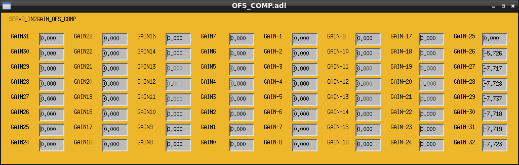
(Ushiba-san found that the strange IN2 leakage-like phenomenon he reported above was due to the SERVO_IN2GAIN_OFS_COMP that works even when IN2 input is off. I manually zero-ed all non-zero components of K1:IMC-SERVO_IN2GAIN (1st attachment GAIN-26 to GAIN-32) and OUT2 didn't respond to IN2 gain when IN2 was disabled.)
Summary:
I scanned the IN2 gain of the IMC board while the IMC was locked and measured the error point offset. Based on that, I set K1:IMC-SERVO_IN2GAIN to -16dB (6dB down from -10dB) to minimize the offset, and K1:LSC-CARM_SERVO_FASTGAIN to +11dB (6dB up from +5dB) to compensate.
After these changes I don't see any meaningful jump in IMC QPDA quadrants when enabling IN2.
In the future, we must change the frontend such that SERVO_IN2GAIN_OFS_COMP works only when IN2 input is turned ON. That way, we can use the feature to compensate for the electronics offset for all gains, we don't have to worry about this.
Details:
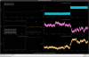
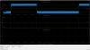
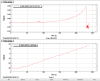
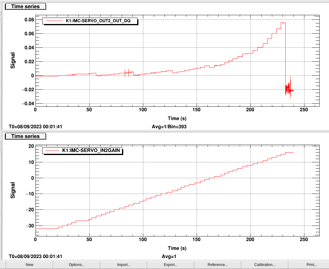
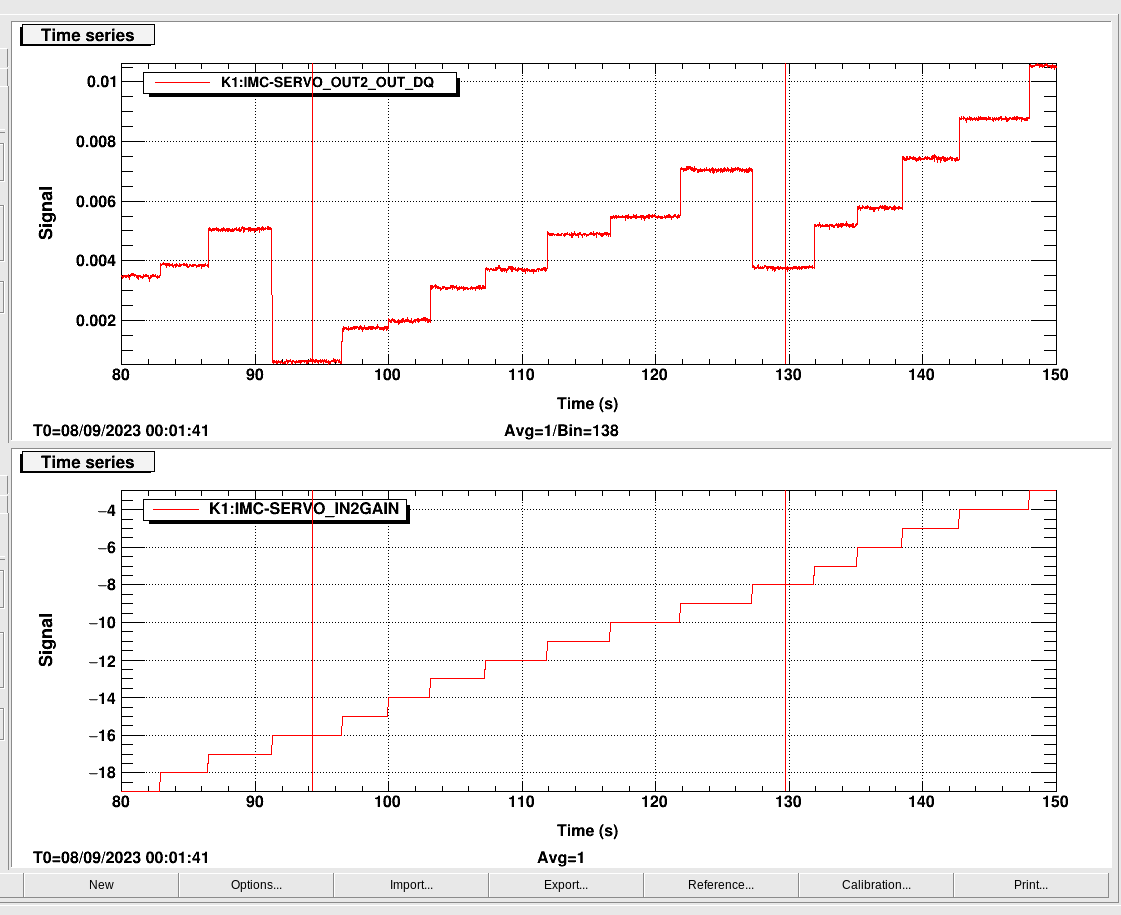
With offset compensation for IN2 disabled, I scanned the IN2 gain while the IMC was locked, and looked at OUT2 (2nd attachment). Just by looking at it, -16dB seems to be the sweet spot (3rd attachment, which is just a zoomed-in view of 2nd attachment). Note that I couldn't go more than 15dB as the offset becomes so big IMC would lose lock . Also note that IN1 gain (not IN2 gain) was 11dB during the scan.
Just to list a few numbers:
| IN2 state | IN2 gain (db) | OUT2 (mV) | Out2, IN2 enabled - IN2 disabled difference |
| disabled | 0.21 +-0.08 | NA | |
| enabled | -10 (current setting) | 5.5 +- 0.3 | 5.3 +- 0.3 |
| enabled | -8 | 3.8 +- 0.3 | 3.6 +- 0.3 |
| enabled | -16 | 0.61 +- 0.04 | 0.40 +- 0.09 |
For now, I set K1:IMC-SERVO_IN2GAIN to -16dB (from the original -10) and K1:LSC-CARM_SERVO_FASTGAIN to 11dB (from the original 5dB). IMC QPD1 quadrants don't respond to IN2 enabling any more (4th attachment). Victory! Let's hope that this won't saturate the FAST out of the CARM board.
After the scan, SERVO_IN2GAIN_OFS_COMP table was reverted back (by manually punching numbers in).
In the future, if we change the frontend such that SERVO_IN2GAIN_OFS_COMP works only when IN2 is enabled, we can use that feature to counter whatever offset coming from IN2 path and we can freely choose the gain w/o worrying about offsets. The scan was already done (239 sec starting 2023/Sep/08 00:01:34 UTC) so you can use that. Just in case nobody looks at the data before it's lost from the disk, I saved the dtt template as /users/kawabe/IMC_IN2_scan.xml.
