Reports 1-1 of 1 Clear search Modify search
VIS (SR2)
fabian.arellano - 17:31 Monday 09 May 2022 (20663) Print this report
SR2 geophones calibration values

Summary: I calculated new calibration values for the geophones and tested them today. The details will follow in a separate klog.

In order to follow the guidelines written in entry 18383, I moved the existing filters, that proces the raw signal of the geophones, to a different places with the same filter bank. These filters were calculated by Lucia and Terrence and I'd like to keep them as reference for now, at least until we're convinced new filters work better. The changes are:

  • Filter bank modules: SR2_IP_ACCINF_{H1,H2,H3}
  • CalFilt_3m_{H1,H2,H3}: FM1 → FM6
  • cal: FM2 → FM7
  • int: : FM3 → FM8
  • dccut: FM4 → FM9
  • CalFilt_10m_{H1,H2,H3}: FM5 → FM10.

Then I put into to the filter bank the filters that, according to me, would remove the bumps from all the geophones. I measured transfer functions and the bumps are indeed gone.

I'll double-check and write the details in another klog.

Images attached to this report
Comments to this report:
fabian.arellano - 17:08 Tuesday 10 May 2022 (20679) Print this report

Today I compared the transfer functions measured yesterday (klog 20663) with the expected results I  calculated beforehand with a Python script.

The  figures attached show transfer functions from yaw actuation to of each of the geophones, according to the following description:

  • Original with bump: the original transfer function that I aim to correct.
  • Theoretical aim: this is a TF defined by a pole, with a resonant frequency and a quality factor adjusted with a method to coincide with the measured values.
  • Aim with measured velocity: this TF was calculated with a corrected geophone transfer function (defined by the gain G, the resonant frequency f0 and the damping coefficient ζ). This TF was calculated following a method  which will be described in a different klog.
  • With new filters: this is the measured TF using the corrected geophone transfer function in the filter banks.

Observations on these results will follow.

Images attached to this comment
fabian.arellano - 12:46 Friday 20 May 2022 (20808) Print this report

This entry reports the results of the recalibration of the geophones.

Recalibration was necessary because a bump appeared in the transfer functions around 1 Hz. See the original report in klog 20534.

It's better to describe what I did in a document and upload it to JGWDoc, for this klog entry I just give a cursory description:

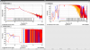
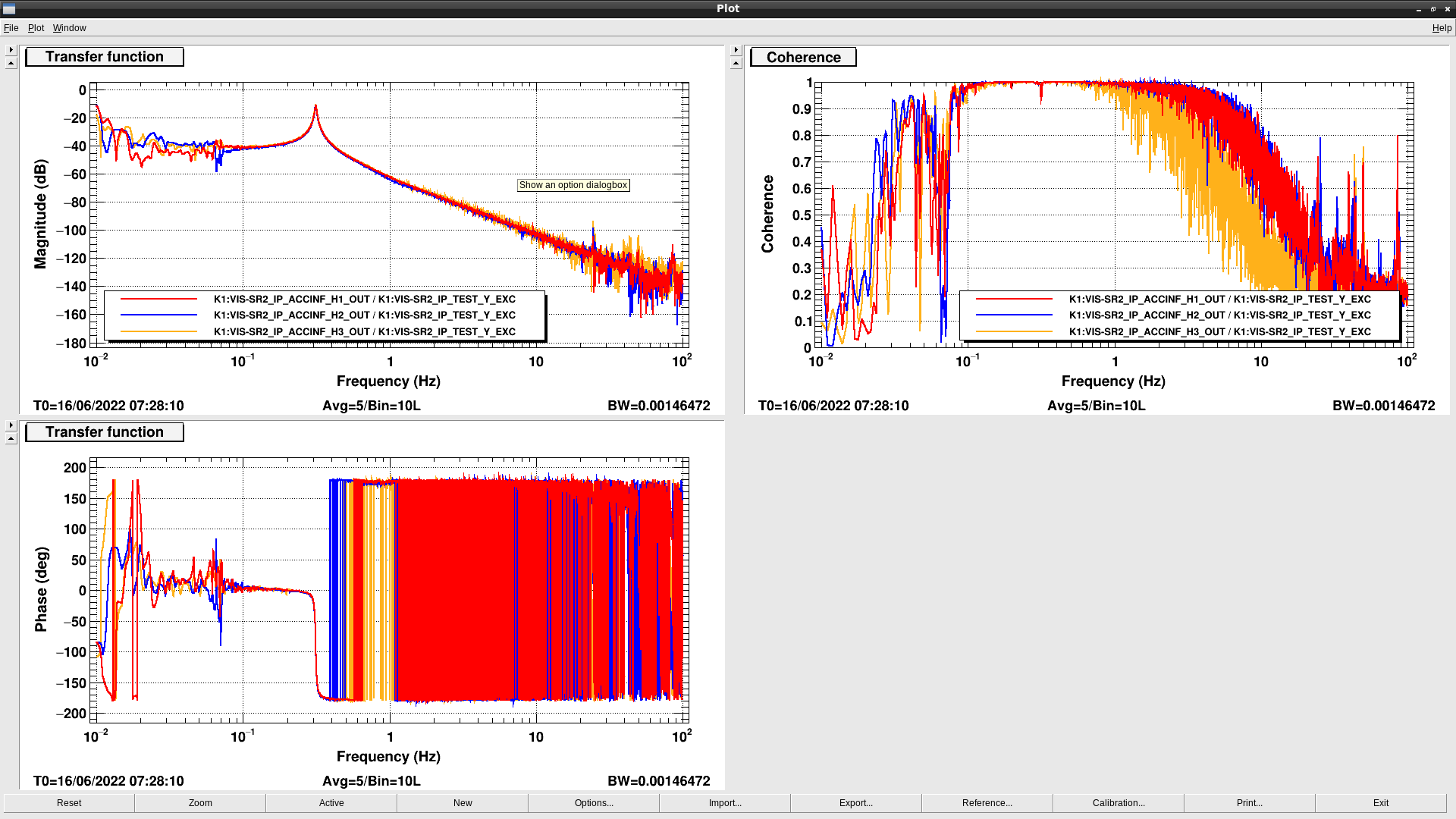
  1. I measured the TFs from yaw actuation to two different sets of outputs:
    • Set 1: raw output of the individual geophones, in units of cnt/cnt.
    • Set 2: displacement output of the individual geophones, using their calibration transfer functions that produce the bumps, in units of um/cnt.
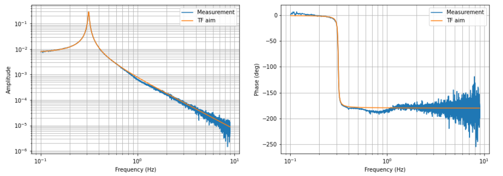
  2. I fitted each of these TFs in Set 2 with a mathematical model that does not allow the bump to appear, and fits well the resonance frequency and DC amplitude. For the fit, the values were weighed with a factor 1/f in order to favor lower frequencies where the resonance is.
  3. Then I defined a function containing the geophone parameters to determine (Ge , f0 and eta):  integrator(s) * m2um * ( 1 / H_geo ) * hp(s) * ( 1 / preamp ) * cnt2V * tf_raw
    • Integrator: conversion from velocity to displacement,
    • m2um: conversion from metres to micrometres.
    • H_geo( Ge, f0 , eta ) = Ge * s**2 / (omega0**2 + 2 * omega0 * eta * s + s**2 )
    • s = 1j *2 * pi * f
    • omega0 = 2 * pi * f0
    • hp: high-pass filter with four poles located at 3 mHz.
    • preamp = 940, this factor compensates the preamplifier gain.
    • cnt2V = 2 * 20 / 2**16, ADC conversion factor in units of V/cnt.
    • tf_raw: raw transfer function from Set 1.
  4. Then I fitted the function defined in step 3 to data generated with the function calculated in step 2.
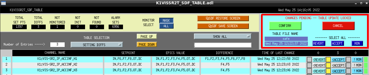
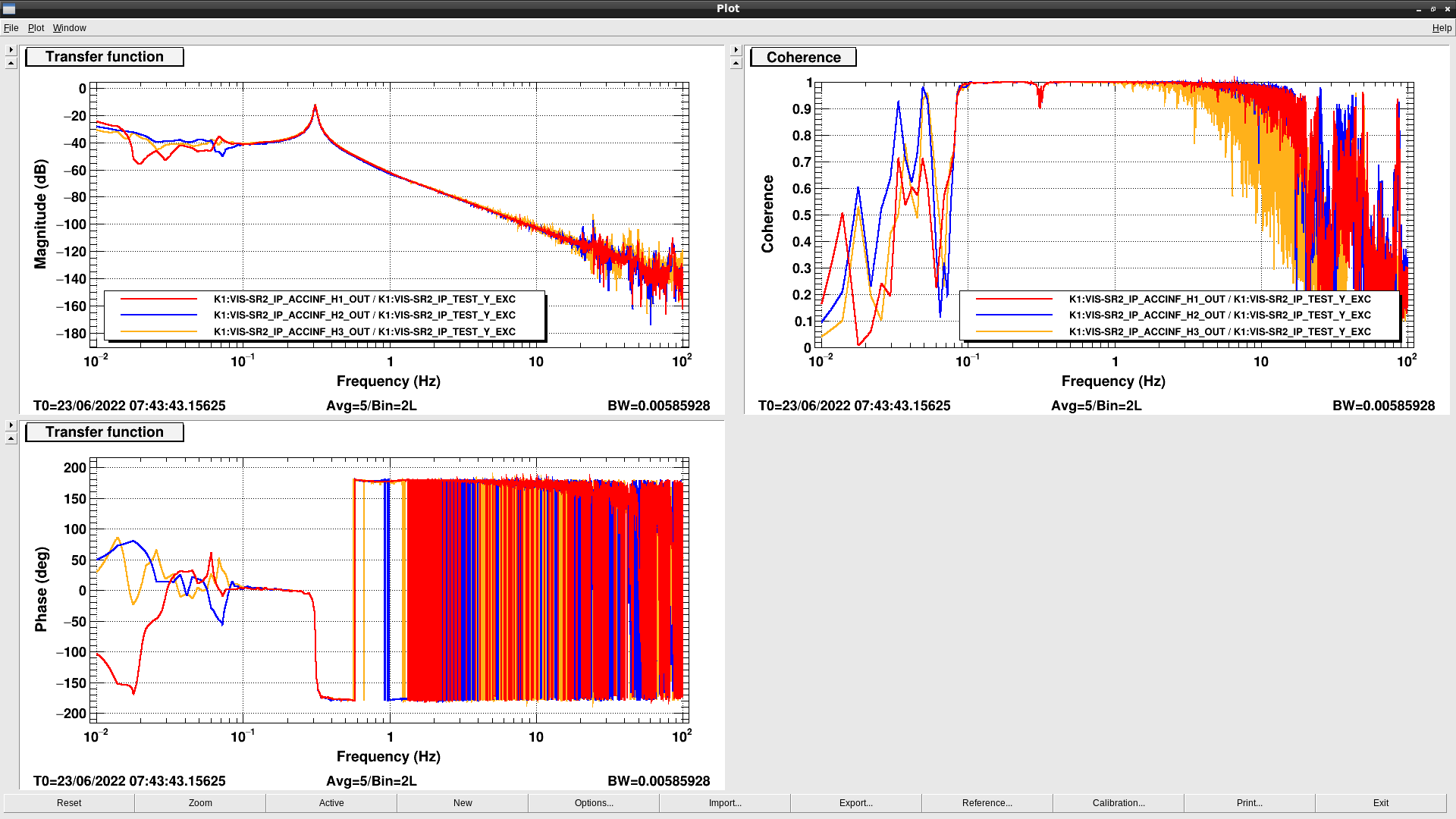
  5. With Foton, I put all these filters in the filter banks and measured again TFs.

In the table, the original values measured by Fujii-kun (entry 7059) and the new ones are shown.

Geophone name in SR2 Ge [V/(m/s)] f0 [Hz] Eta Ge [V/(m/s)] f0 [Hz] Eta
  Values from klog 7059 New values
Geo 4 (H1) 264.86 1.094 0.6022
265.114
1.079
0.2990
Geo 5 (H2) 267.535 1.193 0.5559
260.6117
1.125
0.2881
Geo 6 (H3) 269.65 1.401 0.4383
248.8686
1.204
0.2386

The observations are:

  • All the resonance frequencies f0 decreased, namely, by 15, 68 and 197 mHz for H1, H2 and H3 respectively.
  • The damping factors Eta decreased by factors of 0.49, 0.51, 0.54 for H1, H2 and H3 respectively.

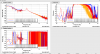
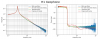
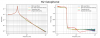
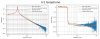
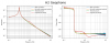
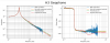
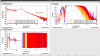
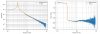
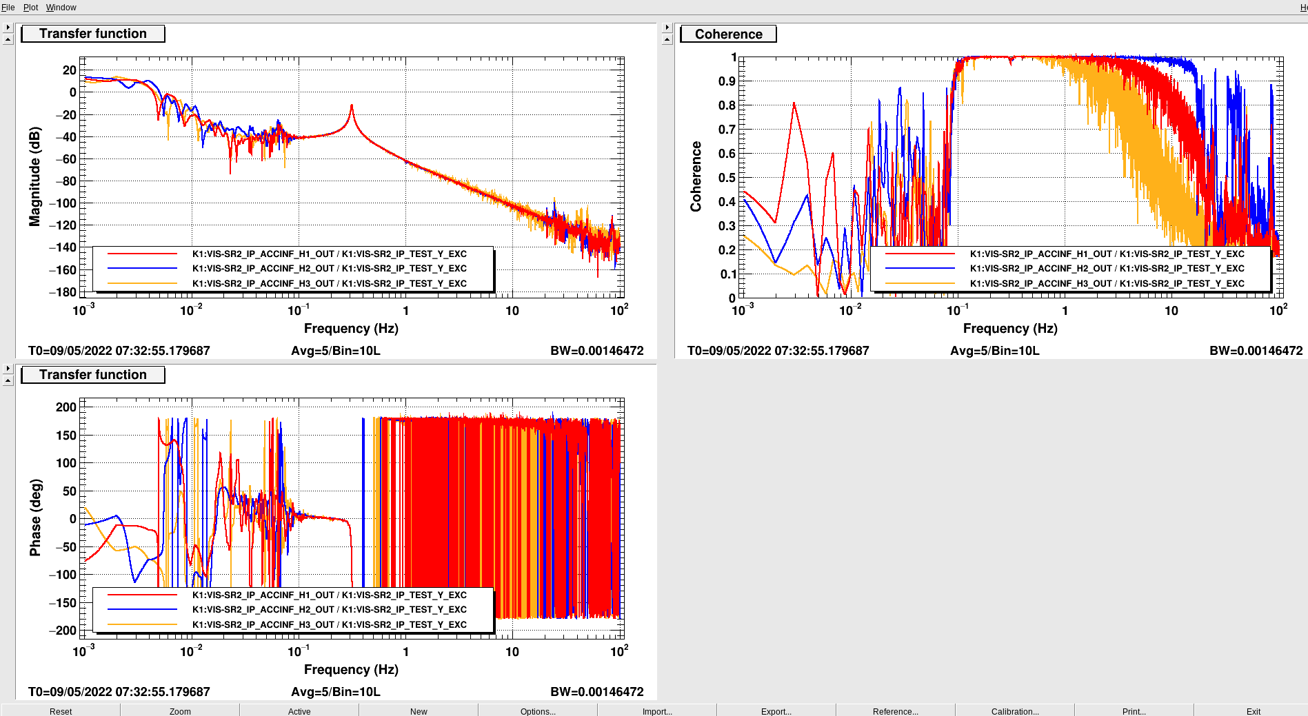
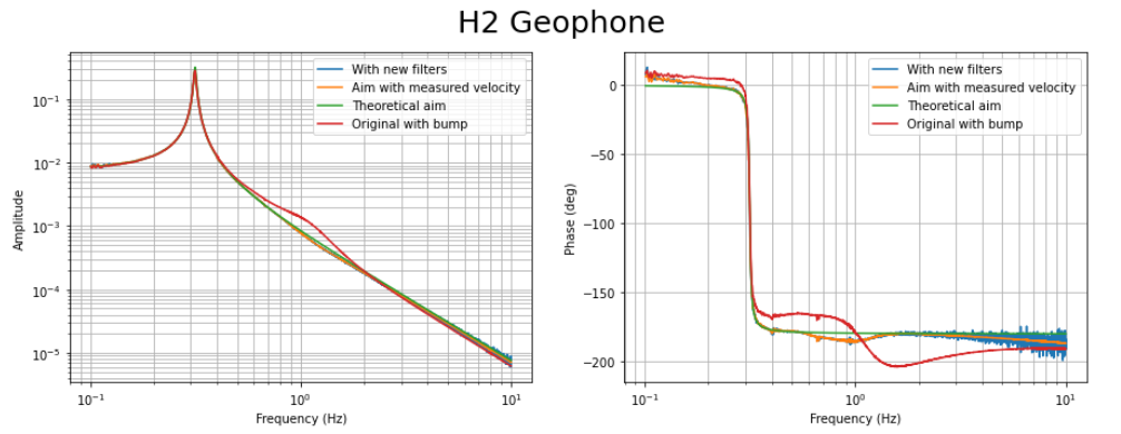
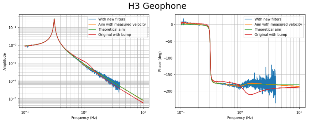
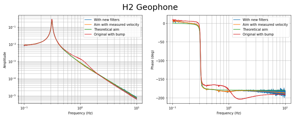
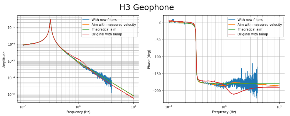
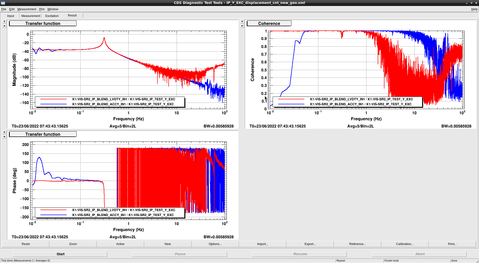
The plots show the following quantities:

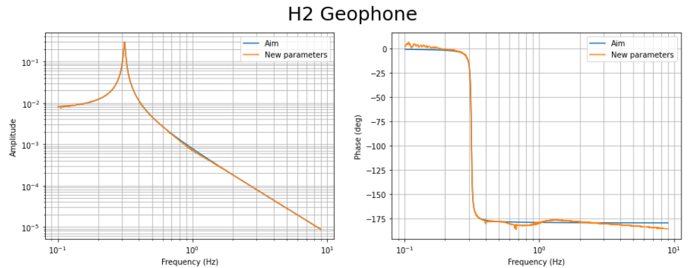
  • With new filters: TF measured with corrected geophone parameters (step 5 above).
  • Aimed with measured velocity: TF calculated with the measured raw TF (Set 1 in step 1) and the geophone calibration function with new parameters.
  • Theoretical aim: Transfer function calculated in step 2.
  • Original with bump: the name is explanatory.

From the plots, it's clear that the results are alright and, therefore, I'll continue with the following step, which is inter-calibration between geophones and LVDTs. However, it seems the results could still be improved.

Images attached to this comment
fabian.arellano - 14:16 Wednesday 25 May 2022 (20870) Print this report

I turned  on the filter banks with the information of the geophone calibration (klog 20808), and updated the SDF while the suspension was in SAFE mode.

Images attached to this comment
fabian.arellano - 17:37 Thursday 16 June 2022 (21155) Print this report

Summary: After we changed the geophone H2 (klog 21084), I double-checked its parameters values given in the datasheet by measuring the IP transfer function in yaw, including the raw input. I'll post the result of the analysis in another klog.

The new geophone is #37, with parameters

  • f0 = 1.03Hz,
  • Eta = 0.291, where Eta = 1 / ( 2Q ) with Q = 1.72,
  • Ge = 288.31 V/m/s

Then, in the filter bank for geophone H2, using the new parameters, I replaced the old filters with new ones

  • InvGeoGain = m2um * ( 1 / Ge ) * ( 1 / preamp )
  • InvGeo+Hp =  ( 1 / H_geo ) * hp

where

  • m2um: conversion from metres to micrometres.
  • H_geo( Ge, f0 , eta ) = Ge * s**2 / (omega0**2 + 2 * omega0 * eta * s + s**2 )
  • s = 1j *2 * pi * f
  • preamp = 940, this factor compensates the preamplifier gain.
  • hp: high-pass filter with four poles located at 3 mHz.

The file is in /kagra/Dropbox/Subsystems/VIS/vis_commissioning/sr2/inter_calibration/

Images attached to this comment
fabian.arellano - 12:42 Friday 17 June 2022 (21166) Print this report

Erratum for klog 21155:

It's written

H_geo( Ge, f0 , eta ) = Ge * s**2 / (omega0**2 + 2 * omega0 * eta * s + s**2 ),

but it should be

H_geo( Ge, f0 , eta ) = s**2 / (omega0**2 + 2 * omega0 * eta * s + s**2 )

without the Ge factor at the front.

fabian.arellano - 13:51 Friday 17 June 2022 (21168) Print this report

Summary: I noticed that the TF of  IP-Y with the new geophone, had a depression around 1 Hz, so I calculated corrections to the geophone parameters.

From the measurement of the IP yaw transfer function, it was possible to see that the H2 transfer function had a depression at around 1 Hz. Fig. 1 shows such a measurement and a model of how the graph should look like.

As I did before (klog 20808), I adjusted the parameters to try to correct this depression. The old and new values are

Old

  • f0 = 1.03Hz,
  • Eta = 0.291, where Eta = 1 / ( 2Q ) with Q = 1.72,
  • Ge = 288.31 V/m/s

New

  • f0 = 1.004 Hz,
  • Eta = 0.3134179,
  • Ge = 272.752 V/m/s

Fig. 2 shows the calculated TF using the new parameters and the aim. Although it's not completely straight yet, it's better and acceptable,

Images attached to this comment
fabian.arellano - 17:10 Thursday 23 June 2022 (21249) Print this report

Using the new geophone parameter values (klog 21168), I calculated the Foton expressions of the calibration filters for the new geophone used as H2, then I updated the filter bank. I measured the transfer function to make sure there was no mistake.

The file is in /kagra/Dropbox/Subsystems/VIS/vis_commissioning/sr2/inter_calibration/

Images attached to this comment
Search Help
×

Warning

×