Cont'd from 17135. Slack discussion in advance with Enomoto, Izumi, Michimura, Tanioka.
Abstract
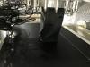
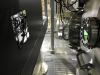
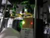
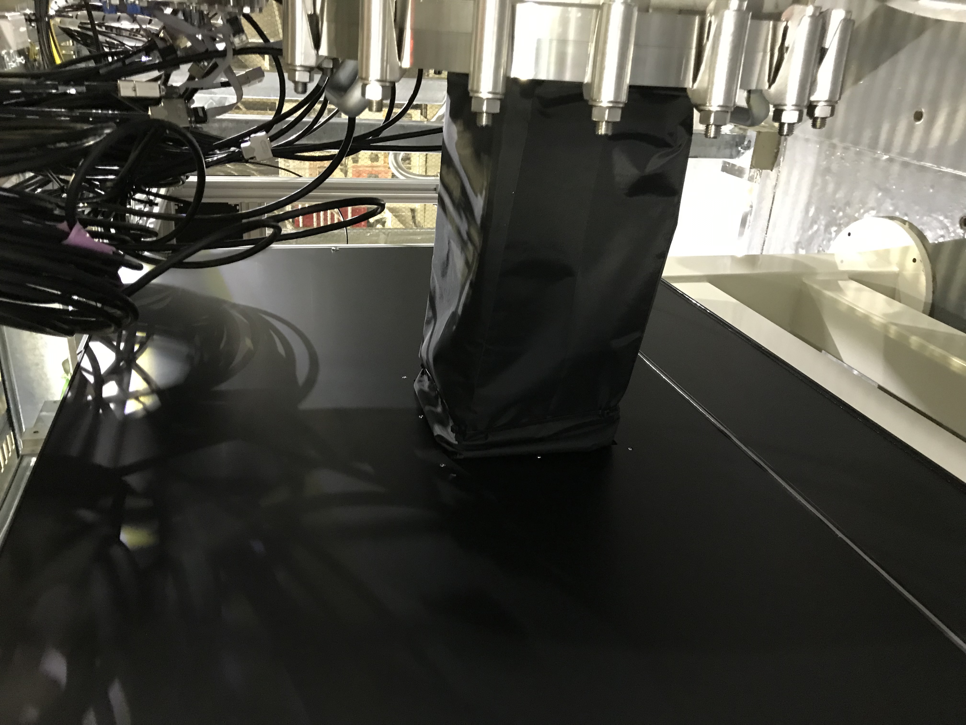
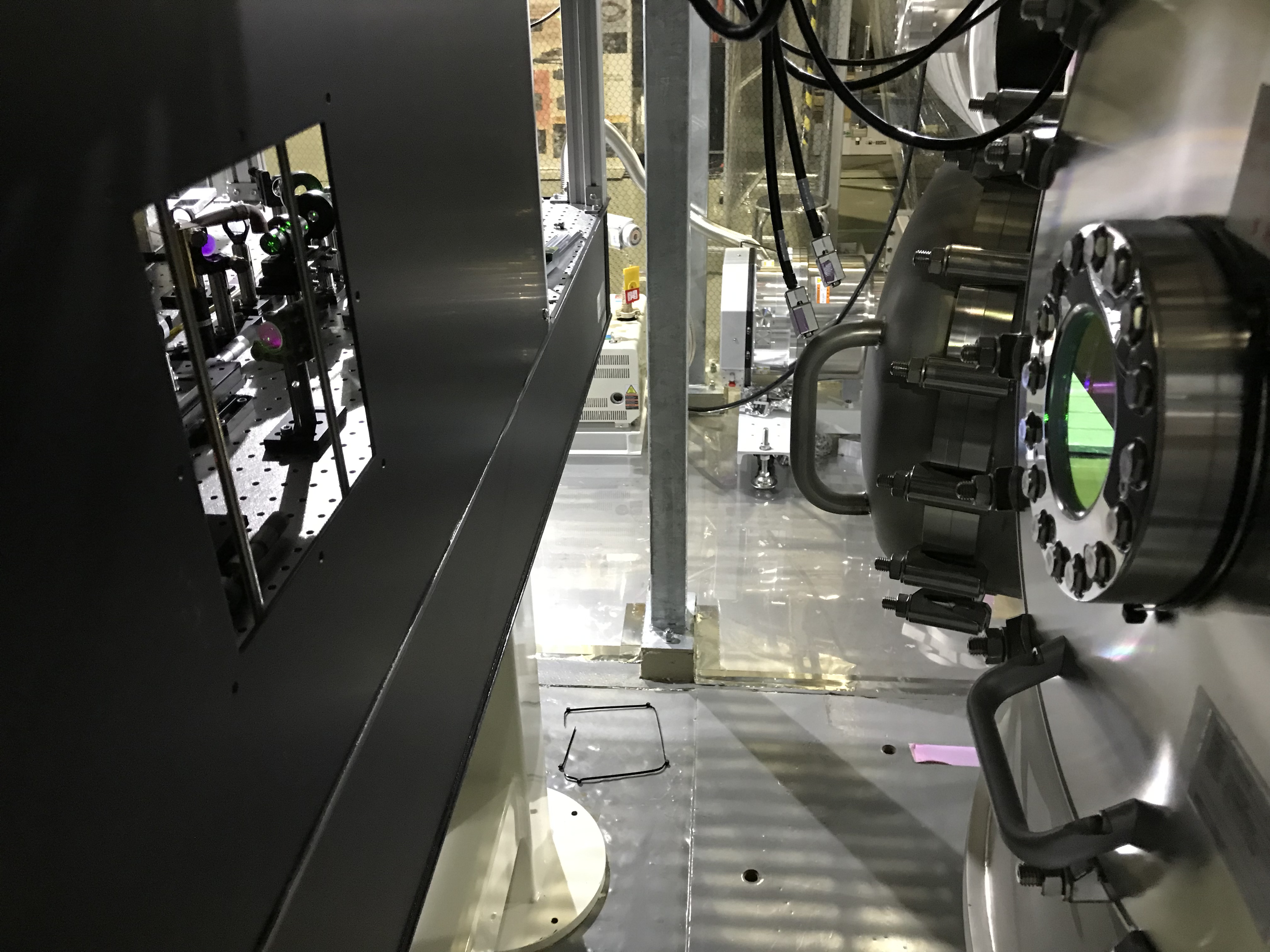
Detached a wall and a tube of the cover off the POP in-air table to have better accessibility to the workspace (Figs. 1 and 2). Investigated IR and green beam separations around POP and PR2.
Detaching the cover
Considering the situation, I needed to have better accessibility for the periscope on the POP table, so I detached another wall, and also the tube that connected the cover and the PR2 chamber. Now I can have a better view around the periscope, and can see where the IR beam from PR2 is, and where the green beam spots are. This was a tough work, and I do not want to do this again. Never...
Re-aligning the green beam
One needs a very carefulness about the mirror alignment around POP-PR2 (maybe so do POS-SR2). The pick-off mirror behind PR2, i.e. POP-POM needs to treat mainly three laser beams as follows.
- Input/extract the green beam for ALS-X (GrX or GreenX).
- Extract the IR beam from PRC (PR2_TRANS_BACKWARD). This is almost overlapping with GrX.
- Extract the IR beam from IMMT2 (PR2_TRANS_FORWARD). This will be important for the global input beam pointing, and to be established for O4 as one of lessens of O3GK.
As described above, 1 and 2 are overlapping, and 2 is not existing just now. So what I need to consider are 1 and 3. If one would tweak POP-POM, two things would happen; GrX spot on the PR3 HR target would move, and PR2_TRANS_FORWARD would also move; this is the origin of difficulty of this work.
According to my (+ Takeda-kun’s) ray-trace around POP-POM, the beam-spot separation on the POP-POM should be about 9.6 mm (i.e. 4.8 mm each side of the center), and the tilt angle of the POP-POM should be 47.8 deg. With this, on the viewport for PR2-POP, the distance between (-X edge, GrX spot), (GrX spot, PR2_Forward spot) (PR2_Forward spot, +X edge) are 26, 24, or 30 mm respectively... (hopefully I will make a slide)
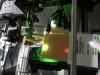
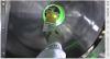
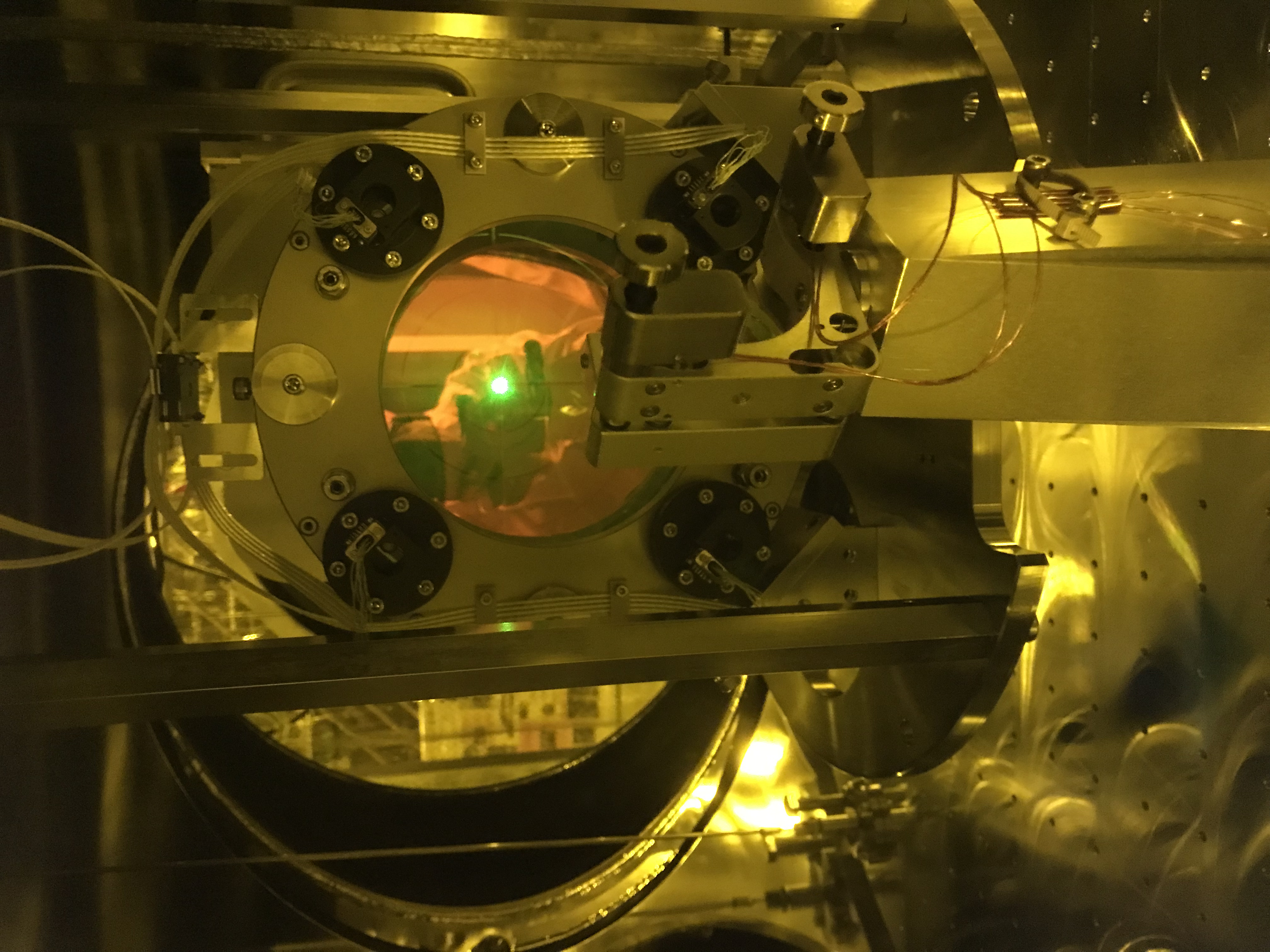
Let us assume that the rough alignment of POP-POM had been done before O3GK, and would be still effective. If this is the case, for example, by tweaking some mirrors on the POP table, I can expect GrX will go very close to the centers of both PR2 and PR3, without touching POP-POM. So, by looking at the target plate placed at PR2 HR from behind, I tweaked HBS in yaw, and lower periscope mirror in pitch, until GrX came to illuminate the PR2 HR target center (Fig. 3). The HBS yaw seemed the best sensitive amoung the three mirrors (HBS, upper periscope mirror, and lower periscope mirror). For pitch, I am not sure myself well why I choose the lower periscope mirror, but anyway, these were done. As a result, immediately after detaching the PR2 HR target, I found the GrX spot on the target plate at PR3 HR. Good!
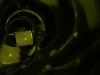
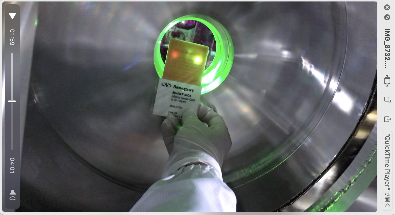
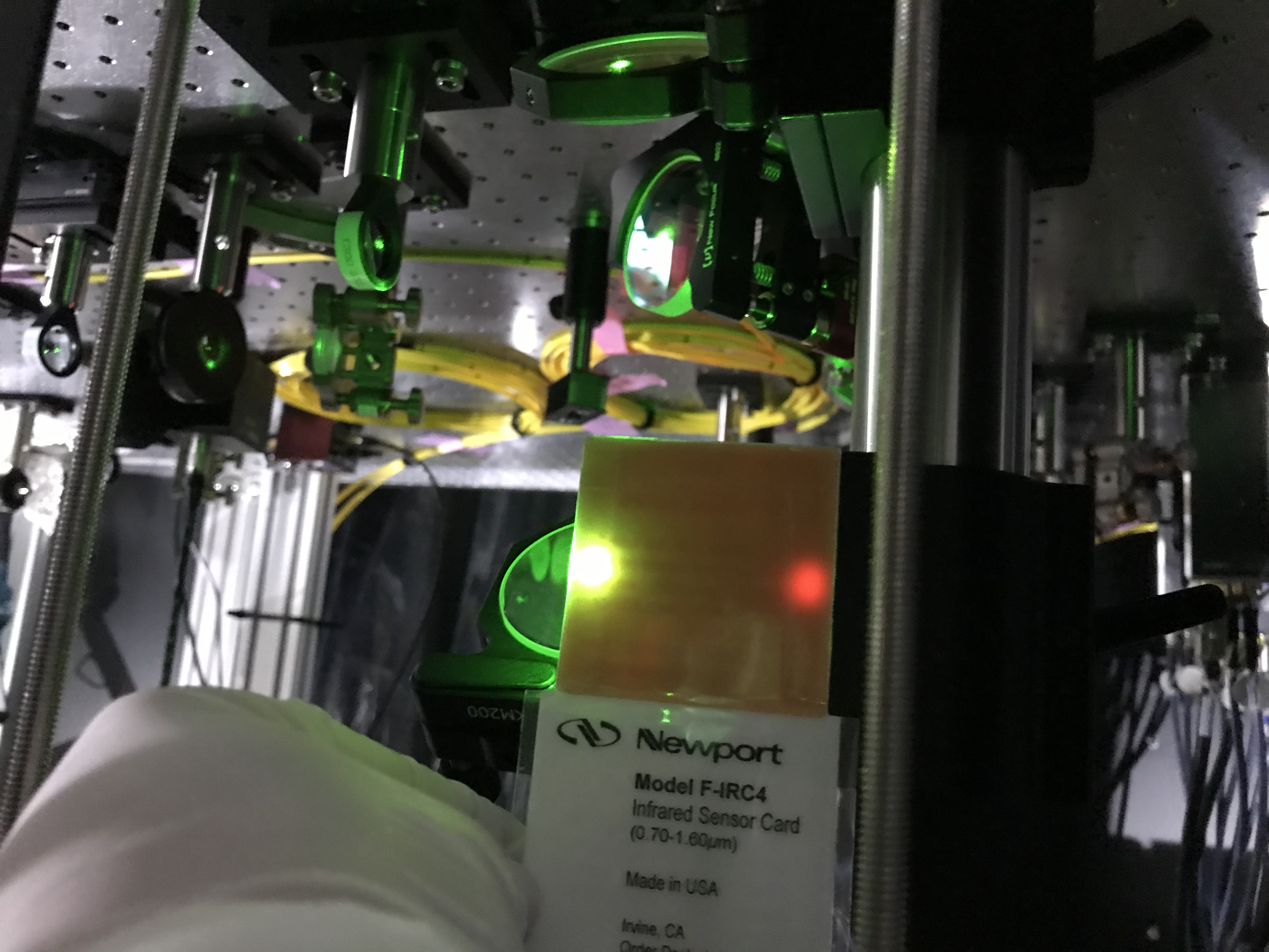
On the other hand, I also checked the GrX spot on POP-POM; it seemed close to the "designed" position. As the green power was so strong, it was hard to check better. I'd like to do this check when reducing the GrX power by a HWP in front of the Faraday on the POP table (maybe). Due to detaching the PR2 target, PR2_TRANS_FORWARD also appeared on POP-POM. This IR beam was reflected there, and went out of the PR2 chamber, and illuminated the pillar of the periscope (although this was anticipated... unlucky). The beam separation of GrX and IR was, at this time, larger than the design (Fig. 4; depeding on which strategy we will go, this situation would not so bad, as they are well separated while they are not clipped at the viewport).
Anyway, expecting my luck and the assumption described above would stand, I tweaked POP-POM so that GrX spot would come close to the center of PR3 HR target, and looked at the behavior of the PR2_TRANS_FORWARD spot. Today I worked alone for some reason, it was difficult to see the PR3 target about 15 m away, but somehow I made it closely (Fig. 5; actually this photo was taken with PR2 target. The masked beam pattern can be seen.). Moreover, as expected, the PR2_TRANS_FORWARD beam path seemed to come closer on the designed line (Figs. 6 and 7), maybe; need a further check later. Seems still larger separation than that of the design. Maybe due to that the GrX spot on PR3 target is still off centered.
Next step
- Move (mirro-symmetric) the periscope: it seems we cannot avoid PR2_TRANS_FORWARD hit the periscope pillar. Firstly, we wished the two beams could be taken with these three 2-inch mirrors, but some of us feel both the design and estimation say that would be too optimistic (in short, impossible in the real world). So we need to move the pillar of the periscope for GrX while keeping the GrX line, and so we can put another pillar for IR. To do these works, we must detach another wall off the cover of the POP table. Wow! When moving the periscope, maybe I will put some iris diaphrams to preserve the optical axis.
- Prepare the POP-POM picomotor driver: by hand tweaking the POP-POM picomotors, I could not avoid shaking the suspended breadboard in the PR2 chamber... Seemed Q~20 or so! A time loss.
- Reducing the green power: as described above, maybe better to reduce the green power on the POP table to avoid saturation.
