Nakano, Yokozawa, Akutsu
Abstract
We want to inspect whether the center points of PR2, PRM, and IMMT2 are now aligned or not. As a result, IMMT2 must be relocated in the direction of " -Y" by 1-2 cm from the current position, when we start the initial alignment of the interferometer for O4 in the (near) future. The relocation distance will be estimated soon later.
Details
The motivation of today's activity is stronogly related to 15602, and directly related to the initial alignment procedure of the interferometer. Because we cannot move PR2 and PRM so much due to mechanical limits, the optical axis between these two mirrors are almost determined within the machining/assembling errors. Under this constraint, IMMT2 must be on the same optical axis of this PR2-PRM line, but honestly speaking we did not know whether IMMT2 was located to satisfy this requirement during the initial optical alignment for O3. Especially, IMMT2 horizontal position is our main concern, as we have already learned that IMMT2 has been located at a different position by about 25 mm in +Y direction from that of in the "original" drawing. The beam dumps around IFI and IMMT2 are now designed, and so if the IMMT2 postion must be relocated later, we need to do re-design of the beam dumps, and that would be a waste of time (and money). So we want to know where IMMT2 was at the proper postion from the viewpoint of optical axis now.
With the KOACH setup shown in 15767, we opened alminum foils that closed the flanges at IFI, IMM, PRM, PR3, and PR2 chambers, and a vacuum tube between PR2 and PR3.
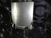
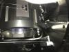
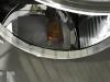
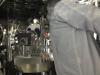
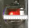
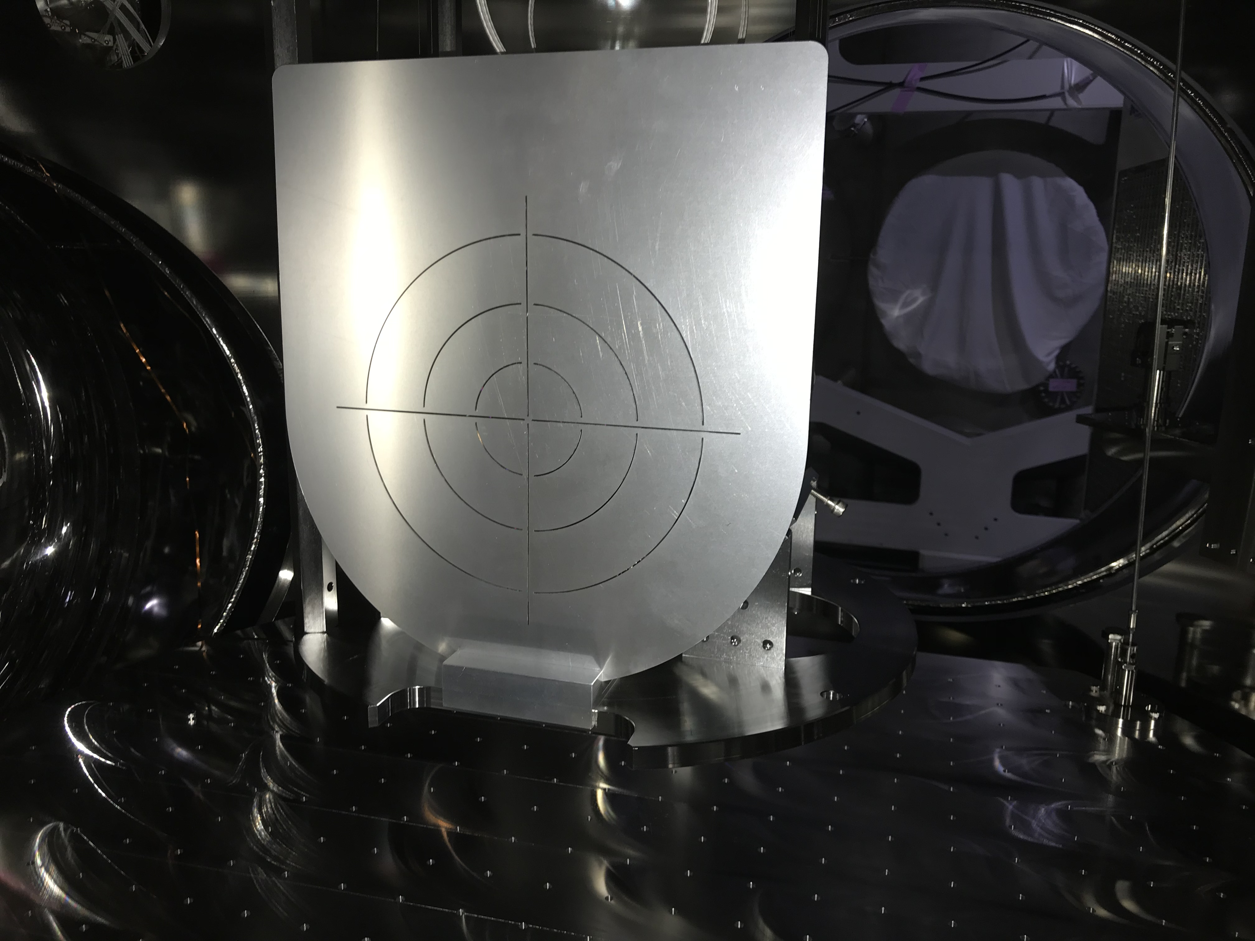
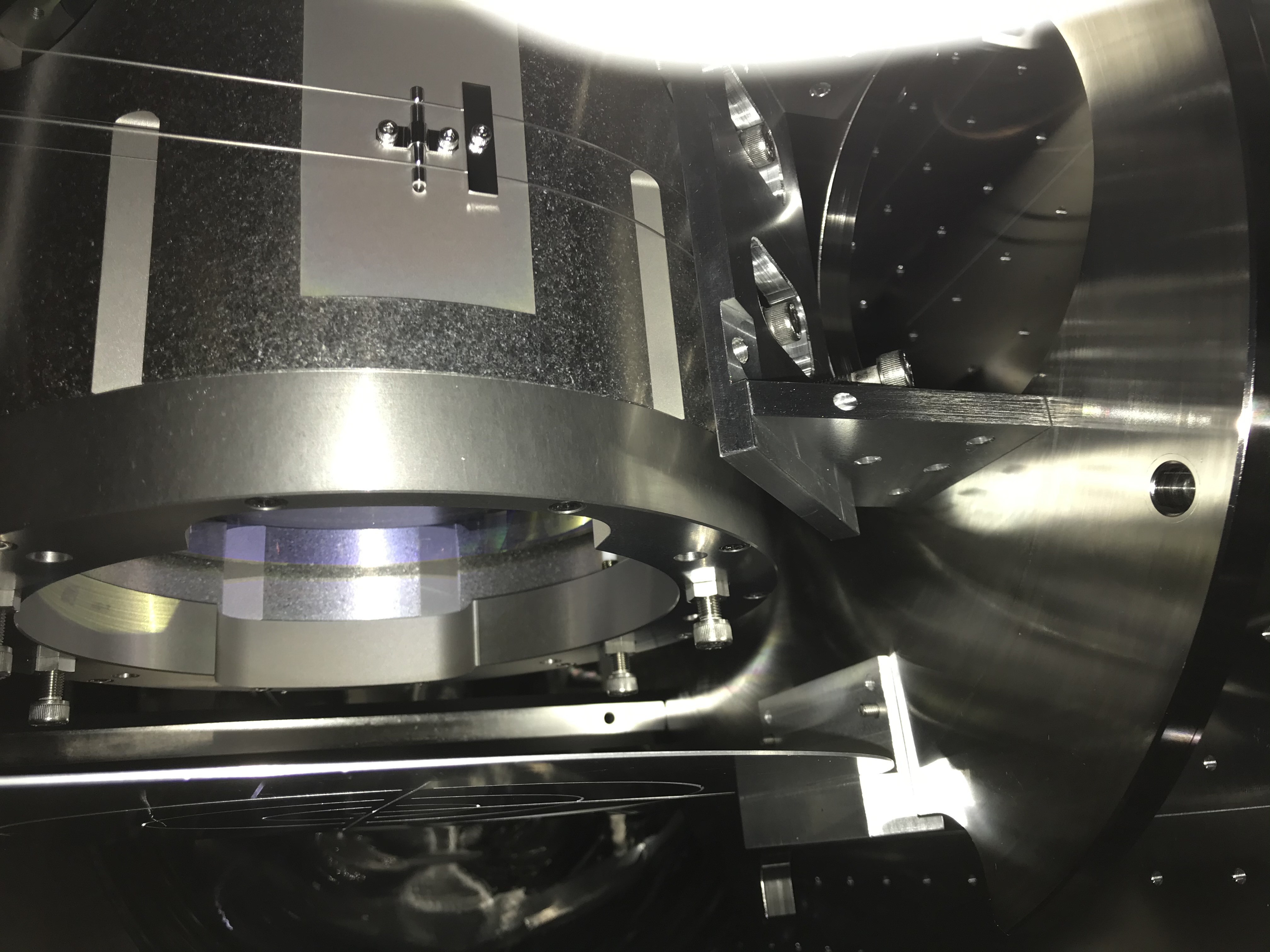
First, at PR2, we attached the beam target in front of the PR2 HR side (see also 5994) (Figs. 1 and 2). Then we found the beam spot was centered in yaw, and slightly lowered in pitch (~1 cm?) (Fig. 3; but slightly shifted in -Y?). As already mentioned, the error of the pitch position of the beam can be adjusted without relocating IMMT2, so this was not a big issue.
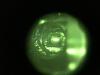
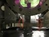
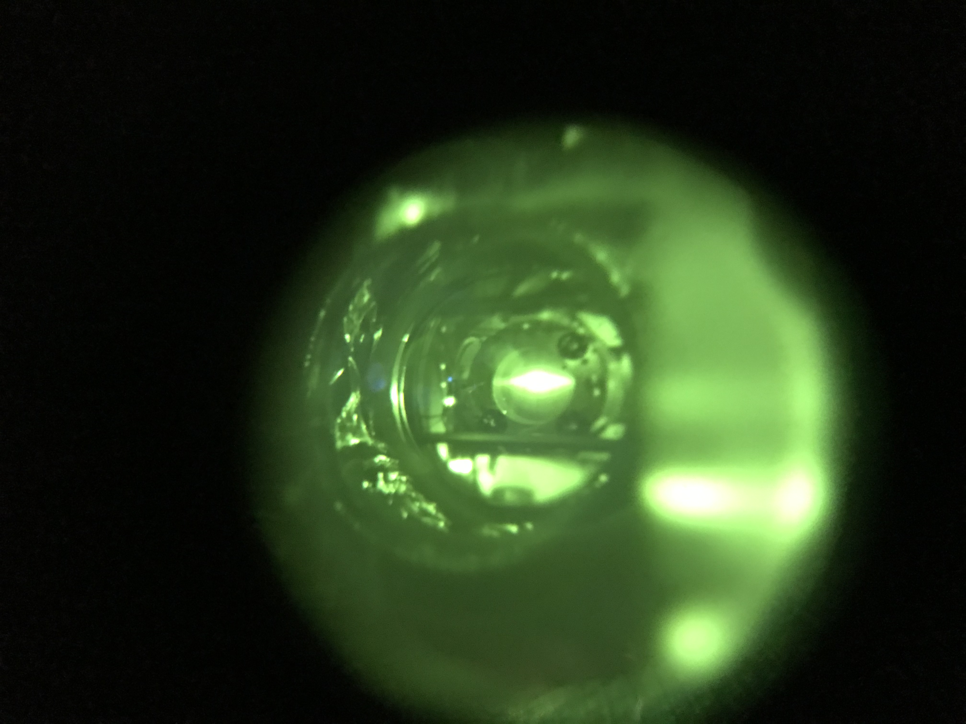
Next, at PRM, we attached the beam target at PRM HR side. As the laser beam was hitting from the back of the target, it was impossible to learn whether the laser beam was going through the center of PRM. Instead, we saw the beam position from the flange opening of the IMM chamber (note that the flange apertures between PRM and IMM is K400 and so small, and it was hard to make our bodies enter in-between the flanges) with the beam viewer. It seemed the beam spot was at the center of the PRM (Figs. 4 and 5; but slightly shifted in -Y?).
The beam spots on the PR2 and PRM would suggest that we can use the IR light beam itself as a reference line of our "ideal" optical axis, on which IMMT2 must be on. Note that IMMT1 position or alignment is not matter for this procedure, neither so the beam axis from IMC to IMMT1. Again, please recall that the "ideal" beam axis is determined by PR2 and PRM, so IMMT2 must follow this optical axis, and we need to align the light beam to be on this ideal axis by adjusting IMMT1 (and IMMT2).
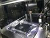
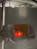
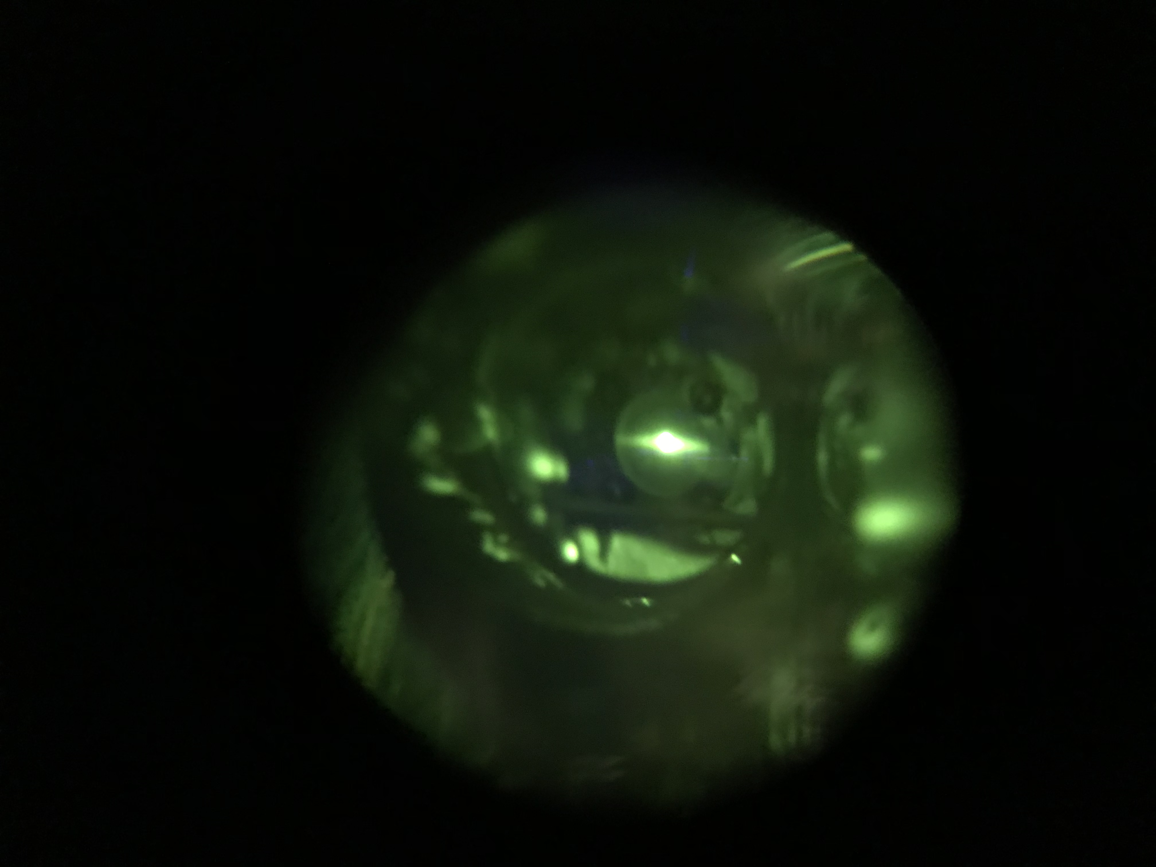
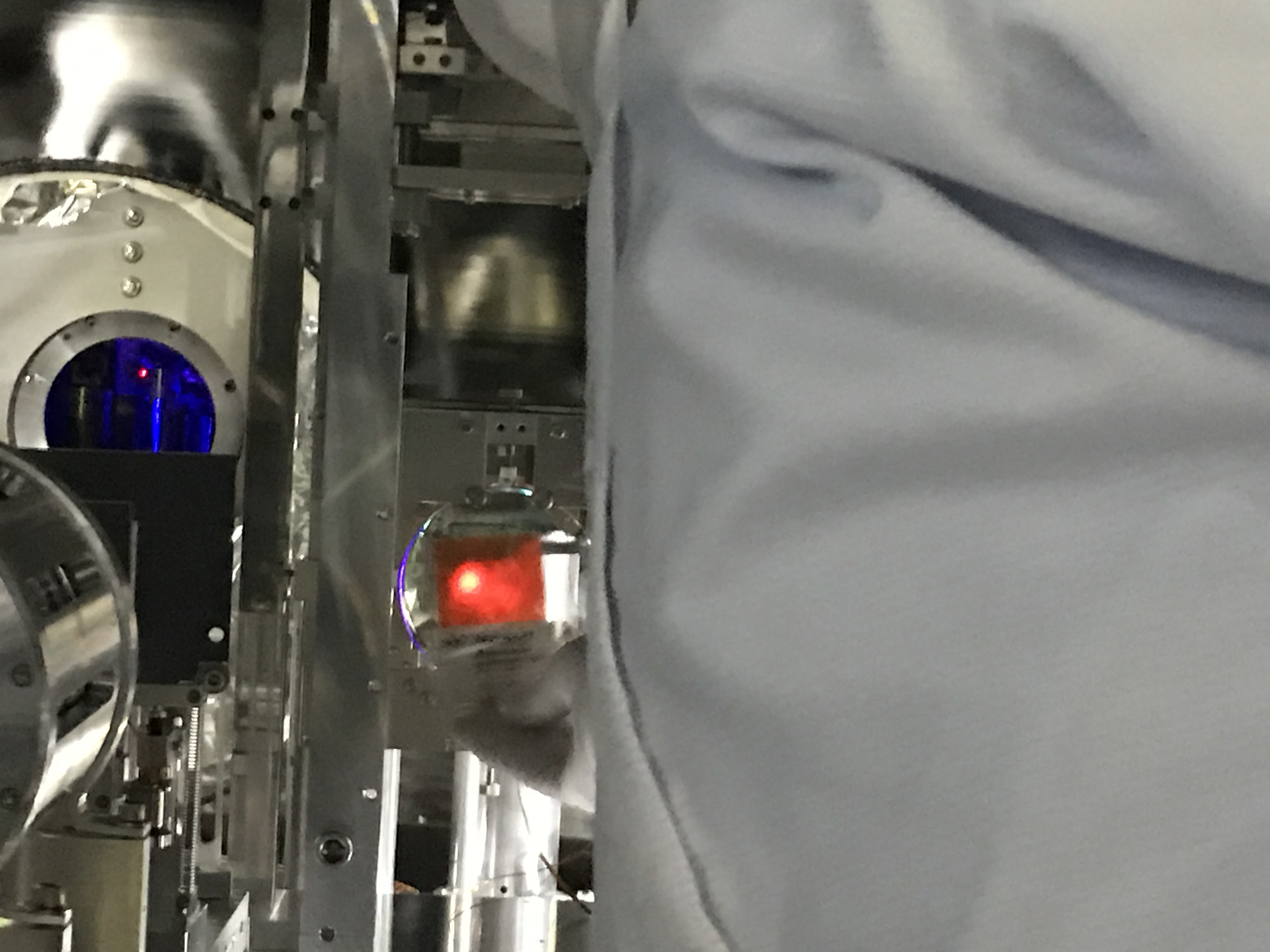
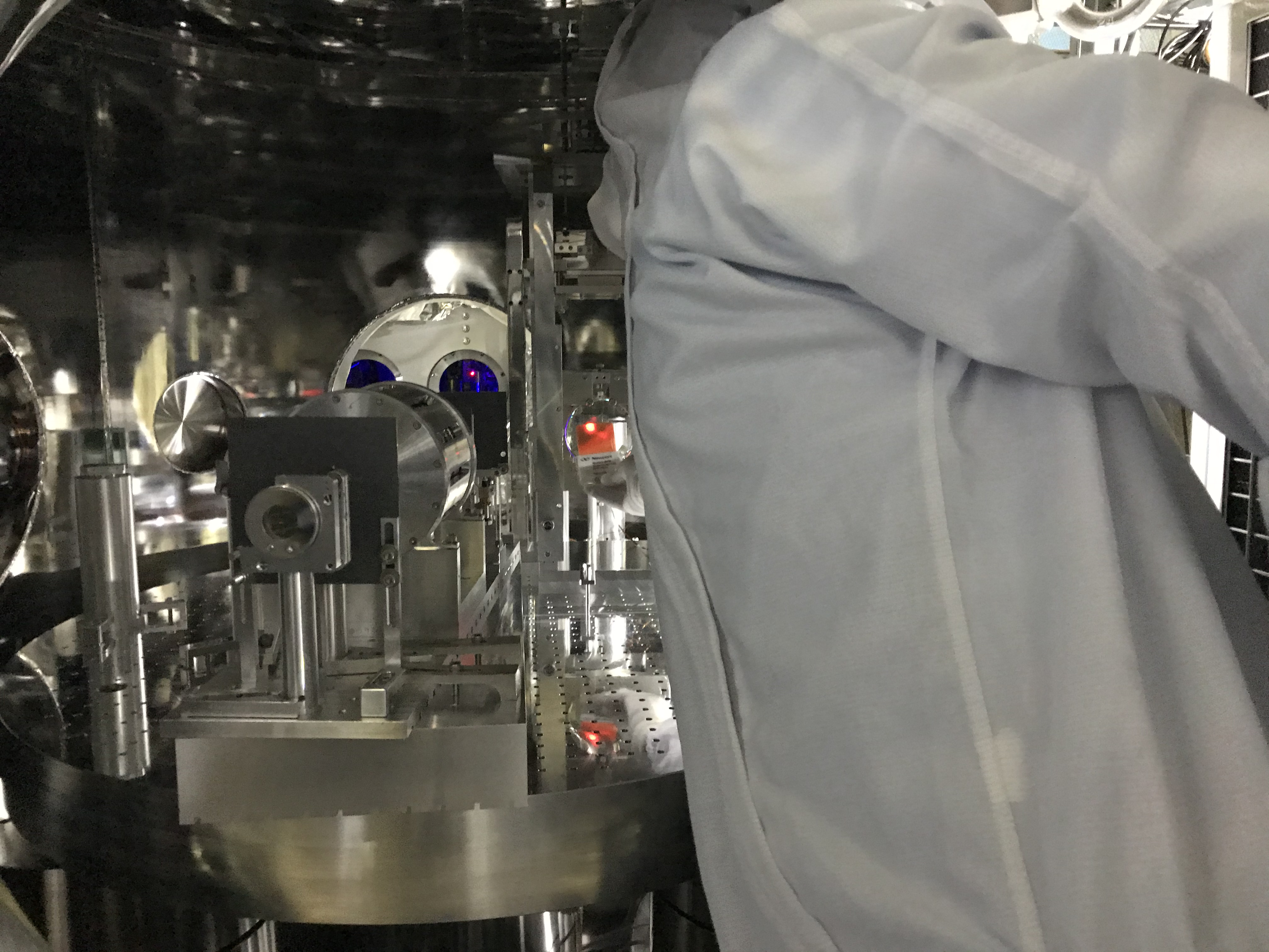
Anyway, at IMMT2, we saw the beam spot was displaced from the center of the IMMT2 mirror in -Y direction (Figs. 6 and 7 for front views, and Fig. 8 for a side view; we need to confirm the sensor card was actually as much close to the IMMT2 HR surface as possible to reduce parallax). This means we need to move the IMMT2 structure toward -Y direction. We can estimate the amount of the move from the photos. The beam dumps will be designed by assuming the IMMT2 structure will be relocated accordingly. And we should move the IMMT2 accordingly when we start the initial optical alignment for O4 later.
Notes
- There should have been two sets of the beam target, but we only find the single setup. There was another target plate but we could not find the adapter part for it. We need to find or buy it.
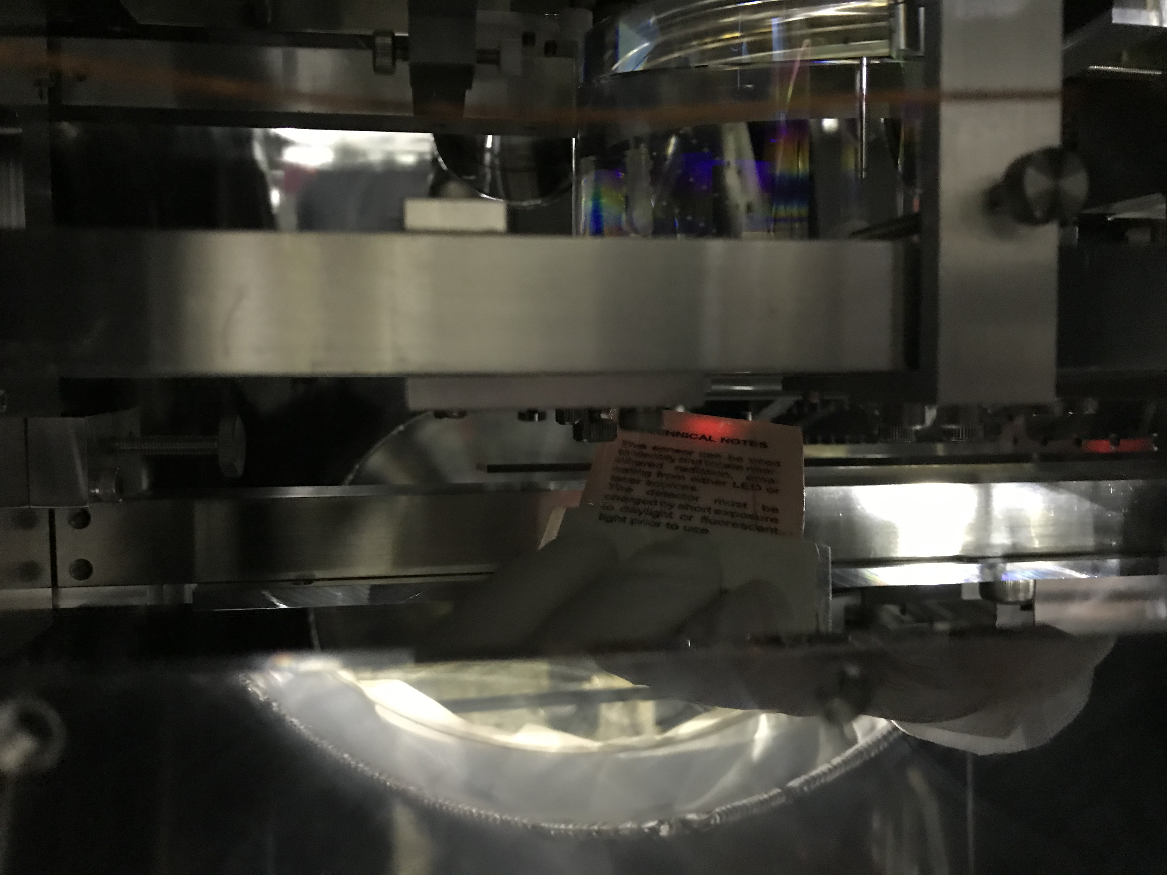
- The usage of the beam target was slightly varied (compromised?) from what Shoda-san had originally designed due to the actual situation in the chamber. Since the last time (first days for O3 comissioning such as 5994), the usage has been as follows: one fixes M5-25 screws from the bottom of the security frame for each mirror, and puts (but not fixes) the beam target assembly on the security frame with using the screws like support rods to hold it up (Figs. 9 and 10). Maybe the design needs to be revised.
- At IMM2, we detached the black shield plate to inspect whether the beam spot position on the IMMT2 mirror. The black shield plate is still (tentatively) being detached, and store on the optical table of IMC_REFL. Be careful not to touch the black surface, especially the edge of the center hole for optical axis!!! (see Fig. 11)
- Moreover, two mirror assemblies (a mirror, a mirror mount with two picomotors, a pillar, and a folk to fix the pillar) that will not be used anymore in the IFI chamber (maybe) were taken out of the chamber and tentatively fixed on the optical table for IMC_REFL as well (found in Fig 11 as well).


